


Story
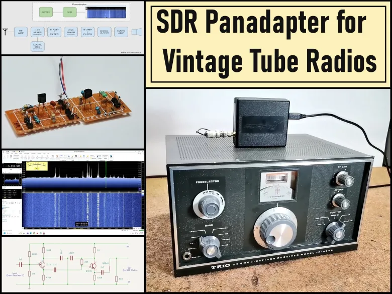
A radio panadapter (or panoramic adapter) is a device or software tool used in amateur radio and other radio communications to display a wideband spectrum view of signals around a selected frequency. It allows operators to visually monitor a range of frequencies in real time, rather than just listening to a single frequency. Panadapter shows a graphical representation of signal strength across a range of frequencies and helps identify active signals, interference, or unused frequencies.
Detailed video description at: https://youtu.be/XQkSS1b5phQ
There are generally two types of Panadapters :
- Hardware-Based: Dedicated external devices that connect to a radio's IF output.
- and Software-Based Panadapters that use SDR receivers (like RTL-SDR, SDRplay, or KiwiSDR) to display spectrum data on a computer.
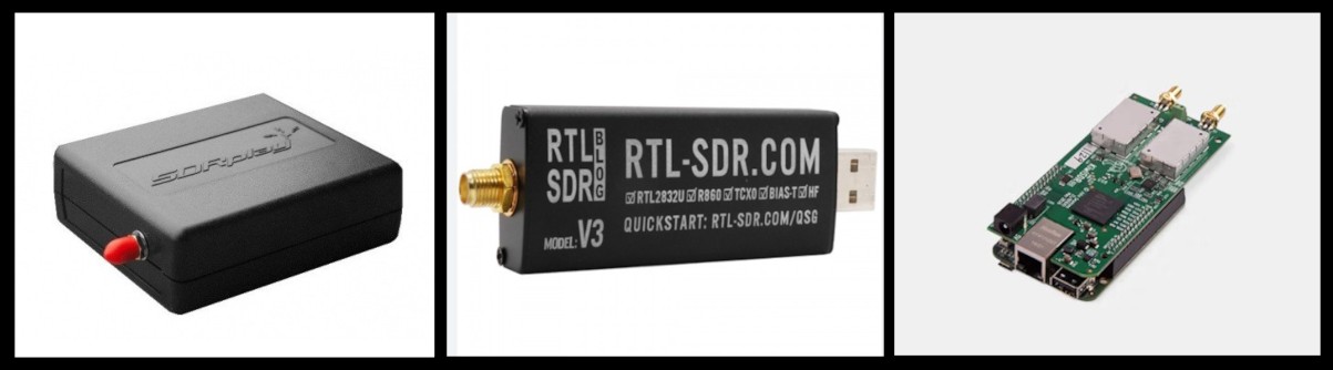
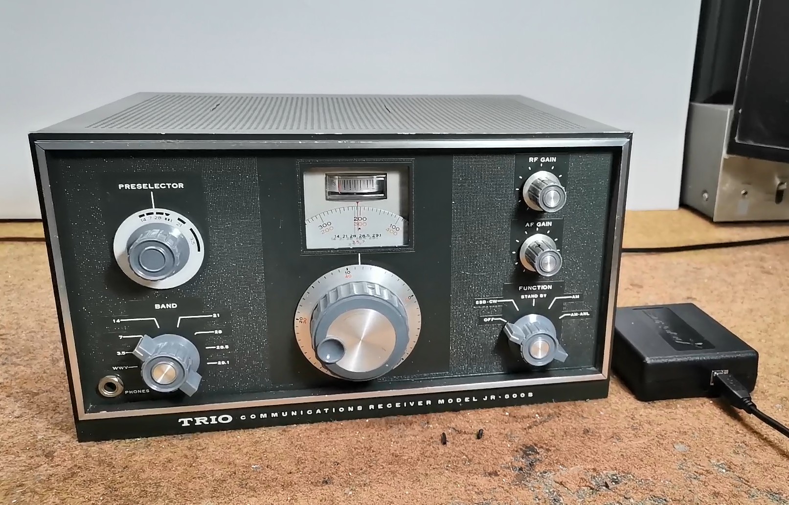
Specifically, in this project, I developed software based Panadapter, using my SDRPlay SDR radio receiver, but as I mentioned earlier, another type of SDR radio can also be used, such as an cheap RTLSDR dongle with appropriate software. This time I decided to modernize my old vacuum tube HF receiver model Trio JR 500S.
An excellent explanation of how to install and how the Panadapter works can be found on Scott Baker's website , from where I took the input part of the buffer and some pictures.
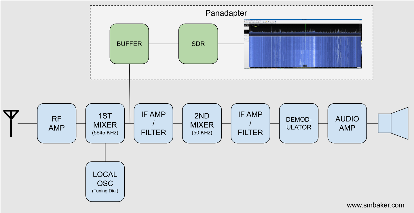
Most old tube and transistor receivers are of the super heterodyne type. The incoming RF signal mixes with a desired frequency from a local oscillator, to center that frequency around an intermediate frequency (IF). In our case, this IF is 8.9 - 9.5 MHz. So we should place the buffer amplifier immediately after the first mixer as shown in the diagram below.
The SDR receiver needs to be able to handle the intermediate frequency from your radio. My Trio JR500S has a 9 MHz intermediate frequency, but your radio may differ. It’s important to notice that the frequency on your SDR receiver will be centered around the IF, in my case 9MHz, wich is no problem for my SDRPlay. Regarding the connection point of the panadapter, this is the schematic of my radio, and the board should be connected immediately after the first IF transformer, i.e. at the point marked with the yellow arrow.
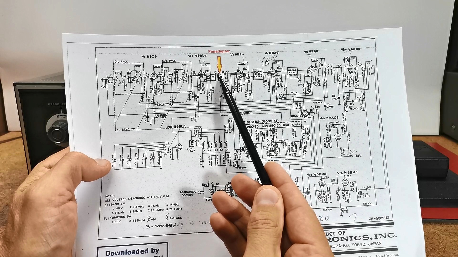
The board should be mounted as close as possible to this point so that there is no additional interference due to the length of the cable. In almost all superheterodyne receivers the panadapter should be connected immediately after the first IF transformer.
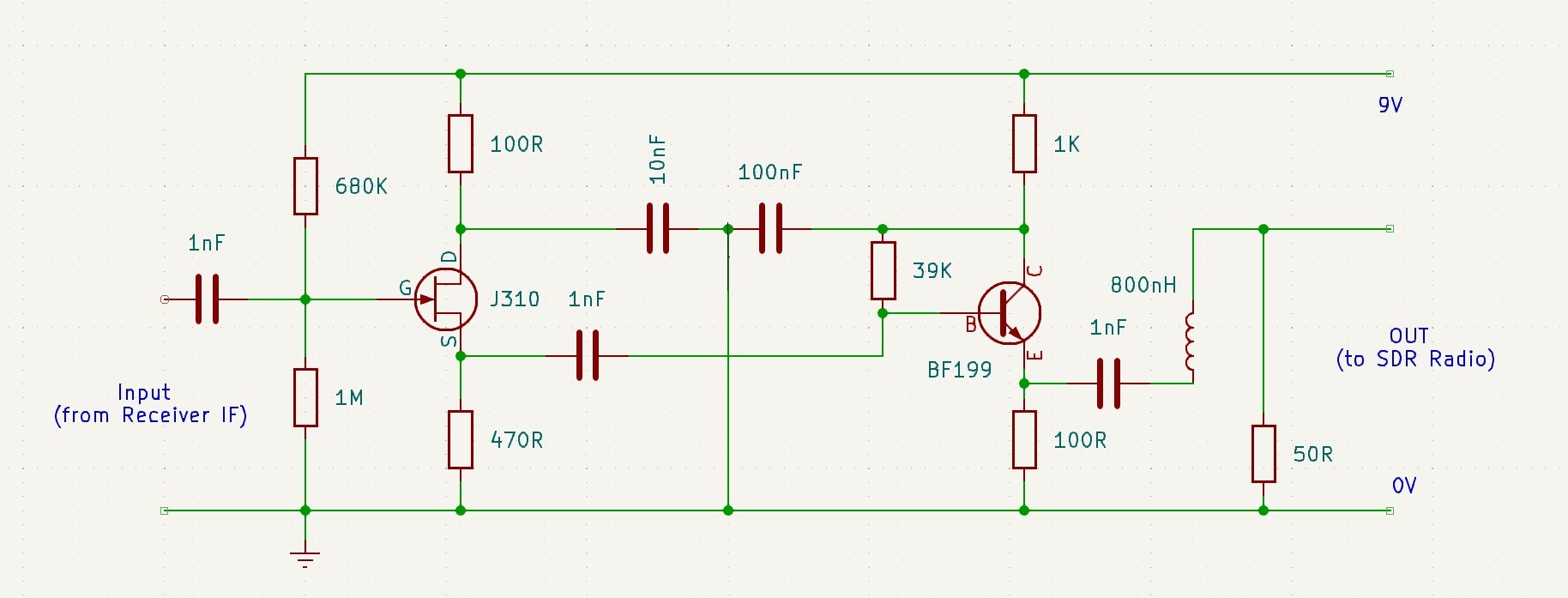
And now a few words about the buffer board. Tube radios are often very high impedance signals. They’re meant to drive loads into the hundreds of kiloohms or even into the megaohms. If you take a regular amplifier designed for a 50 Ohm input impedance, you’ll suck the signal right out of your radio and there will be nothing. You’ll completely load down the receiver. Therefore, the buffer amplifier shown in the diagram below has a very high input impedance, and a low output impedance, so it does not affect the received signal at all. The buffer has two active stages - a JFET source follower to present a high impedance to the IF filter, and therefore minimise any loading on the main signal path of the radio.
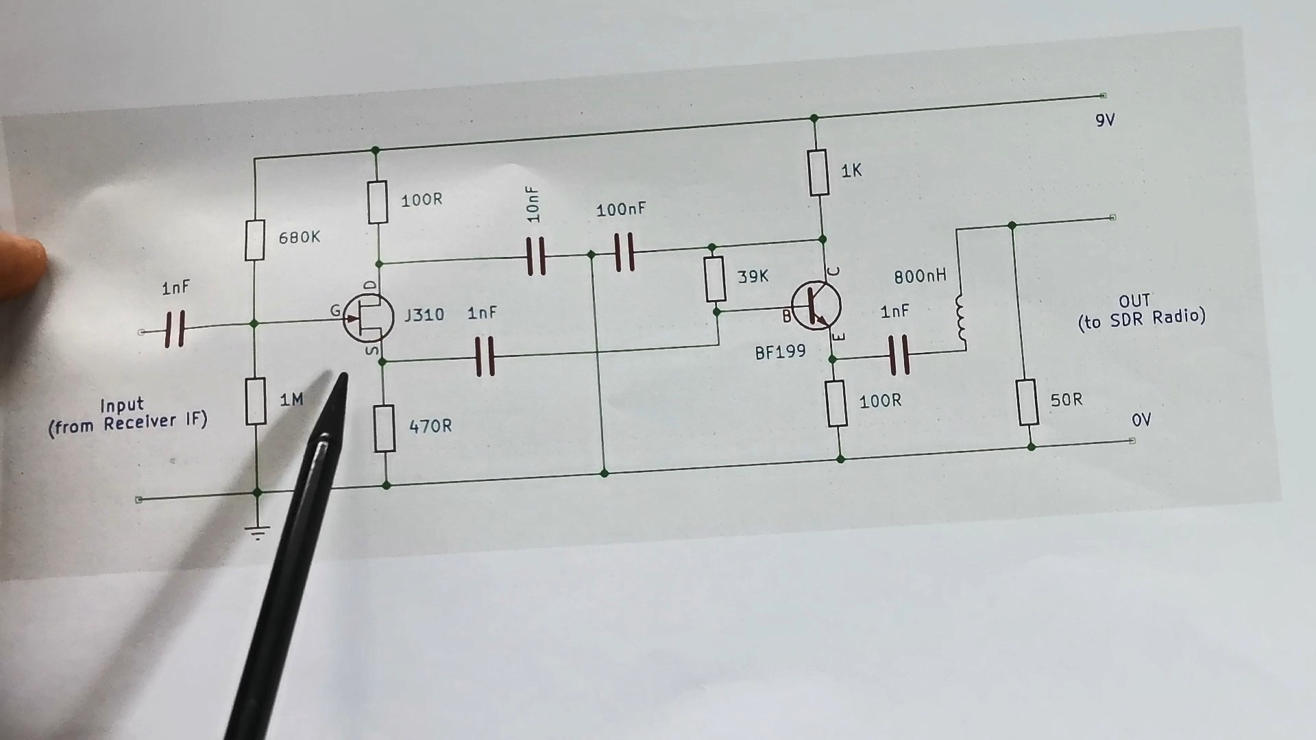
Then followsa BJT Transistor as an emitter follower to provide impedance transformation for a following filter stage. And finally, I added a very simple 10MHz / 3dB Lowpass filter consisting of a single inductor and a resistor.
Here's what the PCB looks like mounted in the radio.
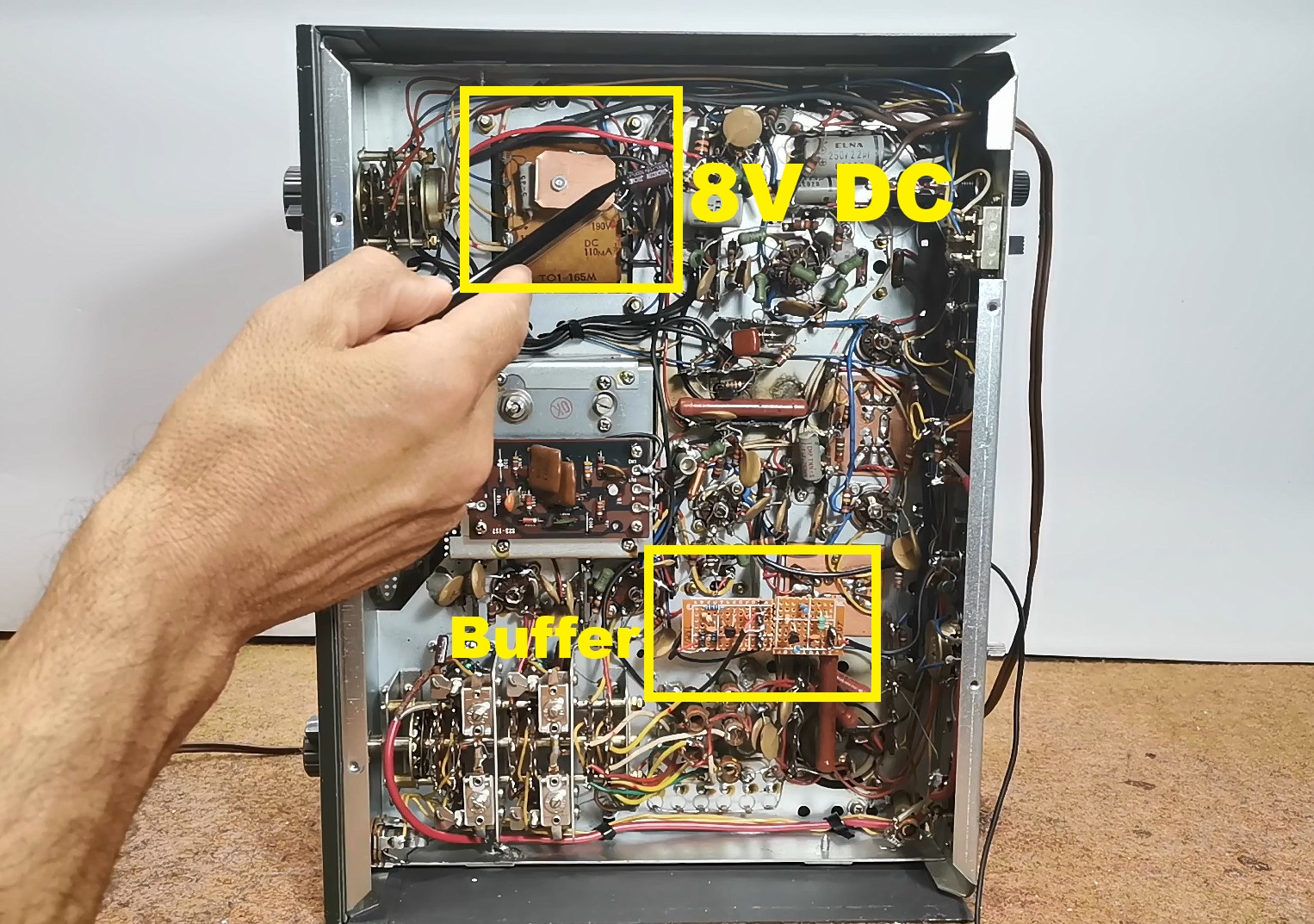
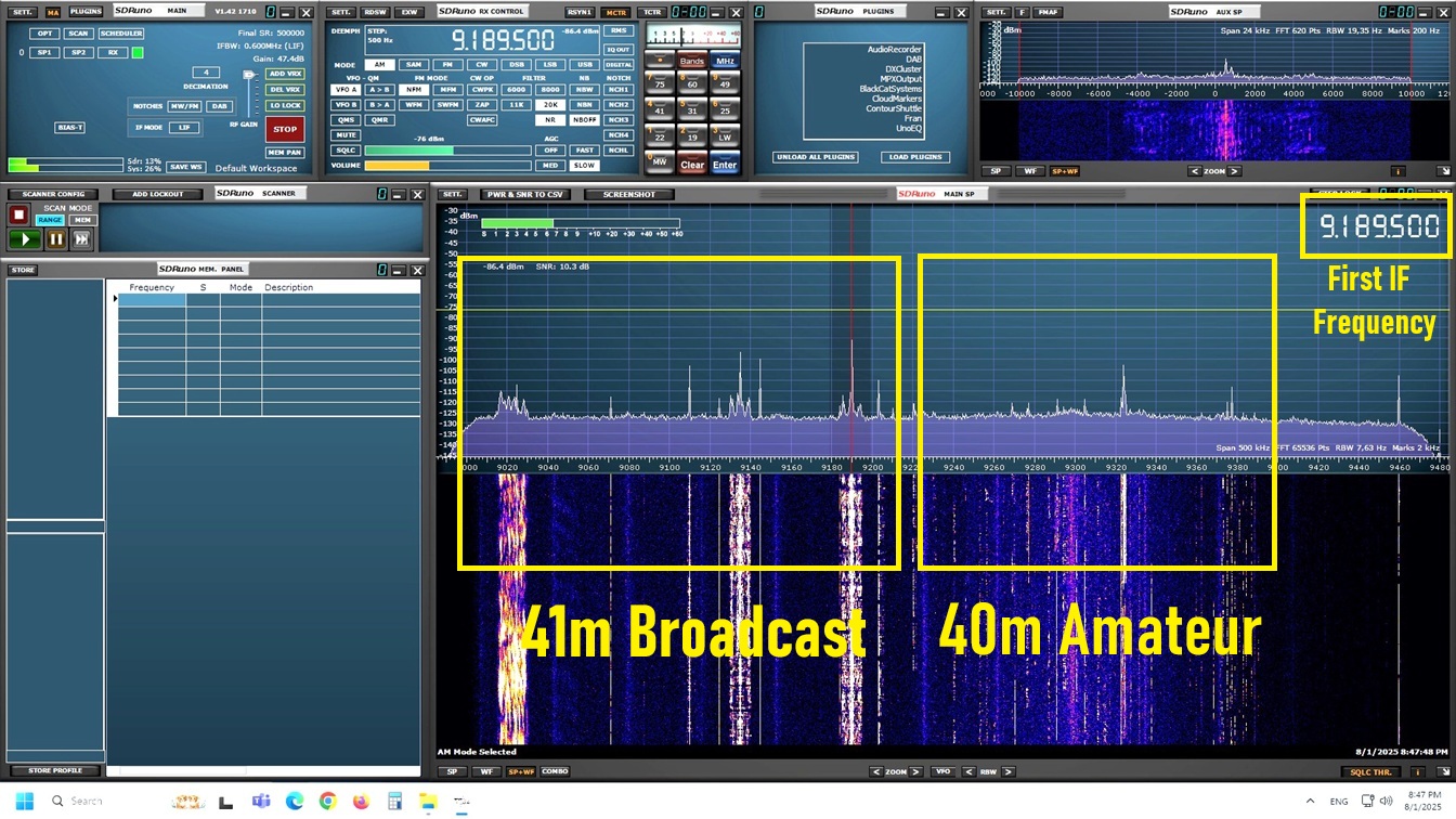
I took power from the mains transformer through a rectifier, and the output signal from the buffer comes out through this hole and should be connected to the Antenna input of the SDR receiver. Now we will look at the signal spectrum of the entire 41m Broadcast band, as well as the 40m Amateur band. In fact, these are the frequencies on which I had the best reception at the time of recording this video. First of all, on the SDR Uno software, we need to set the first IF frequency of the radio receiver, and in this case it is about 9.1 MHz and start SDRUno software. Now, we need to set the preselector knob of the radio to the position where we have the best reception. This is the spectrum of the entire 40m and 41m band.
We can select the desired signal, and with the help of the software, we can set many different parameters, which are almost impossible to change directly on the radio hardware. So in this case, we use only the input part of the radio up to the first IF transformer, and then all the electronics of the radio are replaced with the SDRPlay SDR radio and the appropriate software.
And finally a short conclusion. By integrating an SDR-based panadapter into my Trio JR500S, I’ve brought modern spectrum visualization to this classic tube radio. This upgrade enhances functionality while preserving the vintage charm of the receiver. If I now go back to the original tube receiver, we will see that I receive the same stations directly on the receiver, which is confirmation of the fact that the Buffer Amplifier does not affect the original input signal at all.


