


Story
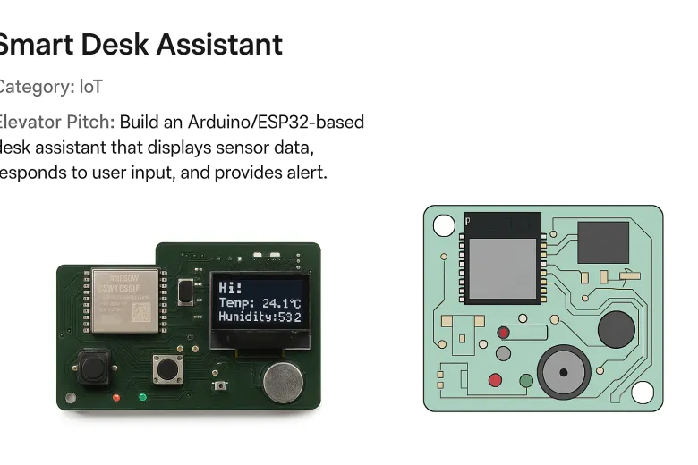
The Smart Desk Assistant is an intermediate-level project designed for Arduino and ESP32 enthusiasts who want to learn about sensors, displays, voice input, and interactive electronics. It combines multiple functionalities into a single desk gadget, making it a perfect learning tool and a practical desktop companion.
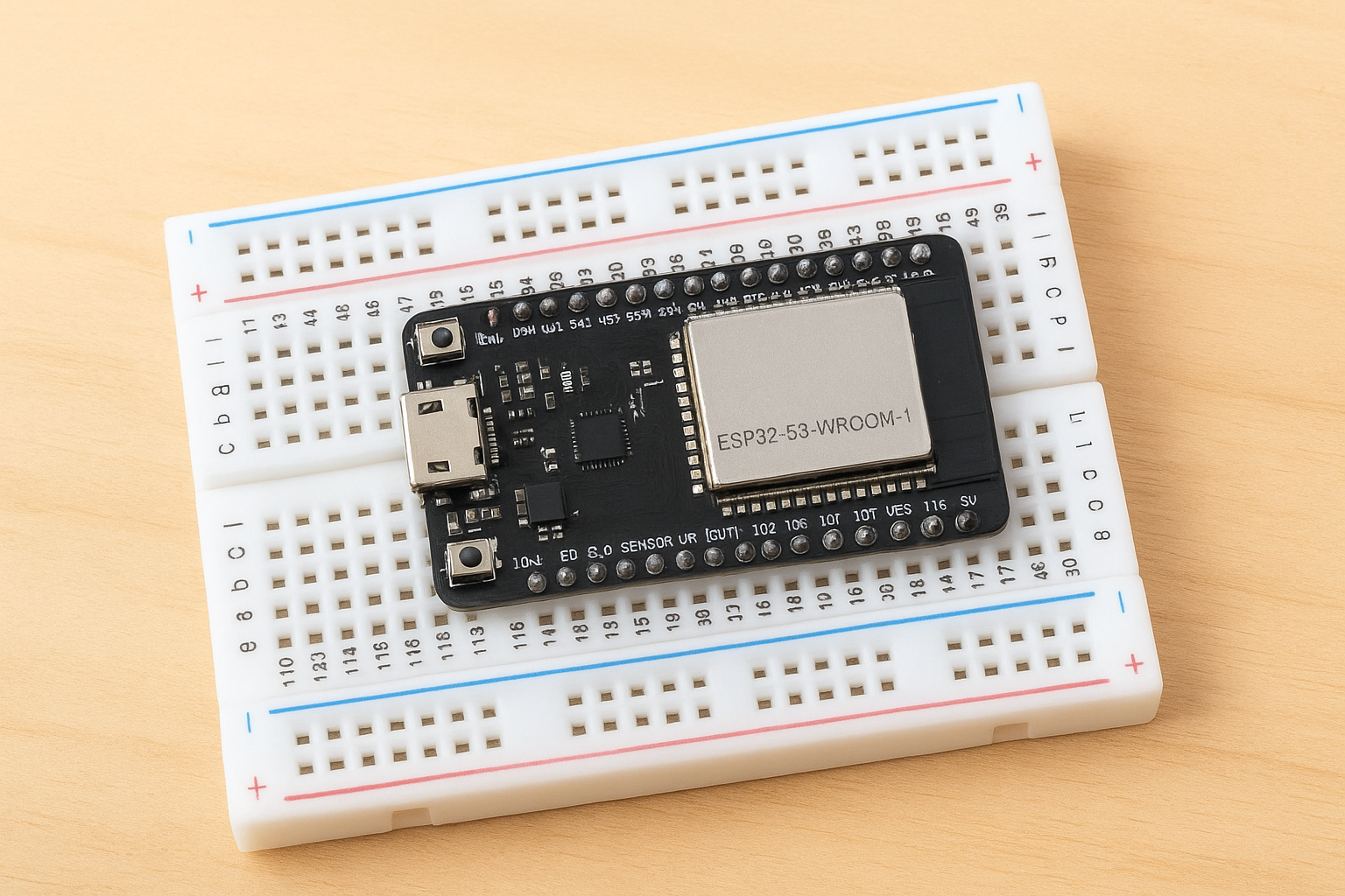
The core of the project is the ESP32-S3 microcontroller, which provides built-in Wi-Fi, BLE, and enough processing power to handle sensor data, LED controls, and voice input. Using the ESP32 allows users to explore both programming concepts and hardware integration while providing a scalable platform for future IoT projects.
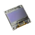
The Smart Desk Assistant is equipped with a DHT22 temperature and humidity sensor, which monitors environmental conditions. The data from the sensor is displayed on a 0.96" I2C OLED display, providing real-time updates. This introduces beginners to the I2C communication protocol, a common interface used in electronics for connecting microcontrollers with sensors and displays.
For user interaction, the project includes two push buttons that can trigger different actions, such as cycling through LED patterns or activating the buzzer. LEDs are included as visual indicators, connected through 220Ω resistors to prevent overcurrent. The LEDs provide immediate visual feedback when buttons are pressed or when sensor thresholds are reached.
An INMP441 MEMS microphone allows the ESP32 to respond to simple voice commands. While fully-fledged voice AI may require cloud services, the project teaches users the basics of digital audio input and processing on microcontrollers. A mini speaker can output simple audio feedback such as beeps or tones, adding an auditory dimension to interactions.
Optionally, a vibration motor can provide haptic feedback, making the assistant even more interactive. A USB-C or Micro-USB connector powers the device and allows easy programming, while decoupling capacitors (0.1µF) ensure stable voltage to the ESP32.
The project is designed for flexibility and expandability. Learners can start with basic button-controlled LEDs and gradually add the OLED display, sensor readings, and voice command functionality. This layered approach helps students understand each component and its integration without being overwhelmed.
From a hardware design perspective, users can build the project on a breadboard for prototyping or create a custom PCB using EasyEDA, which allows them to generate Gerber files for professional fabrication. A Pick-and-Place (CPL) CSV can be generated for automated assembly, making it easy to replicate the project. Assembly and test instructions ensure correct placement of components and verification of system functionality, including LED tests, button presses, sensor readings, and audio output.
For coding, the Arduino IDE or PlatformIO is used. Beginners learn how to read sensors, write values to an OLED display, control LEDs via PWM, detect button presses, and manage simple audio input/output. Additionally, the ESP32 can be programmed to send sensor data to a web server for IoT experiments, giving learners exposure to networked devices.
The Smart Desk Assistant encourages problem-solving, debugging, and iterative design. It is a comprehensive intermediate project that balances hardware and software challenges while being engaging and practical. Users will finish the project with a fully functional, multi-sensor desktop assistant and a strong understanding of intermediate Arduino/ESP32 concepts, ready to explore more advanced projects or IoT applications.
Step 1: Prepare Your Workspace
Clear a desk space and gather all components listed in the BOM. Make sure your ESP32 module, OLED display, LEDs, buttons, DHT22 sensor, microphone, speaker, capacitors, resistors, USB connector, and optional vibration motor are at hand. Use a small container to organize SMD or through-hole parts.
Step 2: Mount the ESP32 Module
Place the ESP32-S3-WROOM-1 module on your breadboard or PCB at the designated position. Ensure the antenna area is unobstructed. Check the orientation of the pins to avoid damage during soldering.
Step 3: Connect the Temperature & Humidity Sensor
Install the DHT22 sensor with correct orientation. Connect the VCC to 3.3V, GND to ground, and DATA pin to the chosen digital input pin on the ESP32. Double-check wiring to avoid reversed connections.
Step 4: Install the OLED Display
Mount the 0.96" I2C OLED display. Connect SDA to ESP32’s SDA pin, SCL to SCL, VCC to 3.3V, and GND to ground. Verify the pinout matches your module specifications.
Step 5: Place LEDs and Resistors
Install 2–3 status LEDs on the PCB. Connect each LED in series with a 220Ω resistor. Ensure correct polarity: the longer leg is the anode (+). Connect LEDs to the selected digital output pins.
Step 6: Install Push Buttons
Place two push buttons on the board. Connect one side to ground and the other side to ESP32 digital input pins, optionally using a pull-down resistor to ensure reliable readings.
Step 7: Add the Microphone
Mount the INMP441 MEMS microphone near the top edge, keeping it clear of metal obstacles. Connect power, ground, and data lines according to ESP32 I2S input requirements.
Step 8: Connect the Speaker
Install the mini speaker close to the amplifier output pins. Ensure correct polarity and confirm that the ESP32 pin chosen for audio output can drive the speaker or an amplifier.
Step 9: Optional Vibration Motor
If using the coin vibration motor, connect it to a digital output via a MOSFET or driver circuit. Ensure correct polarity and use a current-limiting method if necessary.
Step 10: Place Decoupling Capacitors
Install 0.1µF decoupling capacitors near ESP32 power pins. These help smooth voltage and prevent microcontroller resets.
Step 11: Connect USB Power/Programming
Install the USB-C or Micro-USB connector to supply power and allow programming. Verify the orientation and solder carefully.
Step 12: Initial Power-Up
Connect the board to USB power. Measure 3.3V at the ESP32 module pins to ensure correct voltage. Look for shorts before programming.
Step 13: Test Individual Components
-
Blink LEDs with a simple Arduino sketch.
-
Press buttons and read digital input via Serial Monitor.
-
Read temperature/humidity from DHT22 sensor.
-
Display test messages on OLED.
-
Test microphone input via I2S sample sketch.
-
Output audio to speaker to check tone playback.
-
Optional: trigger vibration motor to verify functionality.
Step 14: Upload Main Program
Once individual components are verified, upload your main Arduino sketch that integrates LEDs, buttons, DHT22 readings, OLED display updates, microphone input, and optional IoT features.
Step 15: Final Verification
Test full system functionality: LED patterns, button-triggered actions, temperature/humidity display, audio feedback, and vibration alerts. Adjust code if needed. Ensure stability during extended operation.
Step 16: Optional PCB Assembly
For a permanent version, use EasyEDA to generate Gerber files, CPL CSV for pick-and-place, and submit for fabrication via Elecrow. After assembly, repeat testing steps to ensure everything works correctly.![]()