Add to cart
Board Type : GerberFile :
Layer : Dimensions :
PCB Qty :
Different PCB Design
PCB Thickness : PCB Color :
Surface Finish : Castellated Hole :
Copper Weight : 1 oz Production Time :
Total: US $
Elecrow community is a shared platform and we are not responsible for any design issues.

PCB Assembly

PCBA Qty: BomFile:
NO. OF UNIQUE PARTS: NO. of Components:
Assembly Cost: US $
Elecrow community is a shared platform and we are not responsible for any design issues.
Add to cart
3dPrintingFile : Size :
Unit : Volumn :
3D Printing Qty : Material :
Total: US $12.99
Elecrow community is a shared platform and we are not responsible for any design issues.
Add to cart
Acrylic Type : AcrylicFile :
Dimensions: Engrave:
Acrylic Qty :
Acrylic Thickness:
Acrylic Color:
Total: US $12.99
Elecrow community is a shared platform and we are not responsible for any design issues.
Add to cart
CNC Milling File : Size:
Unit: Volumn:
CNC Milling Qty : Material:
Type of Aluminum: Surface Finish:
Tolerance:
Surface Roughness:
Total: US $12.99
Elecrow community is a shared platform and we are not responsible for any design issues.
closed
user-img

cris

Published: Oct 17,2024

Adjust Pulse Width Modulation using NE555 and Mosfet

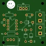
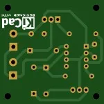
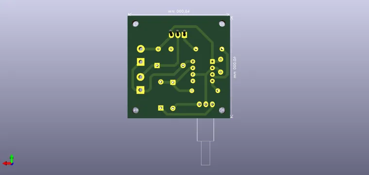
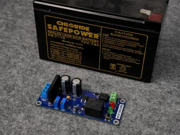
This a simple circuit, very easy to build and also efficient. There is enough space for mounting a heat sink, you may want to use a IRFZ44N instead.

ccc ccc
Copyright Info

Attribution-ShareAlike (CC BY-SA)

Read More⇒
  192
  2
  0
cover-img
 
  • thumbnail-img
  • thumbnail-img
  • thumbnail-img
  • thumbnail-img
 

Hardware Components

  • NE555P

    X 1 fenxiang
  • IRF540

    X 1 fenxiang

Tools, APP Software Used etc.

  • Kicad

Story

Adjust Pulse Width Modulation using NE555 and Mosfet

One of the most fundamental problems in robotics is controlling the speed of a DC motor. The most common method of speed control is PWM, or pulse width modulation. pulse width modulation is the process of changing the power in a switching device at a given frequency. These switchings on and off are called "Duty Cycle". The diagram below shows the 10%, 50%, 90% Duty Cycle waveforms.

https://electrodb.ro/control-turatie-motor-prin-varierea-factorului-de-umplere-pwm/

So, Duty Cycle describes the width of a pulse in percentage. A Duty Cycle of 10% means that during 10% of a cycle our generator receives current compared to 90% of the time when it does not. A Duty Cycle of 100% means that our generator receives current all the time and we would not need a PWM.

These signals are sent to the motor at a high enough frequency that the pulsation has no effect on the motor. The end result of the PWM process is that the total power sent to the motor can be adjusted from (0% Duty Cycle) to (100 Duty Cycle), with good efficiency and stable control.

The 555 timer in the PWM circuit is configured as an astable oscillator. This means that once power is applied, the 555 will oscillate without any external triggering. Before the technical explanation of the circuit, let's look at the 555 timer diagram.


P.S. I am not the original author of this circuit I just draw it.

Enjoy it!

Schematic and Layout
user-img

cris

+ Follow

Topic

View All
ne555 pwm
  • Comments( 0 )
  • Like( 2 )
/1000
Upload a photo:
You can only upload 1 files in total. Each file cannot exceed 2MB. Supports JPG, JPEG, GIF, PNG, BMP

You May Also Like

View All