
Story
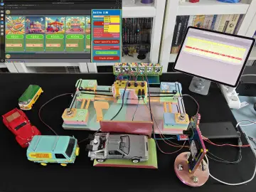
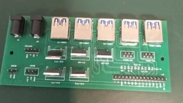
ANPR Access Control PCB with IR Sensors
1. Define Objective
-
Design a custom PCB for an ANPR vehicle access system.
-
Interface with Raspberry Pi 4 to control:
-
Traffic lights
-
Buzzer
-
Gate motor
-
RFID module
-
IR sensors for vehicle detection
-
2. Select Components
-
Headers (1x2, 1x4, 1x15, 3x1) – for modular connections
-
5.5mm DC Jack – 12V power input
-
1kΩ Resistors – for MOSFET gate pull-down
-
IRLZ44N MOSFET + Heatsink – for switching loads
-
Molex 48393-0003 Connector – secure 3-pin connections
-
IR Sensors – for detecting vehicle presence
-
Raspberry Pi 4 – main controller via GPIO
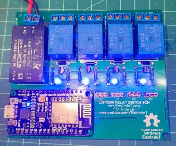
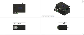
3. Design the PCB
-
Route 12V input and distribute power
-
Add headers for all peripherals (RFID, buzzer, lights, gate, IR sensors)
-
Connect MOSFETs to control high-current devices
-
Add GPIO header (1x15) for Raspberry Pi
4. Interface Raspberry Pi
-
Use GPIOs to:
-
Read IR sensor signals
-
Read RFID tag
-
Control gate, buzzer, and traffic light
-
-
Process ANPR camera feed over LAN
5. Manage Power
-
Input: 12V via DC jack
-
Output:
-
12V for motors/lights
-
Optional 5V for logic-level devices (e.g., RFID, IR sensors)
-
6. Test System
-
Check individual components (IR, RFID, MOSFET switching)
-
Run Raspberry Pi code for full system logic
-
Validate vehicle detection, authentication, and gate control
7. Deploy System
-
Mount PCB and components securely
-
Connect to gate hardware and ANPR camera
-
Run live Python-based control from Raspberry Pi