Story
A code lock is a keyless security device—either mechanical or electronic—that restricts access to doors, lockers, or cabinets using a preset numerical code entered via a keypad. They eliminate the need for physical keys, allow for quick code changes, and can range from simple push-button mechanical models to advanced, smart-enabled devices.
This time I will show you the simplest possible way to make such an advanced device, at the same time incredibly simple thanks to the beautiful CrowPanel 1.28 inch-HMI ESP32 Rotary Display. In one of the previous videos I presented you a way to make a variable frequency oscillator with this small display and there all its features and functions are described.
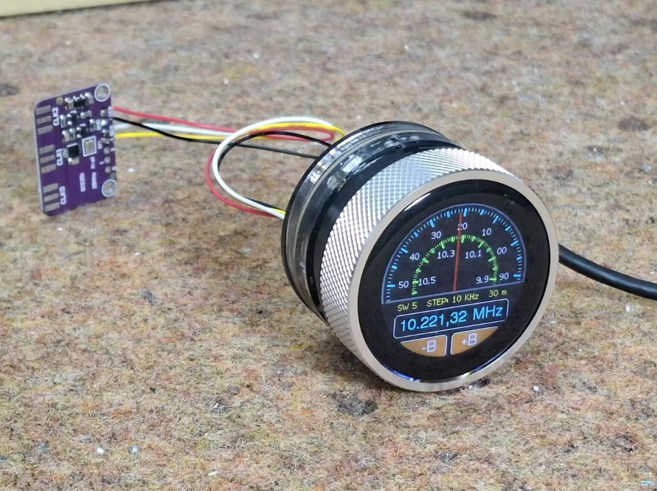
In addition to the touch function and button, this module also contains a rotary encoder which makes it ideal for the device described in this video. Also, the Access Point function of the ESP32 MCU allows us to control it via Wi-Fi with a Smartphone.
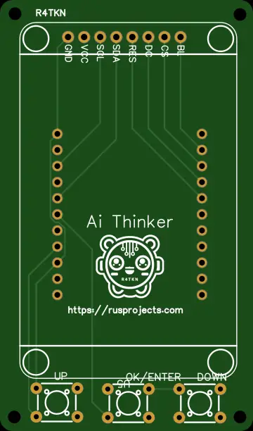
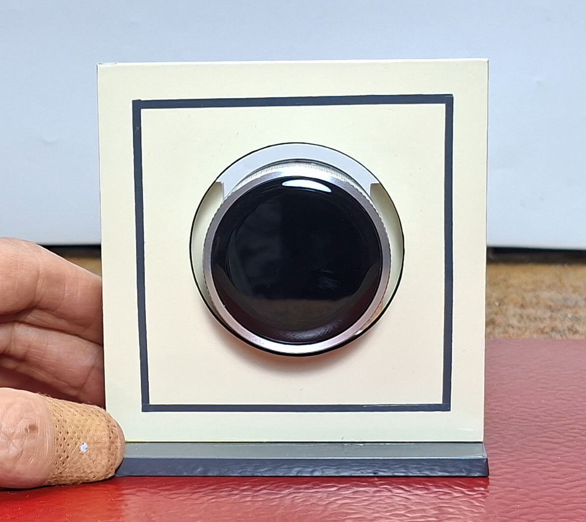
As I mentioned earlier, in this particular example I am using only a Crowpanel round display and will focus on the software part, which also means that there will be no need for soldering and connecting external components. However, in the case of a real lock, an I2C controlled relay or an I2C port expander with a standard relay should also be installed. For better visibility, the display module is mounted on a small PVC housing covered with self-adhesive wallpaper.
Let me not forget to mention that this is actually a final exam project of a student from a vocational high school under my mentorship. In fact, my part of the code is only a small modification of the library as well as the way the display is initialized and managed. The remaining functional part of the code was completely developed by the student using the Free AI client.
It is important to emphasize that in order to compile the code without errors, you need to use ESP32 Core V 2.0.14 along with the provided libraries, and I specifically used Arduino IDE version 1.8.16. Otherwise, from the very beginning, the idea was to develop the code in a way that in the future we could very easily change many of the parameters that were defined at the beginning.
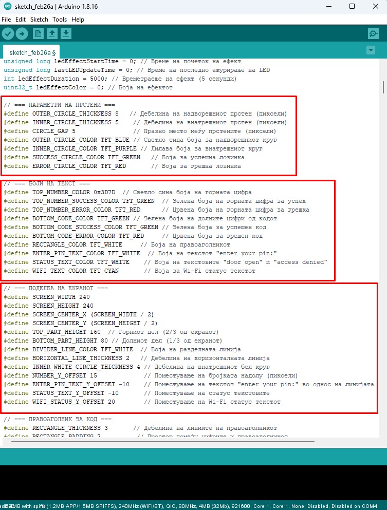
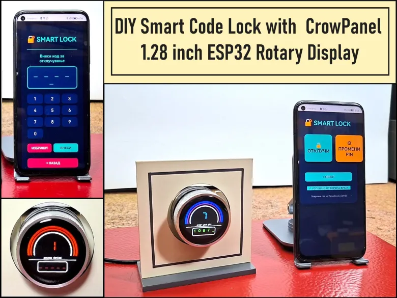
Now let's see how this device works in real conditions. When the lock is turned on, the image appears on the display, which is divided into two parts. In the upper part, the specific number is entered, and the lower half is reserved for the complete password. In this demo case, the entered password will be visible, otherwise in real use only asterisks would appear here. We select the number by turning the rotating display, and confirm it by pressing the button. If we enter the wrong password, the frame around the number lights up red for the next 5 seconds, the display says Wrong Password, and a red LED rotates in the background around the display.
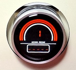
Conversely, if the password is entered correctly, the frame lights up green, a message on the display for the correct password, and a green LED rotates in the background of the display. During this Green period of 5 seconds, we have the opportunity to open the door. In a real case, by activating the green LED, a relay was also activated that unlocked the door.
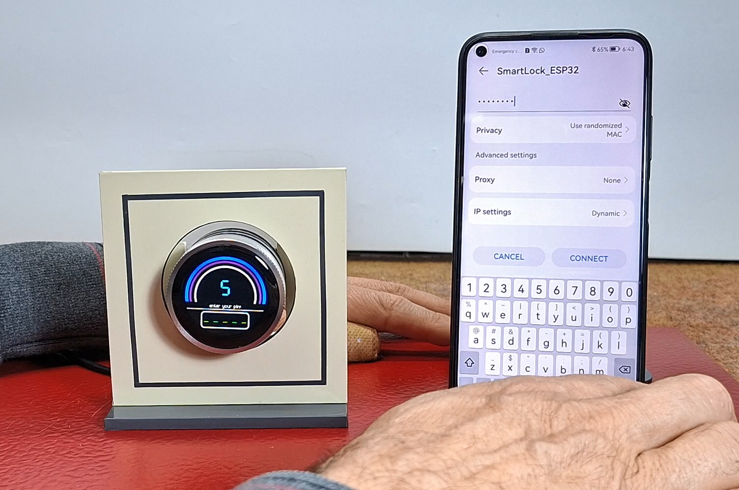
I also mentioned that we will use the access point option of the ESP32 microcontroller, which makes this lock a Smart device. The code has created a simple web interface through which the lock can be controlled. First, we need to connect to the Wi-Fi network with the name "SmartLock_ESP32" and the password "12345678" with a smartphone (we define these credentials in the code).
Then we enter the address 192.168.4.1 in the web browser and by opening this address a beautiful control interface appears. Here, at the beginning, we can choose one of the two offered options: to open the lock, or to change the master password.
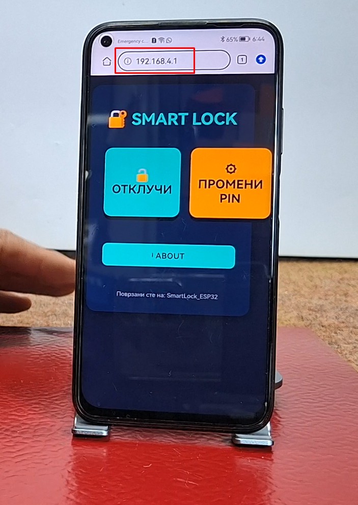
If we enter "open lock", a keyboard appears through which we need to enter the code. The same signaling applies here as with mechanical entry as far as colors are concerned. If we want to change the master password, we enter the change password menu.
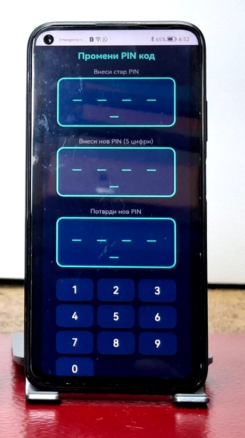
There we have the option to first enter the existing password, and then we need to enter and confirm the new changed password. If the existing password is entered correctly, the successful password change will be signaled by a circular movement of the blue LED in the background of the display.
And finally a short conclusion. This project proves that with the right HMI hardware and a bit of coding, you can create a high-end security interface that rivals professional systems in both look and feel. It is a perfect example of how modern microcontrollers can simplify complex mechanical tasks into elegant digital solutions.