Story
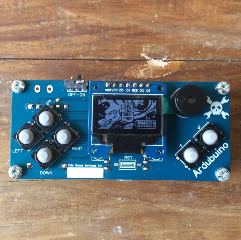
This project is a continuation of my previous ardubuino project. Which was an Arduboy compatible game console
Eventhough it has the same size and dimension from the previous version, the PCB design is differrent and this is a collaboration project with a fellow local maker, Andi Dinata.
The main focus of this project is teaching kids how to make their own game console trough an affordable workshop held by my friend. with that in mind I design the PCB to be easy to solder with through hole design and minimum components to use.
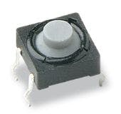
The main different on component side is the button, we have selected a few buttons option and end up using the soft tactile button because it's comfortable to press
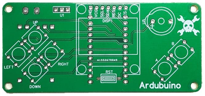
another update on the PCB is an easy to solder battery pad that connected directly to the tp4056 charging module. After tweaking for two week this is the Final Design of the unpopulated ARDUBUINO V3 PCB
Building Guide
if you want to build your own ardubuino, you can print the PCB using the gerber File below at file section. On this page I will guide on how to solder the components for beginner if you did not have any experience soldering before
1. Prepare The tools and soldering basics
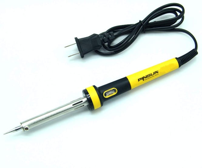
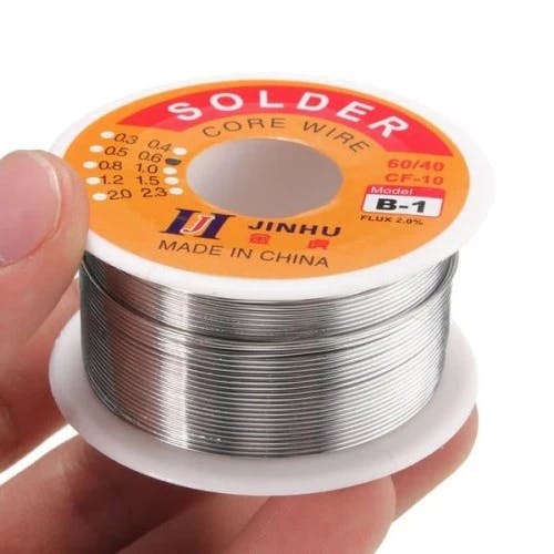
Use a regular soldering iron with the minimum power at 20 watt. Also prepare your solder flux, it is not mandatory but it will help your soldering experience less frustating. Also prepare a soldering brass/sponge to clean your soldering.


After preparing the tools need, this is simple guide card how to solder correctly
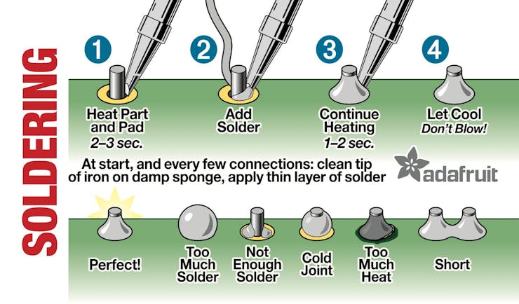
Another important thing while soldering is always be mindful with your soldering iron due to its extreme heat
2. Soft Tactile Button
The first thing to solder is the buttons, before soldering the buttons, straighten up the button's leg so it will be easy for you to insert the button to the PCB and follow the picture below for the button soldering sequence

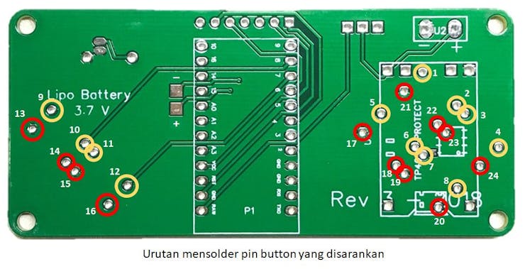
The red circle are the Ground pad, it will take more heat to solder, so take your time when solder those pads
3. Buzzer
Another easy to solder components are buzzer. It has to legs, one short leg (negative leg) and one long legs (positive leg). Solder the legs according the sign on the PCB
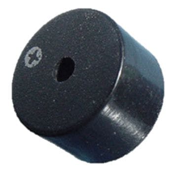
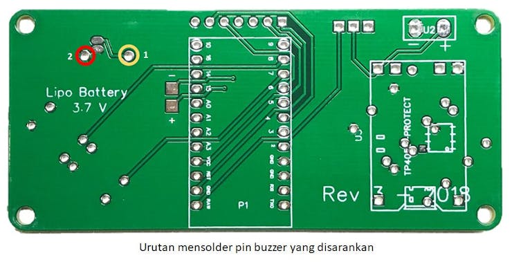
the red circle indicate the ground pad (negative leg). it has the same soldering treatment as the button
4. Arduino Pro Micro
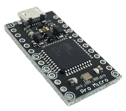
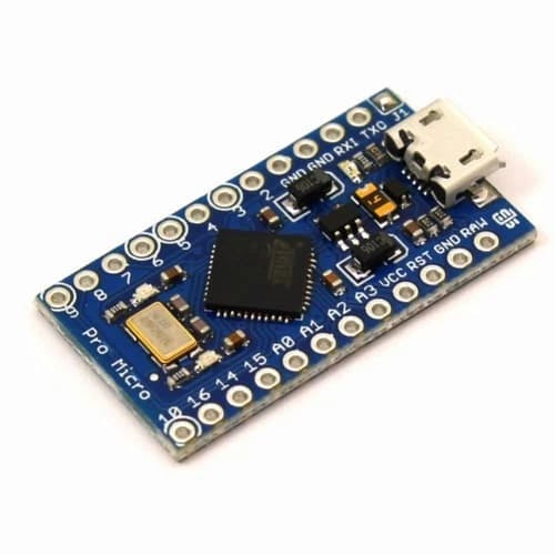
There are two version of arduino pro micro on the market. the black one and the OG pro micro from Sparkfun, the main difference is on the IC package, one using TQFP and the other one is QFN. You can use both of this pro micro version for this PCB.
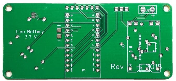
Take note that the Arduino Pro micro module is placed on the backside of the PCB and using the orientation below
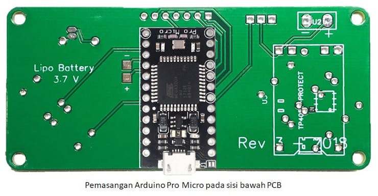
Follow the soldering sequence below for easy soldering
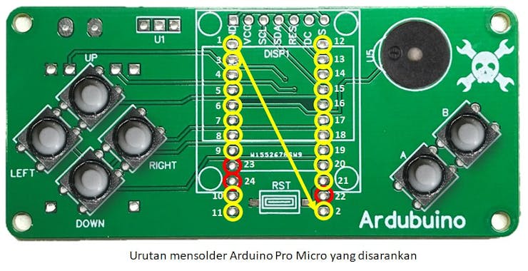
Red circle are the ground pads
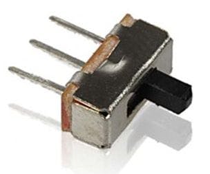
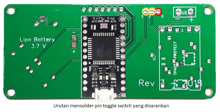
5. Toggle Switch
After soldering the MCU flip the PCB on the back side again to solder toggle switch and follow the guide below
6. Charging module
For the charging module I am using the generic power bank TP4056 module with the pinout below
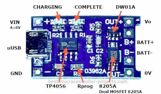
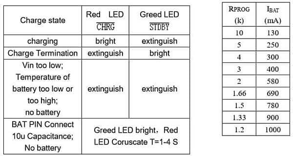
Take note on the Rprog section, by default the value of the resistor 1.2K ohm and it was meant to charge 1000 mA capacity lipo battery. But if you want to use a smaller capacity you might wanna change the Rprog resistor to prevent overcharging. To my experience I am not having an issue using a 300 mA with the default 1.2K Rprog, but if you want to be more cautious you can follow the guide below to change the Rprog
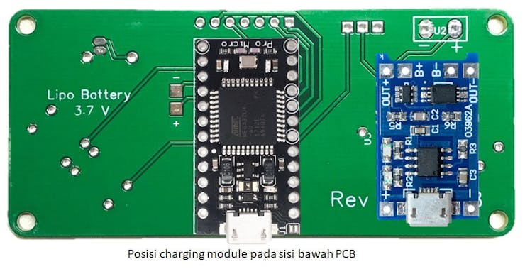
Put the charging module on the back of the PCB
flip the PCB, on the front side PCB solder the charging module's legs using the sequence below
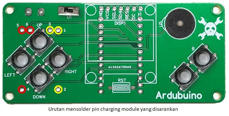
Red Circle are ground pads
7. Oled Display
for this PCB I am using a 0.96 inch 7 leg SPI oled
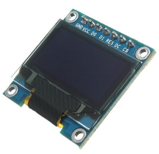
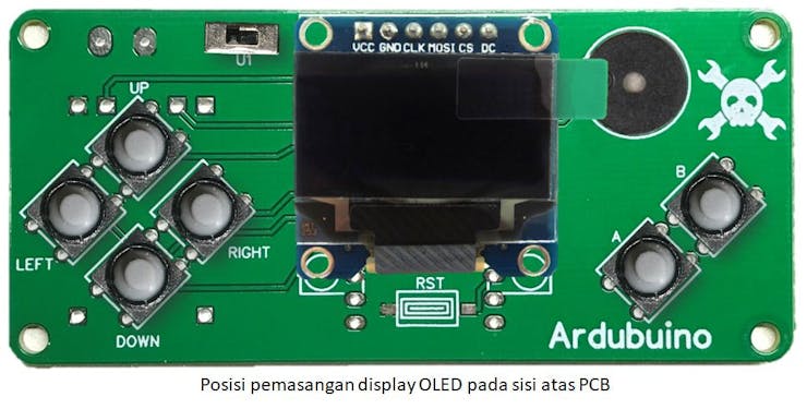
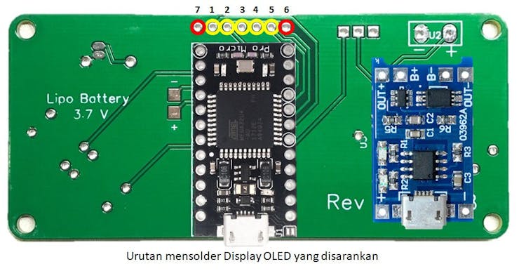
Put the oled module on the front side of the PCB and then flip the PCB to solder oled according to this sequence
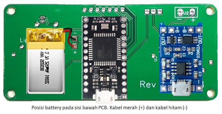
8. Lipo Battery
This is the last part to solder and need extra attention because you need to make sure that the two cable of the battery do not make contact when preparing to solder or it will damage your battery.
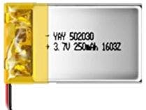
As told you before at the charging module section, it is recommended to use the lipo battery with the Rprog accordingly. Mostly the 1000 mA has bigger size and it will overhang on the backside of the PCB. I am suggesting using below 300 mA lipo battery due its small size.
The battery has two cable red (positive) and black (negative). Just solder cable accordingly to the PCB pads
After this you are prepared to use the ardubuino to play the arduboy games
9. Upload a game
To upload a game you need to install an Arduino IDE, I will not show on how to install because there are already a ton of guide on how to install to your computer.
After you install the Arduino IDE, you need to install the driver for the Arduino Pro Micro, you can google it or you can grab it on this link.
open your device manager to check the device is connected properly or not
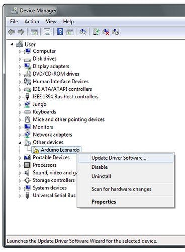
If the device manager show you the arduino Leonardo, no need to worry. because the pro micro and leonardo are using the same MCU which is the ATMega32u4. right click on the device and choose update driver software
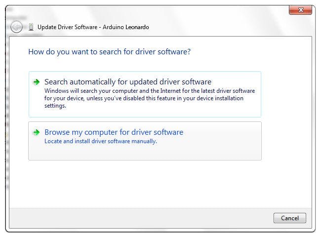
choose Browse my computer and open the driver software you just downloaded
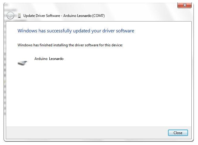
click next until the driver give you the COM port address
Next we need to install the Arduboy library on the Arduino IDE. Open the Arduino IDE and open the library manager
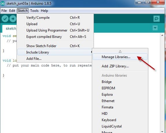
and install the following library to the IDE
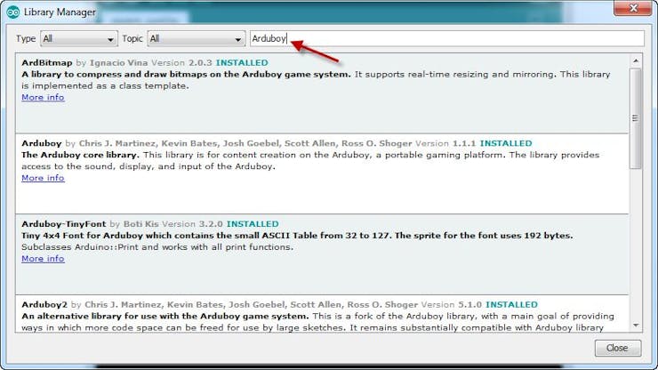
- ArdBitmap
- Arduboy
- Arduboy2
- Arduboy-TinyFont
- ArduboyPlaytune
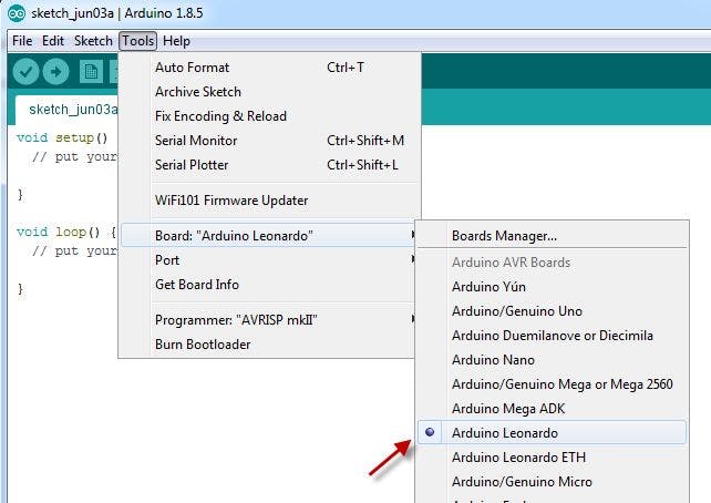
After installing the necessary library open the Board Manager and choose Arduino Leonardo as your target device
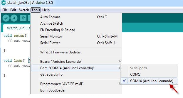
And then choose the port according the COM port given on the device manager
To try an example game open the menu structure below
File-->Examples-->Arduboy-->ArduBreakout
And the upload it to your new console. After uploading is done enjoy your hardwork building the console.
Arduboy has more than 200 compatible games, and you can download it from