

Story
Modern IoT systems usually depend on Wi-Fi, cloud platforms, or mobile networks. But what if you need to control a device in a location where internet access is unreliable or completely unavailable?
Imagine controlling lights in a remote warehouse, or operating electrical equipment from far away — all directly from your smartphone.
That is exactly where LoRa communication technology becomes extremely powerful.
In this project, we will build a long-range wireless appliance control system using an Arduino Nano and the RYLR999 LoRa + BLE module. The system uses Bluetooth Low Energy (BLE) for smartphone interaction and LoRa wireless communication for transmitting commands across very long distances.
Using this setup, we will remotely control:
- A 240V AC bulb
- A 12V DC fan
The project also includes:
- Real-time LCD status monitoring
- Relay-based appliance switching
- Bi-directional command acknowledgment
- LoRa + BLE hybrid communication architecture
This project demonstrates how powerful embedded communication systems can be created without relying on cloud infrastructure.
How the System Works
The complete system is divided into two independent hardware units:
1. Controller Unit
The controller side acts as the interface between the smartphone and the LoRa network.
An Android smartphone connects to the RYLR999 module using Bluetooth Low Energy through the LightBlue BLE application. Whenever the user sends a command such as turning a bulb or fan ON or OFF, the command is first received by the BLE interface of the RYLR999 module.
The Arduino Nano connected to this module reads the incoming BLE command and forwards the same instruction through the LoRa communication interface.
The LoRa module then transmits the data wirelessly over long distances.
2. Target Unit
The target side continuously listens for incoming LoRa transmissions.
A second RYLR999 module receives the wireless command and forwards the received data to another Arduino Nano.
The Arduino interprets the received command and activates relay outputs connected to electrical appliances.
In this project:
- Relay channel 1 controls a 240V AC bulb
- Relay channel 2 controls a 12V DC fan
Once the operation is completed successfully, the target node transmits a confirmation response back to the controller node.
RYLR999 Module
The most unique part of this project is the RYLR999 module.
Unlike traditional LoRa modules, the RYLR999 integrates:
- Bluetooth Low Energy communication
- Long-range LoRa radio communication
inside a single compact module.
This makes it possible to convert short-range smartphone BLE commands into long-range LoRa transmissions without needing separate communication hardware.
The module operates in two different communication layers:
BLE Layer
Used for direct smartphone communication.
LoRa Layer
Used for transmitting commands across long distances.
This architecture creates a highly flexible wireless control system suitable for industrial and IoT applications.
Source reference:
Hardware Components Used
The following components are required to build the project:
- Arduino Nano boards
- RYLR999 LoRa + BLE modules
- 3.3V to 5V bidirectional voltage level shifter
- 16×2 I2C LCD displays
- 2-channel relay modules
- Jumper wires
- 12V power adapter
- 240V AC bulb
- 12V DC fan
Controller Wiring Explanation
![]()
The controller setup consists of an Arduino Nano, an RYLR999 module, a voltage level shifter, and an I2C LCD display.
The RYLR999 module communicates with the Arduino using UART serial communication. Since the Arduino Nano operates at 5V logic levels and the RYLR999 module uses 3.3V logic, a bidirectional voltage level shifter is necessary to safely interface both devices.
The VDD pin of the RYLR999 module is connected to the 5V output of the Arduino Nano, while the GND pin connects to the common ground.
For LoRa communication, the TXD_LoRa pin of the module is connected to the LV2 pin of the level shifter, and the corresponding high-voltage output connects to the RX pin of the Arduino Nano. Similarly, the TX pin of the Arduino is routed through another level-shifter channel and connected to the RXD_LoRa pin of the module.
The BLE_TX pin of the Arduino connects through the voltage level shifter to the RXD_BLE pin of the RYLR999 module, while the BLE_RX pin connects through the level shifter to the TXD_BLE pin of the module.
The voltage level shifter itself requires both voltage references to function correctly. Therefore:
- HV pin connects to Arduino 5V
- LV pin connects to Arduino 3.3V
A 16×2 LCD with an I2C interface is connected to the Arduino for real-time monitoring.
The LCD connections are simple:
- VCC → Arduino 5V
- GND → Arduino GND
- SDA → Arduino A4
- SCL → Arduino A5
The LCD displays:
- System initialization messages
- BLE command reception
- LoRa transmission status
- Confirmation responses from the target node
This makes system debugging significantly easier.
Source reference:
Detailed Target Wiring Explanation
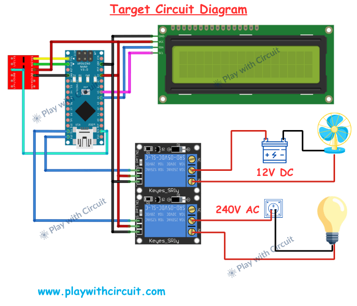
The target setup is very similar to the controller setup, except that BLE communication is not required here.
The RYLR999 module continuously listens for incoming LoRa messages and forwards received data to the Arduino Nano.
The LoRa TX and RX lines again pass through the bidirectional voltage level shifter before connecting to the Arduino serial pins.
The target node also includes a relay module used for appliance control.
The relay module is powered directly from the Arduino Nano:
- Relay VCC → Arduino 5V
- Relay GND → Arduino GND
The relay input pins are connected to digital output pins of the Arduino:
- D11 controls the bulb
- D12 controls the fan
When the Arduino receives a valid command, it activates the appropriate relay channel.
For the AC bulb, the relay switches the live wire of the AC mains supply. The AC source line is connected to the common terminal of the relay, while the normally open terminal connects to the bulb.
When the relay activates, the contacts close and allow AC current to flow to the bulb.
For the DC fan, the relay is connected in series with the positive 12V power line. Activating the relay completes the circuit and powers the fan.
The target setup also includes a 16×2 I2C LCD connected using the same A4 and A5 I2C pins of the Arduino.
This LCD displays:
- Received LoRa commands
- Relay activation status
- System response messages
⚠️ Since the system switches 240V AC loads, proper electrical safety precautions must always be followed while wiring the relay circuit.
Source reference:
Command Structure Used in the Project
The smartphone sends commands using the LightBlue BLE application.
The following command structure is used:
*L1#  → Turn bulb ON
*L0#  → Turn bulb OFF
*F1#  → Turn fan ON
*F0#  → Turn fan OFF
The controller extracts the payload and forwards it through LoRa communication.
The target node interprets the received command and performs the requested action.
After execution, the target sends a confirmation response:
DONEAlthough the payload appears simple, the actual LoRa transmission includes additional AT-command formatting such as destination address and payload length required by the RYLR999 communication protocol.
Source reference:
Why This Project Matters
This project demonstrates how powerful wireless systems can be built without depending on internet infrastructure.
Using LoRa communication makes it possible to create:
- Smart agriculture systems
- Long-range industrial monitoring
- Remote infrastructure control
- Wireless automation networks
- Off-grid IoT systems
The combination of BLE and LoRa also creates an intuitive user experience while maintaining excellent communication range.
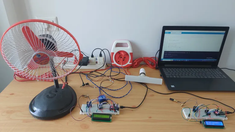
Testing
Full Project Resources
The complete project including:
- Full Arduino source code
- Circuit diagrams
- LoRa AT configuration
- Troubleshooting guide
- Range testing
is available at Play with Circuit