Story
Software-defined radio (SDR) is a radio communication system where components that have traditionally been implemented in analog hardware (such as mixers, filters, amplifiers, modulators, and demodulators) are instead implemented by means of software on a computer or embedded system. The biggest advantage of SDR is its flexibility. Because the functions are handled by software, you can change the radio's behavior by simply updating the software.
This time I will present you a wonderful example of how to make such a receiver using Raspberry Pi Pico.
Detailed video description at: https://youtu.be/Na7AuNM6LJE
Even this receiver works completely independently without the use of a PC and all functions are controlled directly on it and displayed on a small OLED display. The original project is presented on the 101 things website and the author is Jon Dawson (https://101-things.readthedocs.io/en/latest/breadboard_radio.html), so all credits go to him. Also there are many more exelent Raspberry Pi Pico projects on this site and I hope to test and promote some of them in the near future.
The receiver consists of a minimal number of components, but its huge number of functions and possibilities for various settings can rival even expensive commercial devices of this kind.
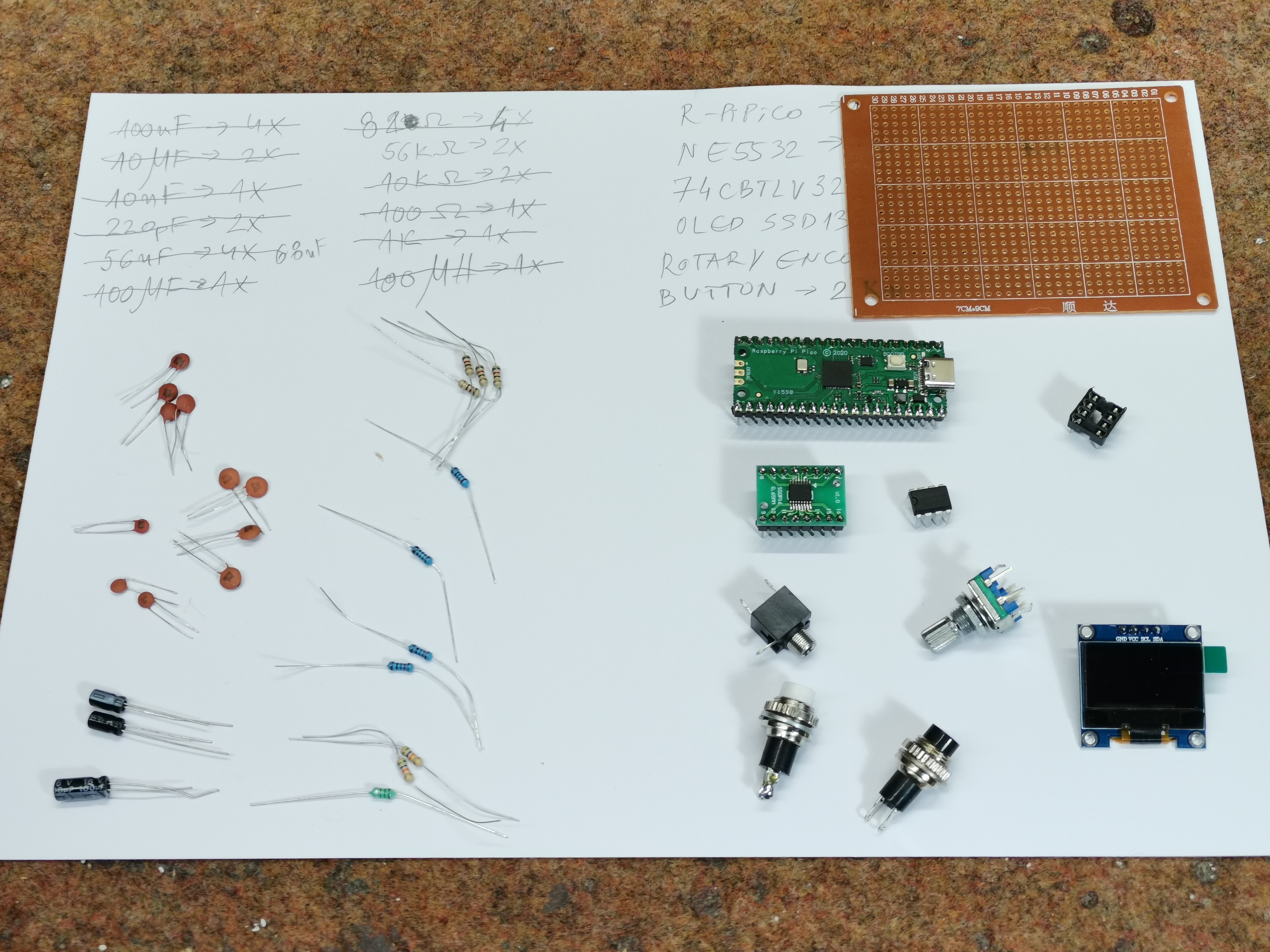
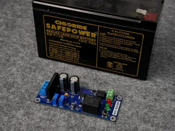
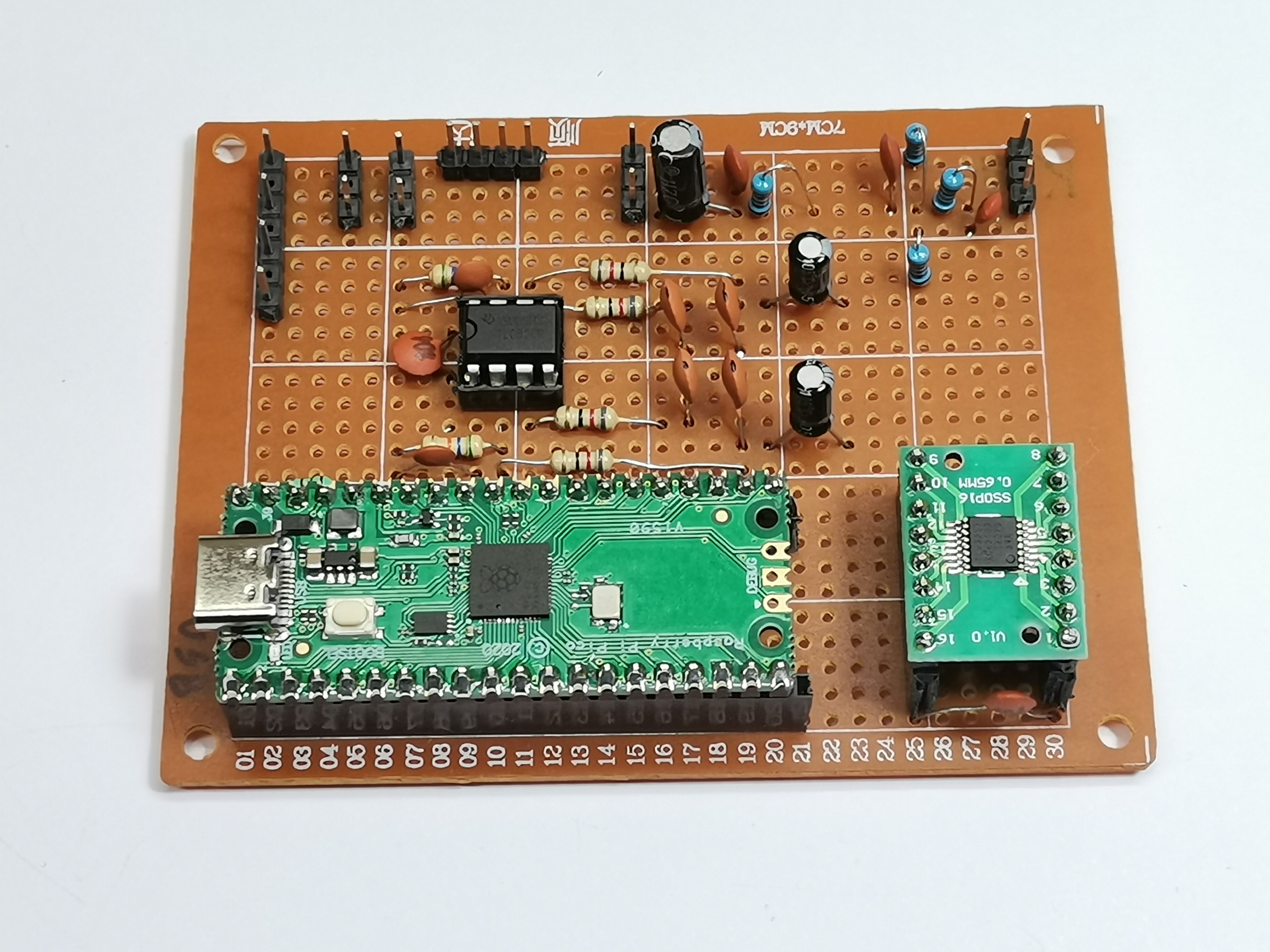
I made complete device on a universal PCB, and as you can see, the layout of the components is almost identical to the breadboard version of the schematic presented on the source page. I made the complete project on PCB in less than a day and was positively surprised by the fact that the device worked immediately upon first powering on.
The basic components are clearly visible and they are:
- Raspberry Pi Pico module
- CBTLV3253 Multiplexer IC
- TL082 Dual Operational Amplifier IC (I use it instead of MCP 6022, and NE5532 can also be used)
- SSD1306 OLED Display
- and rotary Encoder and two buttons
Now just a few words about installing the code. The GitHub page provides binaries for the Raspberry Pi Pico and the newer Raspberry Pi Pico2, in the form of a .uf2 file. This means that the installation is extremely simple. We need to hold down the button on the Pico and plug in the USB. Now the Pico is presented in "This PC" as a mass storage device and we need to simply copy the provided .uf2 file into it.
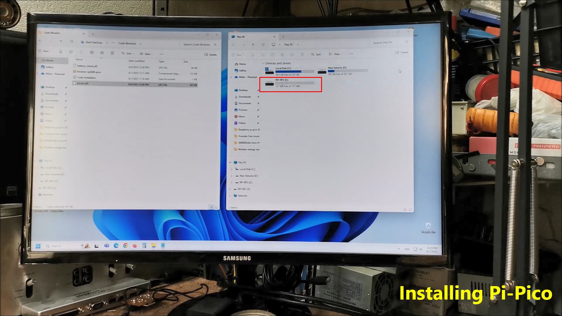
With this, the installation of the code is complete.
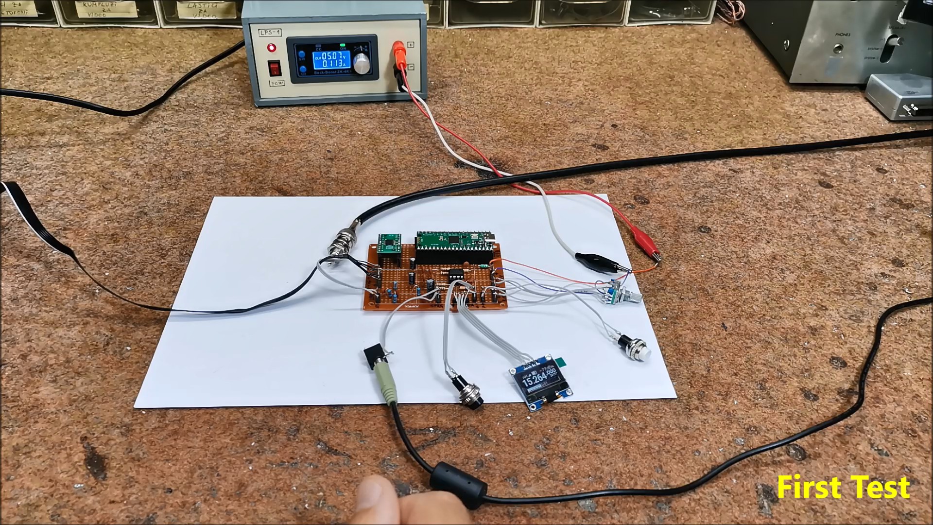
Now comes the first power-up of the device and a short test. I connected the audio output from the receiver to the "Line In" input of the PC sound card. For now, I connect a simple "long wire" antenna and try to receive a Broadcast station to confirm the functionality.
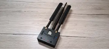
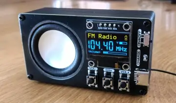
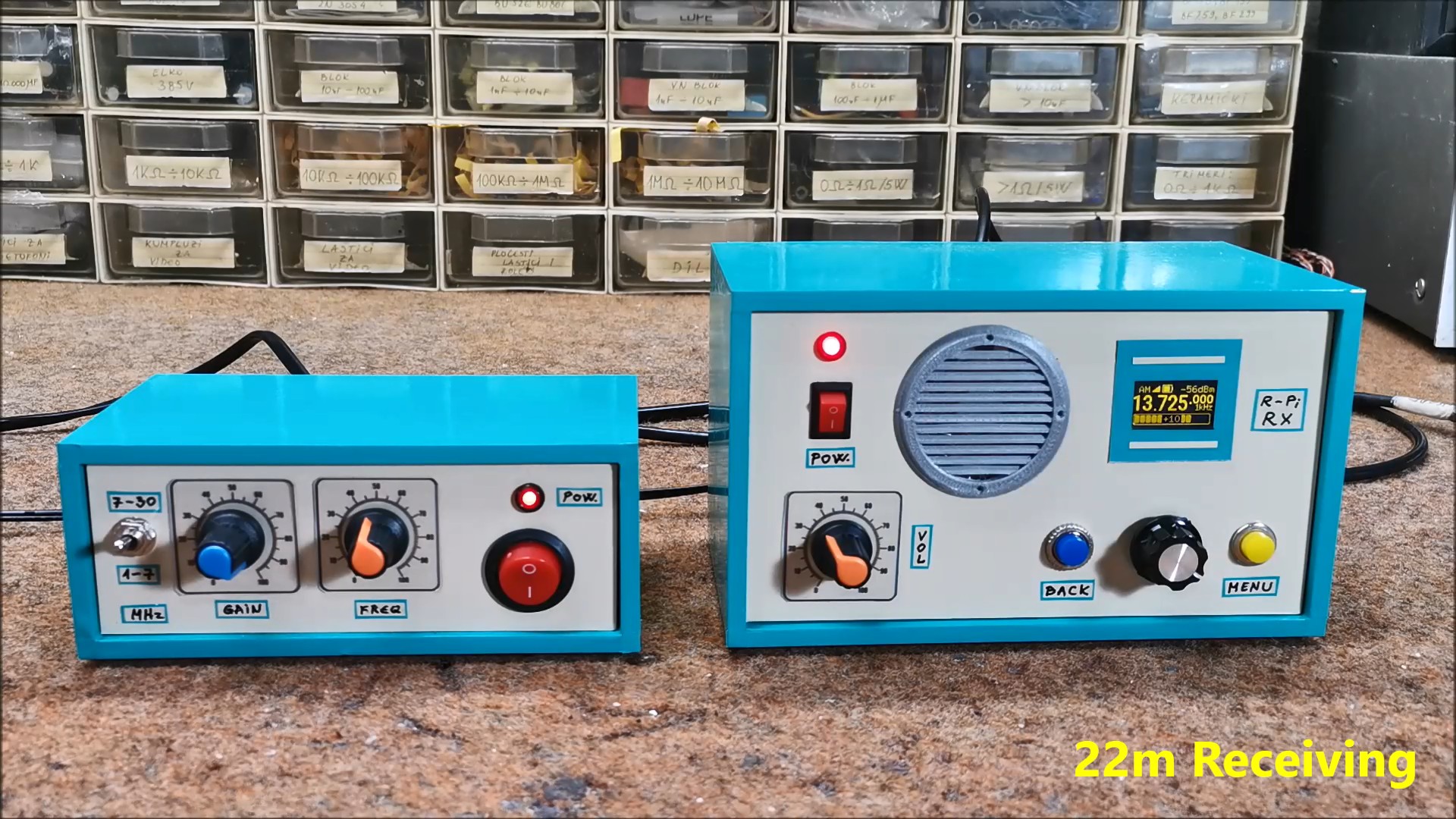
This is what the finished Pico SDR Receiver looks like placed in a suitable housing with the Display and control buttons on the front panel and the power and antenna connection on the back.
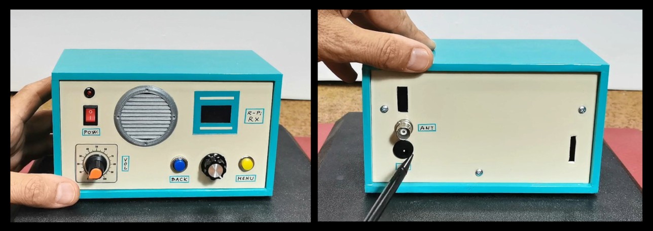
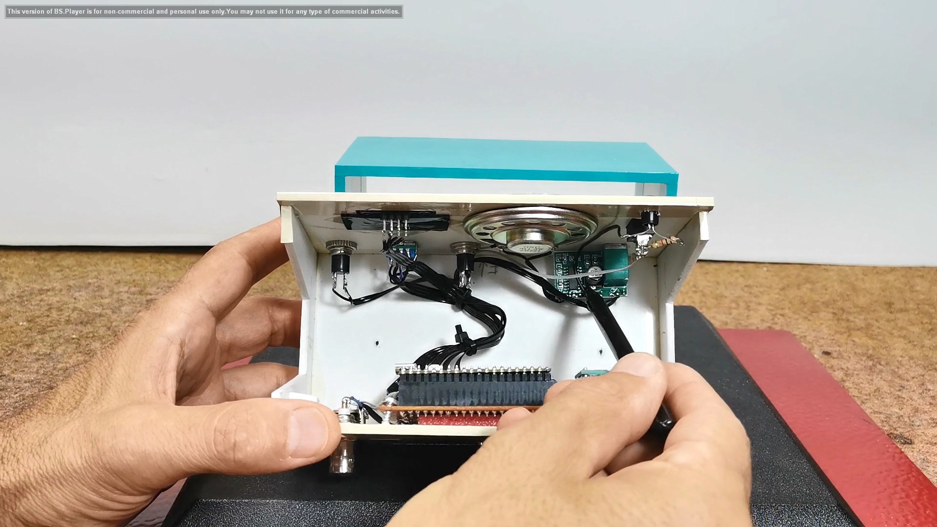
If we look inside the box we will see that in addition to the universal PCB it also have a D-class Audio Amplifier module along with a small speaker so the SDR receiver is completely independent keeping in mind that instead of an external power supply we can install Lithium batteries with charger circuit.
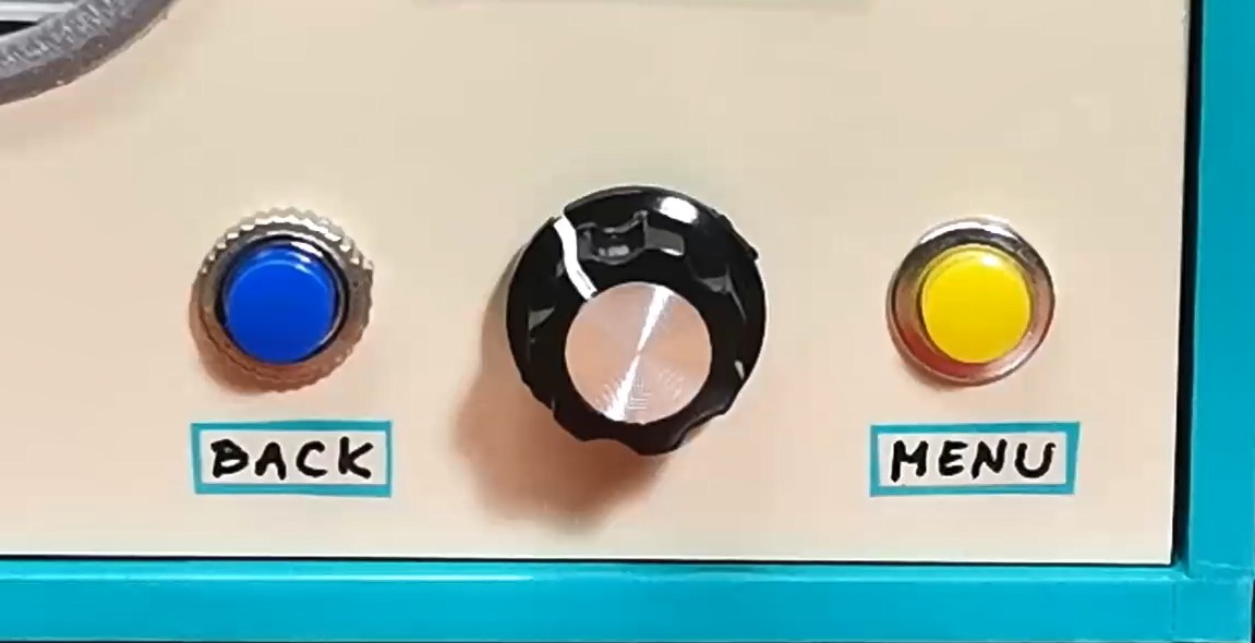
Now I will just briefly "walk" through the menu to look at all the functions and possibilities. To explain all these functions individually would take us a really long time. At the end of this text is the original manual according to which you can study all the functions in more detail. For setting the options we have two buttons MENU and BACK plus Rotary encoder with built-in button.
When turning on the receiver, the display shows the information that has been saved since the last operation.
Even at the start, on this small display it has many useful functions:
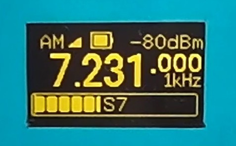
- In the middle is shown the current tuning frequency with large numbers
- Then the demodulation mode, in this case AM
- Battery status
- Signal strength in dBm
- Signal strength in the form of a bar
- as well as the tuning step
By pressing the left button we move through several interesting display modes:
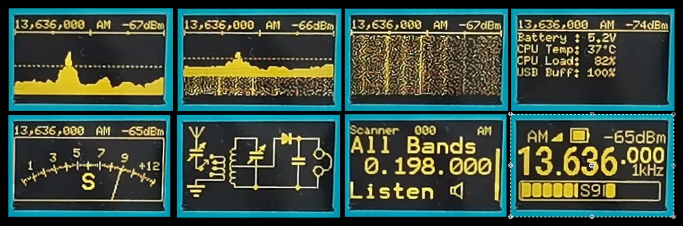
- Spectrum display
- Then spectrum plus waterfall
- then just waterfall
- data about the battery and resources of the microcontroller
- Next comes a beautiful Analog Signal Strength Meter
- Schematic of a simple detector receiver as a screensaver
- and finally we return to the home screen
With the Rotary encoder, we set the desired frequency with a tuning step that we can also adjust.
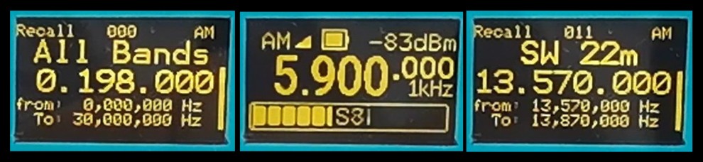
By pressing the rotary knob, we enter the menu where we can select the appropriate BAND, and by pressing it again, we activate the selected BAND.
With the right MENU button we enter the main menu where we can perform detailed settings of the received signal. With the rotary encoder we move through the menu and select the set value, and by pressing it again we confirm the selected value.
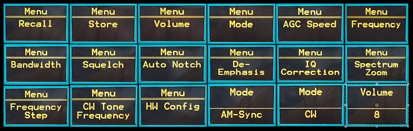
In the Menu we have the following options:
-Frequency
-Recall of stored data
- Frequency storage
- Volume value (0 to 9)
- MODE (AM, AM-Sync, LSB, USB, FM, and CW)
- AGC speed ()
- Bandwidth ()
- Squelch
- Auto NOTCH (On or OFF)
- DE-Emphasis
- IQ correction
- Band Strat and Band Sop for scan function
- Frequency setup
- CW Tone frequency
- And finally Hardware settings
We also have more additional functions and shortcuts by pressing the three buttons in combination.
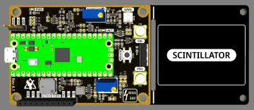
While working on the project, to my great surprise I accidentally noticed that this small SDR radio even has the option of an additional larger color display that shows the spectrum with a waterfall. The code already supports this option and we just need to add the additional display to the menu. I am currently using the case with the display mounted from a previous project of mine, but it would be even better if both displays were mounted in a larger common case.
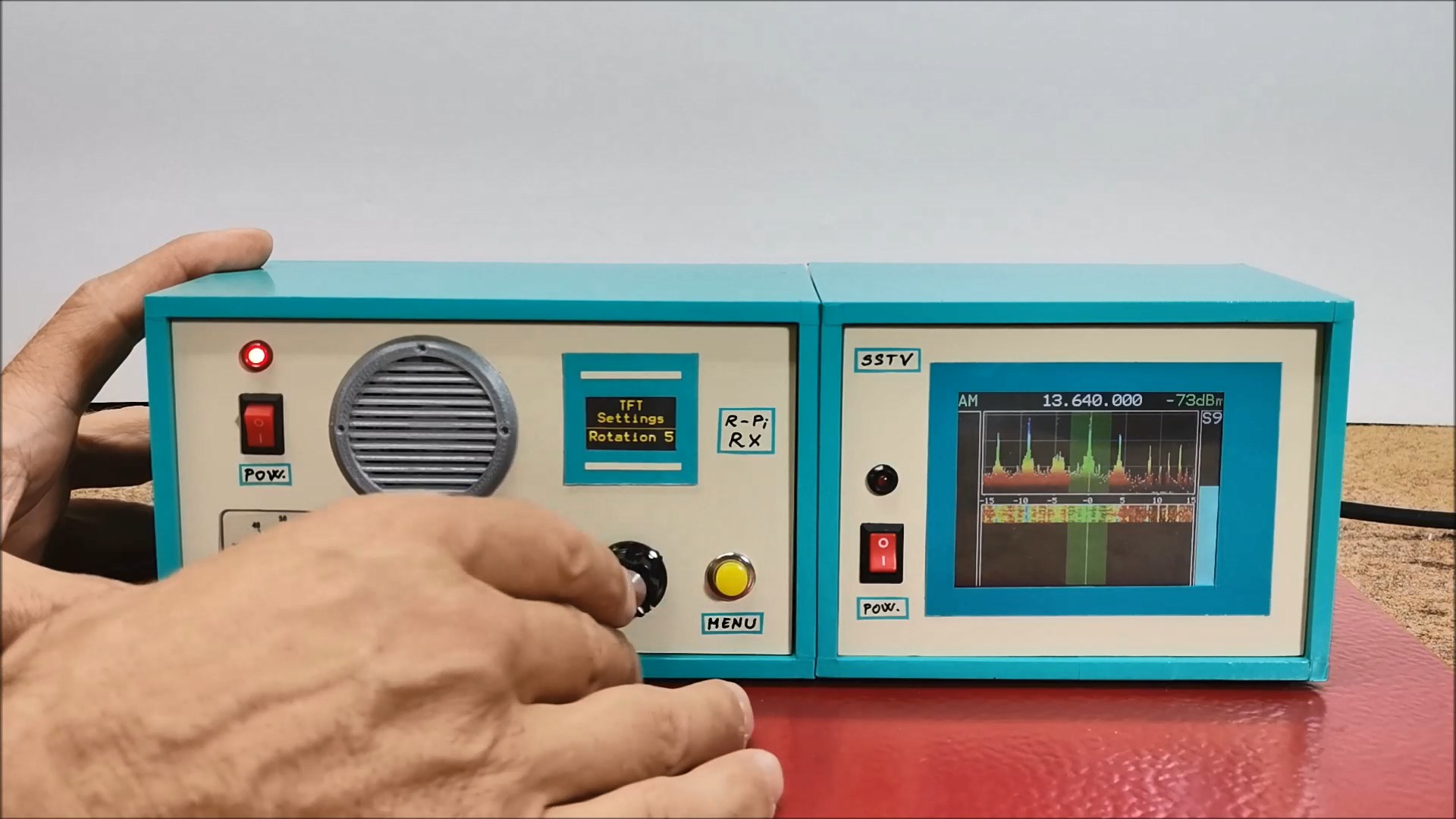
With this visual addition, this beautiful little radio becomes even more attractive. Below is the diagram for connecting the display, with a Raspberry Pi pico and I did it with a soft flat cable.
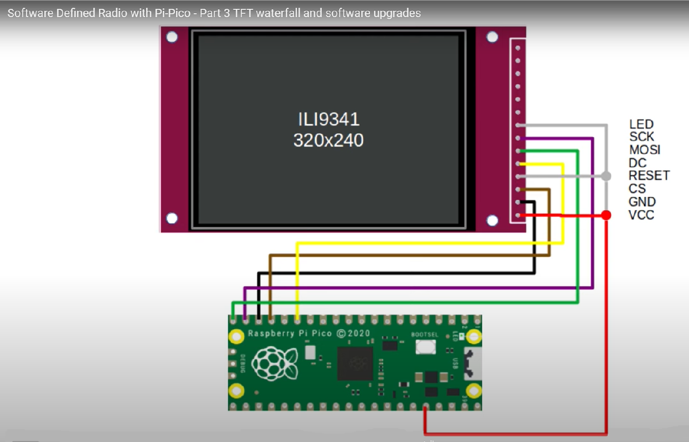
Now we need to enable second display in the Hardware menu, and set the rotation and colour.
Next I will demonstrate the reception of Broadcast stations and Amateur radio communications. As you can see, the reception is relatively poor. The reason for this is the fact that in this basic version the receiver does not contain any filter circuits at the input, and also does not have a Low Noise Amplifier that such devices usually have. Also, for the antenna I used a simple 5m wire placed on the roof of my house. In one case I used my antenna tuner and the reception was significantly better.
And finally, a short conclusion. I really have no words to describe this great project. I thank Jon Dawson for the hard work he put into it and I hope that in the future, with the support of the community, this project will develop even more. This project demonstrates the incredible potential of software-defined radio, transforming a few simple components into a powerful and flexible communication tool. I encourage you to build your own and explore the world of radio in a whole new way. It's truly remarkable to see how a simple Raspberry Pi Pico, with a bit of code, can unlock such a wide range of radio functions. I hope this video inspires you to get hands-on and join the ever-growing community of SDR enthusiasts.