
Story
The ThinkNode M1 and M2 are small LoRa transceivers that allow you to send text messages over a Meshtastic mesh network. Common applications are communication in remote areas with no Wi-Fi coverage, emergency situation when the communication infrastructure is down or IoT sensor grids.
In this tutorial I show you how to send environmental data such as temperature, humidity and pressure from a ThinkNode M2 to a ThinkNode M1 – essentially building a tiny IoT sensor grid.
What is Meshtastic?
Meshtastic is an open-source project that uses LoRa radios to form decentralized mesh networks with the aim to transport text messages. Messages are automatically relayed from one node to another, making it possible to communicate across long distance with no central infrastructure such as Wi-Fi.

Since Meshtastic is based on LoRa, a free frequency band, you don’t need a license to use it and Meshtastic devices tend to be cheap. See the Long range communication with LoRa SX1276 and ESP32 tutorial to learn more about LoRa.
The main disadvantage of LoRa is that you can only transmit small amounts of data (text messages). Also long distances can only be achieved, if the area is covered with a sufficient number of close enough Meshtastic nodes that can relay messages.
Meshtastic versus LoRaWAN
If you know LoRa you may also heard of LoRaWAN. Meshtastic and LoRaWAN are both technologies utilizing LoRa radios, but they have different architectures and purposes.
LoRaWAN is a low-power, wide-area network protocol designed for long-range, low-bandwidth communication, typically connecting devices to the internet via gateways. See our LoRaWAN with Thinknode G1 Gateway tutorial. Meshtastic, on the other hand, creates decentralized, ad-hoc mesh networks, enabling devices to communicate directly with each other without relying on infrastructure like gateways.
LoRaWAN uses a star-of-stars topology with end devices communicating through gateways to a central server. Meshtastic forms a mesh network where devices relay messages to each other, creating a decentralized and self-healing network.
LoRaWAN is suitable for large-scale IoT applications like smart cities and environmental monitoring, where devices need to transmit data to a central server. Meshtastic is better suited for off-grid communication, emergency situations, or situations where infrastructure is limited, such as in remote areas or during disasters.
What are ThinkNode M1 & M2
The ThinkNode M1 & M2 and similar Meshtastic devices are essentially like Walkie-Talkies but for text. They contain a LoRa transceiver and use the Meshtastic protocol to transport data between devices/nodes. The picture below shows the ThinkNode M1:

You will notice that the device has only a screen but no keyboard. To send messages you need to install the Meshtastic app on your mobile phone and connected it via Bluetooth to the ThinkNode. You can then type messages on your phone and get them transmitted by the ThinkNode over the LoRa/Meshtastic network to other Meshtastic devices.
Note that there are other Meshtastic devices with an integrated keyboard or touchscreen that run the Meshtastic UI on the device itself. In this case you don’t need an additional mobile phone connected to the device to send messages.
Comparison of ThinkNode M1 & M2
Meshtastic devices are based on either the nRF52 or the ESP32 as a microcontroller. nRF52-based devices consume less power and are better suited for solar-powered and handset applications. ESP32-based devices, on the other hand, offer more compute, Wi-Fi connectivity and are cheaper.
And this is also the main distinction between the ThinkNode M1 & M2. The M1 is based on the nRF52840 processor and is designed for a longer runtime due to a larger battery and an E-Ink screen. The M2 uses the more powerful ESP32-S3 as microcontroller and is generally easier to program/customize if you come from the Arduino world. The following table compares the main features of the two devices:

In the next two sections we have a quick look at the M1 and M2, individually. For a more detailed comparison see the Comparison of the M1 & M2 on the Elecrow website.
ThinkNode M1
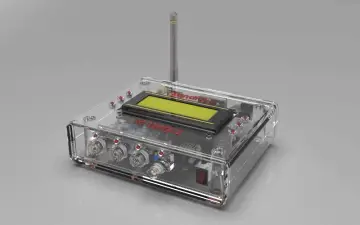
As mentioned above, the ThinkNode M1 uses the nRF52840 as the main processor. It has a SX1262 chip for LoRa communication, a 1200mAh rechargeable battery, a 1.54-inch EPD display with backlight, a small buzzer and a built-in GPS module. The picture below shows the device:

Charging is via a Type-C USB port and the device can be configured with the Meshtastic App, which communicates with the device via Bluetooth. The App also enables map and location sharing, network status monitoring, data exporting and more. For more information have a look at the Radio Configuration Website.
All the technical details of the ThinkNode M1 can be found in the ThinkNode M1 Datasheet and for general usage information see the ThinkNode M1 Manual.
ThinkNode M2
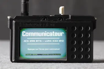
The ThinkNode M2 uses the ESP32-S3 as the main processor, which is more powerful than the nRF52840. Due to the processor and the smaller 1000mAH the runtime is shorter, however. Furthermore, the M2 uses a 1.3-inch OLED display, which also consumes more power. The photo below shows the ThinkNode M2:

Note that the M2 lacks the GPS module of the M1 but runs the same software and is also configured with the Meshtastic App.
All the technical details of the ThinkNode M2 can be found in the ThinkNode M2 Datasheet and for general usage information see the ThinkNode M2 Manual.
Connecting Sensors to a Meshtastic Node
The Meshtastic firmware supports simple, so called Detection Sensors connected to specified GPIO pins or a selection of more complex sensors that are connected via I2C and configured in the Telemetry Module. This selection of sensors includes the BM680 environmental sensor, I want to use in this tutorial.
Unfortunately, while the ThinkNode M2 module exposes some GPIO pins it does not expose the pins for I2C – at least as far as I could see. According to the Datasheet those should be IO15_SCL and IO16_SDA but they don’t appear in the table of available GPIO pins:

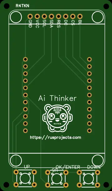
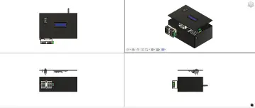
Note that GPIO pins are not accessible from the outside. You have to either open the case of the ThinkNode M2 or get the plain module (without the case). The picture below shows the front and back of the bare ThinkNode M2 module:

So how to connect a BM680 environmental sensor to a ThinkNode M2? We could modify the Meshtastic firmware to either configure additional/other I2C pins but that would not be easy.
Alternatively, if we could program the ESP32-lite to send messages using the Meshtastic protocol, we then would not need the ThinkNode M2. But I have not found a library that allows me to do this.
That leaves us with the third option, which seems to be the common way to deal with this problem. We configure the ThinkNode M2 to forward text messages sent via the serial interface (UART).
This means, however, that we need an additional microcontroller, here an ESP32-lite. The ESP32-lite is connected to BME680 to process its data and sends it as a text message over the serial interface to the ThinkNode M2. This is the method we are going to use to build a simple IoT grid as described in the next section.
Building an IoT grid with ThinkNodes
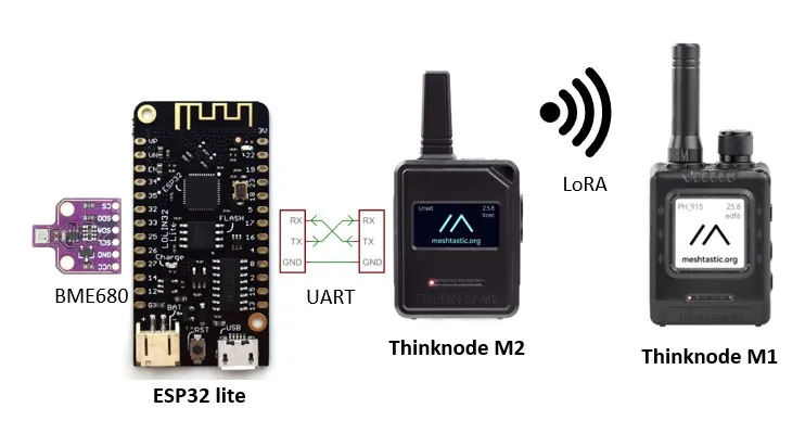
Our tiny IoT sensor grid is composed of an ESP32-lite with an attached BME680 sensor, a ThinkNode M2, which sends environmental data and a ThinkNode M1, which receives and displays the data. The following picture shows the architecture of the system:

The BM680 sensor connected to an ESP32-lite measures temperature, humidity and pressure. The ESP32-lite communicates with a ThinkNode M2 device via the serial interface (UART).
Environmental data from the BM680 ares sent as text messages from the ESP32-lite to the ThinkNode M2. The ThinkNode M2 then sends this data wirelessly via LoRa to the ThinkNode M1, which displays it on its screen.
Connecting ESP32-lite with ThinkNode M2 via UART
I have the ThinkNode M2 with the case and while it is easy to open the case (just remove the four screws at the back) the actual circuit board seems to be glued in. I was not able to remove the module without risk breaking it.
Which means, I could not solder a pin header to the GPIO holes on the board as planned. Instead I connected wires with clips to IO18, IO19 and GND as show in the photo below:

These wires, I then connected to the ESP32-lite as shown in the wiring diagram below:

IO17 of the ESP32 is connected to IO18 of the M2, and IO16 of the ESP32 is connected to IO19 of the M2. With this wiring we can establish a serial communication (UART) between the ESP32-lite and the ThinkNode M2.
Connecting ESP32-lite with BME680 to ThinkNode M2
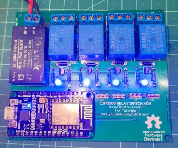
Next, we need to connect the BME680 to the ESP32-lite. The picture below shows the complete wiring of the BME680 with the ESP32-lite and the ThinkNode M2:

The BME680 supports I2C and is therefore connected to the default I2C pins (SDA=19, SCL=23) of the ESP32-lite. We also need to connect the power supply (3.3V and ground). If you need more information on the BME680 have a look at the BME680 Environmental Sensor with Arduino, the Measure Air Quality with BME680 and the Send Environmental Data with LoRa tutorials.
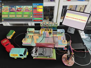
The following photo shows the complete wiring on a breadboard including the ThinkNode M2 and ThinkNode M1:

Configuring ThinkNode M1 and M2
Before we can send any data between the two ThinkNodes we need to configure them. Specifically, we need to set the LoRa frequency and ensure that it is the same for both nodes.
To configure a ThinkNode, open the Meshtastic App on your mobile phone, connect it via Bluetooth to the the ThinkNode (you will get a code) and then click on the three dots in the upper left corner to open the menu. See the Wiki for the ThinkNode M1 and the Wiki for the ThinkNode M2, if you need more detailed information.
Configuring the LoRa Frequency
In the menu select “Radio configuration” and then “LoRa”, which will open the “LoRa Config” page:

There you can set the Region with an associated frequency. You must select your region/country and you must do the same for both ThinkNodes M1 and M2, otherwise they cannot communicate!
Note that the permitted LoRa frequencies depend on the country. It is 868MHz for Europe, 915MHz for North America and 433MHz for Asia. Since, I live in Europe, I selected “European Union 868MHz” as region/frequency in the screenshot above.
If you have problems with the configuration there are many tutorials to help with the setup. For instance, see the ThinkNode M1/M2 Review – Getting started with Meshtastic tutorial. Or the Meshtastic Configuration info.
Once configured, you should verify that you can send text messages from the ThinkNode M2 to the ThinkNode M1. If that works we can then configure the serial interface of the ThinkNode M2.
Configuring the Serial Interface
We want to connect the ESP32-lite via the serial interface to the ThinkNode M2. This requires additional configuration of the ThinkNode M2.
Open the menu by clicking on the three dots (as before). Select “Radio Configuration” and then “Serial”. This will open the “Serial Config” page as shown below:

Switch on “Serial enabled” and set the GPIO pins for serial communication (RX and TX). I picked RX=18 and TX=19. Set the baud rate to 115200 and the mode to “TEXTMSG”. This mode tells the ThinkNode to forward/transmit any text it receives via the serial interface.
And with that we are finally ready to write some code that allows us to transmit some data.
Send Data via ThinkNode M2 to M1
We start with a simple test code that creates a running counter on the ESP32-lite, which is sent via serial communication to the ThinkNode M2, which then transmits it via LoRa to the ThinkNode M1. Below is the code for the ESP32-lite:
#define TX_PIN 17  // ESP32 TX -> M2 RX 18
#define RX_PIN 16  // ESP32 RX <- M2 TX 19

#define BAUD_RATE 115200
#define SEND_PERIOD (60 * 1000)

HardwareSerial serial2(2);

void setup() {
  Serial.begin(115200);
  serial2.begin(BAUD_RATE, SERIAL_8N1, RX_PIN, TX_PIN);
}

void loop() {
  static int cnt = 0;
  static char msg[128];

  sprintf(msg, "counter=%d", cnt++);
  serial2.println(msg);  // Sending to ThinkNode M2
  Serial.println(msg);
  delay(SEND_PERIOD);
}
Upload this code to the ESP32-lite, switch on the ThinkNode M1 and M2 and you should receive every minute a text message “counter=…” on the ThinkNode M1.
Let’s have a closer a the code. We start by defining the pins for the serial interface and constants for the boud rate and the time between transmission (60 seconds):
#define TX_PIN 17  // ESP32 TX -> M2 RX 18
#define RX_PIN 16  // ESP32 RX <- M2 TX 19

#define BAUD_RATE 115200
#define SEND_PERIOD (60 * 1000)
You should pick pins for serial communication that are supported by your microcontroller. In case of the ESP32-lite there are three serial hardware interfaces (0,1,2) and I am using the third one:
HardwareSerial serial2(2);In the setup function we start the serial communication to the Serial Monitor for debugging and the serial communication to the ThinkNode M2, with the defined pins and baud rate:
void setup() {
  Serial.begin(115200);
  serial2.begin(BAUD_RATE, SERIAL_8N1, RX_PIN, TX_PIN);
}
As for the loop function: There we increment a counter, create a text message with the counter value, print it to the Serial Monitor and also send it via the serial interface to the ThinkNode M2. The delay at the end ensures that this happens every minute:
void loop() {
static int cnt = 0;
static char msg[128];
sprintf(msg, "counter=%d", cnt++);
serial2.println(msg); // Sending to M2
Serial.println(msg);
delay(SEND_PERIOD);
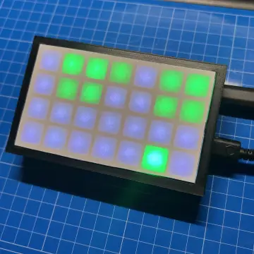
}On the display of the ThinkNode M1 you should then see the counter:

Note that you may have to press the Function button to get the display to update. If this works we can proceed to send some real data.
Code to send Environmental Data
The following code reads environmental data such as temperature, humidity and pressure from the BME680 sensor and sends them to the ThinkNode M2, which in turn forwards them to the ThinkNode M1:
#include "Adafruit_BME680.h"

#define SEALEVELPRESSURE_HPA (1013.25)

#define TX_PIN 17  // ESP32 TX -> M2 RX 18
#define RX_PIN 16  // ESP32 RX <- M2 TX 19

#define BAUD_RATE 115200
#define SEND_PERIOD (60 * 1000)

HardwareSerial serial2(2);
Adafruit_BME680 bme;

void setup() {
  Serial.begin(115200);
  serial2.begin(BAUD_RATE, SERIAL_8N1, RX_PIN, TX_PIN);

  bme.begin();
  bme.setTemperatureOversampling(BME680_OS_8X);
  bme.setHumidityOversampling(BME680_OS_2X);
  bme.setPressureOversampling(BME680_OS_4X);
  bme.setIIRFilterSize(BME680_FILTER_SIZE_3);
  bme.setGasHeater(320, 150);  // 320*C for 150 ms
}

void loop() {
  static char msg[128];

  if (bme.performReading()) {
    sprintf(msg, "temperature: %.0f C\nhumidity: %.1f %%\npressure: %.0f hPa\n",
    bme.temperature, bme.humidity, bme.pressure/100.0);

    serial2.println(msg);  // Sending to ThinkNode M2
    Serial.println(msg);

    delay(SEND_PERIOD);
  }
}
The code is a simple extension of the previous code. We just add the initialization of the BME680 to the setup function:
void setup() {
  ...

  bme.begin();
  bme.setTemperatureOversampling(BME680_OS_8X);
  bme.setHumidityOversampling(BME680_OS_2X);
  bme.setPressureOversampling(BME680_OS_4X);
  bme.setIIRFilterSize(BME680_FILTER_SIZE_3);
  bme.setGasHeater(320, 150);  // 320*C for 150 ms
}
and create the text message from the BME680 measurements in the loop function when measurements are available:
void loop() {
  ...
  if (bme.performReading()) {
    sprintf(msg, "temperature: %.0f C\nhumidity: %.1f %%\npressure: %.0f hPa\n",
    bme.temperature, bme.humidity, bme.pressure/100.0);

    serial2.println(msg);  // Sending to ThinkNode M2
    ...
  }
}
Note that you will need to have the Adafruit BME680 library installed. It provides all the essential functions to control the BME680 sensor.

If you want to learn more about the BME680 and the corresponding code see the BME680 Environmental Sensor with Arduino, the Measure Air Quality with BME680 and the Send Environmental Data with LoRa tutorials.
On the display of the ThinkNode M1 you should now receive the following environmental data:

And that’s it. You now have a tiny Meshtastic IoT sensor grid with an BME680 sensor and the M1 and M2 ThinkNodes as Meshtastic nodes. You could easily extend the range and function of this network by adding more Meshtastic nodes or sensors.
Conclusions and Comments
In this article you learned how to build a small IoT sensor grid with an BME680 sensor and the M1 and M2 Meshtastic ThinkNodes.
The Meshtastic mesh allows you to send sensor data over longer distances than LoRa alone and does not require Wi-Fi or similar communication structure. However, it requires other Meshtastic nodes in the vicinity that can pass on data. As of July 2025 the number of Meshtastic nodes in most areas is not high enough to provide full coverage. See the Meshmap.
Between the M1 and M2, I reached a distance of maybe 200 to 300 meters before the devices lost connection. For a detailed range test and comparison read the ThinkNode M1/M2 Review – Getting started with Meshtastic post by Jean-Luc Aufranc.
If you want to transmit sensor data over a few hundred meter you are better of just using raw LoRa. It will be simpler and will give you more flexibility. See the Send Environmental Data with LoRa tutorial on how to do this.
For a larger range or setups with many sensors that need to send measurements to the internet LoRaWAN is another option. See the LoRaWAN with Thinknode G1 Gateway tutorial for more information on this topic.
Despite its current limitation and comparatively small coverage, Meshtastic is a fun technology to play and the community is growing. I strongly suggest you read more About Meshtastic.
Happy Tinkering ; )