Story
As a software engineer, hardware is always difficult for me. But as my boss need me learn more about the hardware, or he would fire me and kick me off, I have to learn more, with the very basic knowledge about these sensors, shields, controllers and so on. I will sort them out, to share with more friends.
Here I would sort out how to use a relay and something about the Elecrow Relay Shield. Hope it helps for some beginners.
Step 1: Why We Use a Relay?
As we know, if we connect a LED to the digital output of Arduino, and make this pin output High or Low, the LED would be on/off. This is the first step to learn Arduino. But sometimes, we want to control some modules that works in high voltage/large current, for example, I want to control my lamp (works in voltage>100V) with the Arduino, it is not a good idea to connect the lamp to the Arduino digital output pin now.
Yes, the Arduino can only output voltage 5V max, and current 20mA max. It is much lower that the voltage that the lamp works with. We need a module to make it possible to control the high voltage/large current with Arduino.
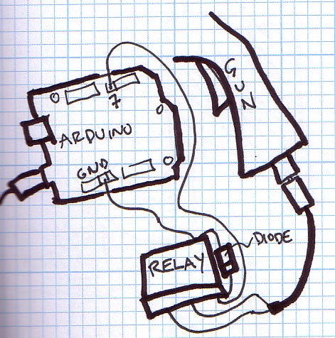
That is what a relay can do. The relay is an electrically operated switch, it acts like a soldier, accept low voltage signal commands for Arduino, and then control the high voltage gun on/off.
Step 2: How to Use a Relay?
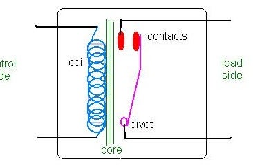
There are so many kinds of relays on the market, but the most basic Relay has at least 2 parts: commander(control size) and action part(load side) .
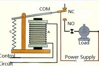
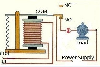
As a soldier that strictly carry out commands from the commander, the relay receive the commands and then acts like a switch: when the commander says:” connect!”, it connects the “pivot” pin to the left side of red contacts, so that the right parts of the circuit connected; when the commander says: “do not connect!”, it connect the pivot with the right side of the red contacts, so the right parts of the circuit disconnected.
A typical relay that are most often used on the market as above photo:
Normally there are 3 ports in the relay: COM port, NC(Normally connected to COM) port, and NO(Normally Open to COM)port. When the control circuit not powered, the “COM” port contacts the “NC” port as there is a Spring ”C” pulls it; when the control circuit powered, the coil “A” will generate electromagnetic attraction to make the “COM” port contacts the “NO” port, thus make the left circuit connected. And if there is enough power supply , the DC motor would begin to run.
Step 3: How Elecrow Design the Relay Shield?
Yes, it is so easy to use a relay. But it is theoretical, we need to notice something in actual usage. The Elecrow Relay Shield has the following points to ensure its usage.
1. Reliable Relays and layout.
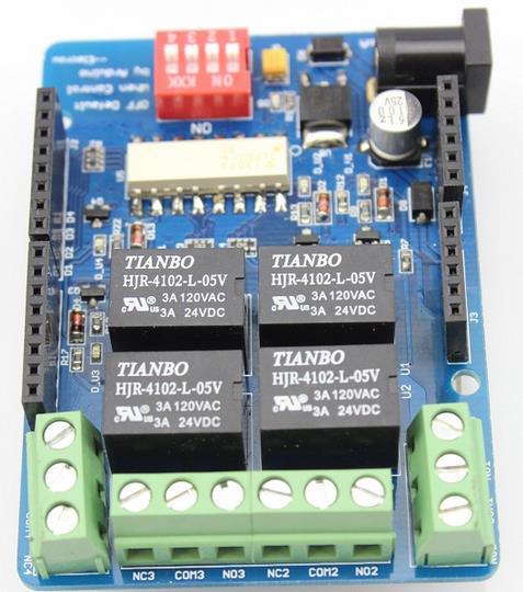
A reliable relays is the most important, and as the copper width and weight will Impacts the max current that can be flowed in the circuit, the width of the layout should meet the current requirements. The Elecrow use reliable relays that supports current 3A@120VAC and 3A@24VDC, with 100 mils layout. Besides,
the high voltage area are not copper planted, to avid the high voltage affects the GND.
2. Isolation within HIHG voltage and Low voltage circuit;
The HIGH voltage is dangerous,both for human beings and the controller. If there is any problem, the HIHG voltage may destroy all the circuit, especially the microcontroller. So, isolation between the HIHG voltage circuit(active side) and LOW voltage circuit(commander side) is essential.
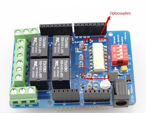
The elecrow uses a optocouplers TLP521 IC to isolate them. With this optocoupler, risk of controller damaged by the high voltage would reduce, as the high voltage would not pass the optocoupler.
3.How to drive the commander?
The coil “A” would need current to make enough strength to attract the COM port, but as the Arduino digital can only output 20mA current , we also need a drive circuit to drive the relay, using a transistor:
When DOUT3 gets HIIGH voltage(5V), the emitter and colletor of transistor
(Q3)would be conductive, thus the current would flow from +5V power supply, to R17, and then the relay, and then the Q3, and GND. The R17 is selected to limit the current, to make it suitable for the relay.
You can also see a diode D14 parallel to the relay, to limit the Back-EMF to protect the relay, also, a LED serial to a current-limit resistor to show users the working state.
4.Power for the Relay, and Arduino board.
When the onboard 4 relays are all active, they need a max current of about 300mA, that is a large load for Arduino power circuit, especially when powered by USB( 500mA max). So, an extra power circuit is added in the elecrow relay shield, with a diode (D6) to protect the board when power reversed connected.
5. Manual Control.
I believe there is also sometimes you just want to control the HIHG voltage manually. For example, if you made an auto-off lamp that turn out after 11 o’clock, but sometimes you do need it on because you need to write a email to your girlfriends.
That is why we add the manual control for the relay shield. With the switch on the board in “OFF” state, the relay will be always be on its default state, that is , the COM port connect the NC port, but not controlled by the Arduino.
Step 4: How to Use the Elecrow Relay Shield?
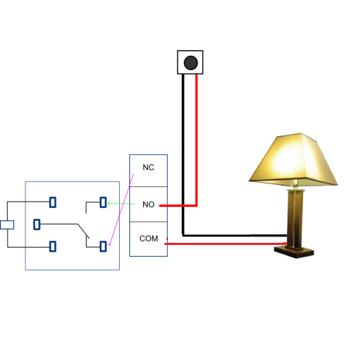
With the above the hardware, it would be easy to use the elecrow now. for example, we want to use the relay shield to control the lamp on/off, connect the relays as below:
1. Cut off the power wire of your lamp;
2. Connect on end to the COM1, and the other end to NO1;
3. Ensure the manual control switch on the off side;
4. Insert the relay shield on Arduino and power up.
Now, you can control the lamp on/off by Arduino, digital out HIHG on D5 would makes the COM port connected with the NO1, that is , the lamp will be on; while output a logical LOW while makes the lamp off.
More applications: you can also refer to this: https://www.instructables.com/id/Control-the-relays-via-GPRS-SMS/ for more usage of relay shield.


