







Story
Displays play an important role in embedded and IoT projects by providing real-time visual feedback. Whether you are monitoring sensor values, building a compact user interface, or displaying system status, a small OLED display can significantly improve the usability of your project.
Compared to conventional LCD modules, OLED displays provide sharper contrast, lower power consumption, and much better viewing angles. Since each pixel emits its own light, there is no need for a backlight, making OLED modules thinner and more efficient for portable applications.
In this project, we will interface a 0.96-inch SSD1306 OLED display with Arduino using both I2C and SPI communication methods. You will learn the module pinout, working principle, and hardware setup required to quickly integrate OLED displays into your own electronics projects.
Why Use OLED Displays?
OLED displays are widely used in:
- IoT dashboards
- Smart home devices
- Portable electronics
- Wearable projects
- Sensor monitoring systems
- DIY embedded interfaces
Key advantages include:
- Excellent contrast and readability
- Low power consumption
- Compact size
- Wide viewing angles
- Pixel-level graphics control
Unlike character LCDs, OLED modules allow you to display text, graphics, icons, and even simple animations.
Components Required
- Arduino Nano
- SSD1306 OLED Display Module (128×64)
- Jumper wires
- Breadboard (optional)
- USB cable for Arduino programming
- 5V power supply
OLED Module Overview
The OLED module used in this project is based on the SSD1306 display controller. This controller handles communication between the Arduino and the OLED panel while internally storing pixel information inside display memory.
The module is available in two common communication variants:
- I2C OLED → Simple wiring using only two communication lines
- SPI OLED → Faster communication for graphics-intensive applications
Most SSD1306 modules support operation from 3.3V to 5V, making them compatible with Arduino boards without additional level shifting.
I2C OLED Pinout
The I2C version is the most beginner-friendly because it requires only four connections.
Pins Description
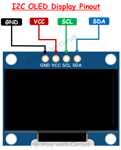
- GND → Ground connection
- VCC → Power supply input
- SCL → Serial clock line for I2C communication
- SDA → Serial data line for I2C communication
The default I2C address for most SSD1306 OLED modules is usually 0x3C.
SPI OLED Pinout
SPI OLED modules use additional control lines for faster data transfer.
Pins Description
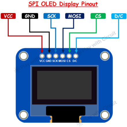
- GND → Ground
- VCC → Power supply
- SCK → SPI clock signal
- MOSI → Data input line
- CS → Chip select pin
- DC → Data/command control pin
SPI communication is ideal when frequent screen updates or animations are required.
Working Principle
The SSD1306 controller contains internal display memory called GDDRAM (Graphic Display Data RAM). Instead of directly controlling each pixel continuously from the Arduino, the microcontroller sends graphical data to this memory buffer.
The controller then refreshes the display automatically using the stored data. This reduces processing overhead and enables smooth rendering of text and graphics.
The display memory is organized into pages and columns, where each bit corresponds to a single OLED pixel.
Hardware Connections
I2C OLED Wiring
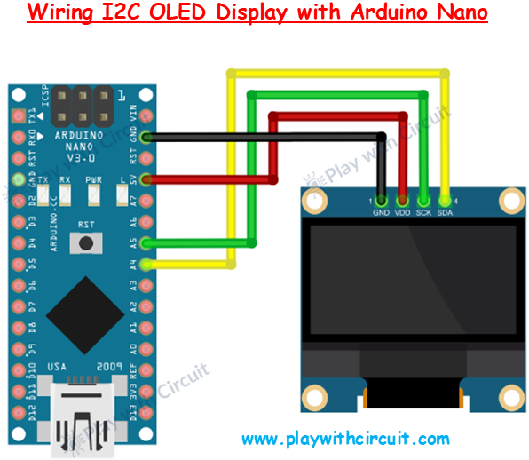
Connect the OLED module to Arduino as follows:
- OLED VCC → Arduino 5V
- OLED GND → Arduino GND
- OLED SCK → Arduino A5
- OLED SDA → Arduino A4
This method is recommended for most beginners because it uses fewer wires and simplifies circuit design.
SPI OLED Wiring
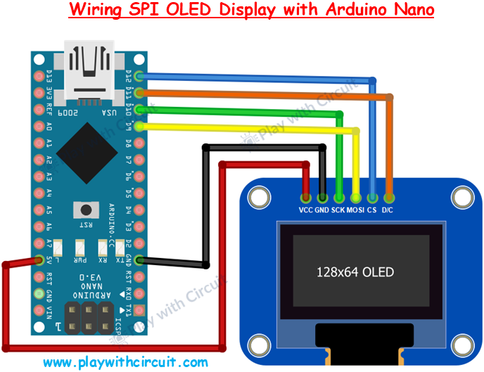
For SPI communication:
- OLED VCC → Arduino 5V
- OLED GND → Arduino GND
- OLED SCK → Arduino D10
- OLED MOSI → Arduino D9
- OLED CS → Arduino D12
- OLED DC → Arduino D11
SPI provides faster communication speed compared to I2C and is useful for graphics-heavy projects.
Libraries Required
To interface the OLED display easily, install these libraries from the Arduino IDE Library Manager:
- Adafruit SSD1306
- Adafruit GFX
These libraries provide ready-to-use functions for displaying text, shapes, and bitmap images.
Drawing Shapes on OLED Display
Development Tips
- Keep communication wires short to avoid noise issues
- Use an I2C scanner sketch if the display is not detected
- Verify OLED voltage compatibility before powering
- SPI is better for faster graphical updates
- Use custom PCBs for cleaner and more reliable integration
Applications
Once integrated, OLED displays can be used in:
- Weather monitoring systems
- Smart clocks
- IoT control panels
- Battery-powered devices
- Sensor visualization systems
- Mini embedded user interfaces
Conclusion
OLED displays are one of the most useful additions to modern Arduino and embedded projects. Their compact size, excellent visual quality, and low power requirements make them ideal for both beginner and advanced applications.
Whether you choose I2C for simplicity or SPI for speed, SSD1306 OLED modules offer a flexible and efficient solution for displaying information in real time.
For complete implementation details, Arduino code, and step-by-step instructions, check the original tutorial here:
👉 https://playwithcircuit.com/interfacing-oled-display-with-arduino/