
Story
DIY Compact Wi-Fi Deauther (ESP-01 + OLED)
⚠️ Disclaimer:
This project is for educational and testing purposes only. A Wi-Fi deauther exploits how Wi-Fi works and can disrupt connections. Use it only on your own network and devices. Laws vary depending on where you live, so make sure you understand what’s legal before continuing.
Step 1 – Why Use the ESP-01?
Most people use boards like the NodeMCU ESP8266 for Wi-Fi projects because they’re easy to program and have many pins. But the ESP-01 is an underrated little module that is:
-
Tiny (it becomes almost keychain-sized once inside a 3D-printed case)
-
Cheaper than most ESP8266 development boards
-
Based on the same ESP8266 chip, so it is fully capable
With careful wiring, you can connect it to an OLED display, navigation buttons, and a battery. Despite the ESP-01’s limited pins, this setup makes for a very compact and portable Wi-Fi deauther.
Step 2 – Parts You’ll Need
Here is the full list of components:
-
ESP-01 Wi-Fi module
-
0.96" OLED display (I²C interface)
-
2 push buttons (for navigation and selection)
-
Rechargeable Li-ion or LiPo battery
-
Charging module (like TP4056)
-
Tiny slide switch for power control
-
Wires and soldering tools
-
Optional: Arduino Uno (if you don’t have an ESP-01 USB programmer)
-
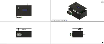
3D-printed case to house the circuit
These parts are inexpensive and many makers already have some lying around.
Step 3 – Programming the ESP-01
-
Get an ESP-01 programmer adapter for easy flashing.
-
If you don’t have one, you can use an Arduino Uno as a programmer (tutorial: https://www.youtube.com/watch?v=3J1Ys7q8DTg).
-
-
Download the ESP8266 Flasher tool from:
https://github.com/JhonControl/ESP8266-Flasher -
Download the modified deauther firmware that works with ESP-01 and OLED:
-
Open the Flasher tool → Config tab → select the correct
.binfile. -
Place the ESP-01 in programming mode by connecting GPIO0 → GND before flashing.
-
Click Flash and wait for the firmware to upload.
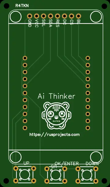
Step 4 – Initial Wiring (with headers)
Before making things compact, keep the ESP-01 header pins attached. Wire like this:
-
3V3 → OLED VCC -
GND → OLED GND -
IO0 → OLED SCL -
IO2 → OLED SDA -
TX → Button SELECT -
RX → Button OK
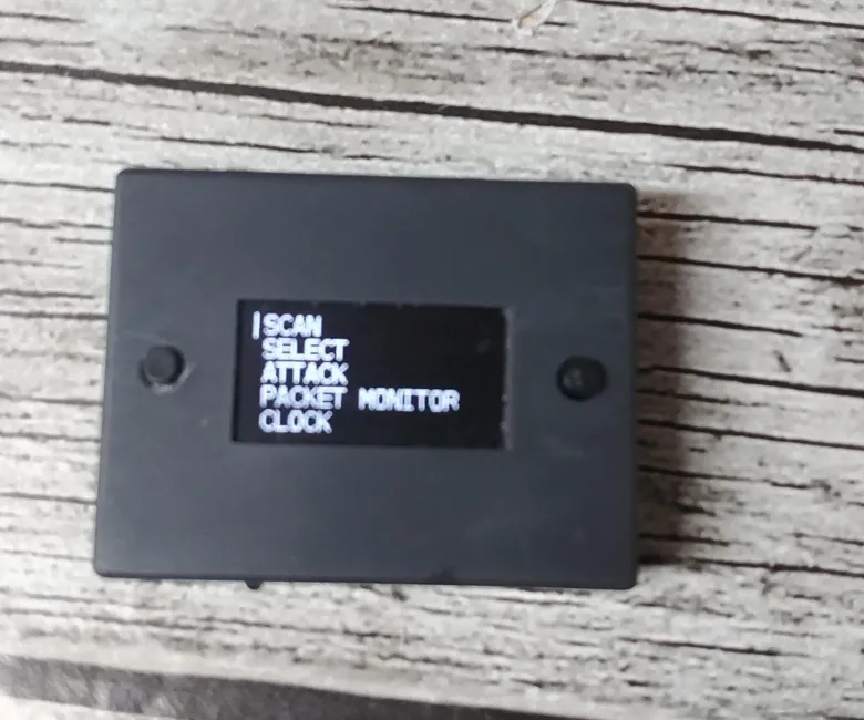
Once powered, you should see the deauther interface on the OLED screen.
Step 5 – Compact Wiring (without headers)
After confirming everything works, carefully desolder the ESP-01 headers. Then solder components directly to reduce space:
-
3V3 → OLED VCC -
GND → OLED GND -
IO0 → OLED SCL -
IO2 → OLED SDA -
TX → Button SELECT -
RX → Button OK -
GND → Battery GND -
Battery 3V → Charging Module VCC -
3V3 → VCC -
GND → Charging Module GND -
Switch Pin 1 → GND -
Switch Pin 2 → Charging Module GND
This setup makes the whole build smaller and cleaner.
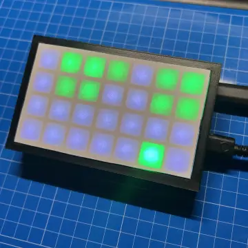
Step 6 – Final Assembly
-
Insert all the components into your 3D-printed case.
-
Secure the OLED so the screen is visible.
-
Place the push buttons where they can be easily pressed.
-
Install the slide switch for power control.
-
Connect and secure the battery.
The end result is a neat, compact, and fully functional device.
Step 7 – Enjoy Your Build
Once assembled, power it on and navigate the on-screen menu using the buttons. The ESP-01 deauther will now be operational.
It’s a fun project that shows how much you can achieve with minimal hardware. Just remember: use it responsibly, and only on your own devices and network.