


Story

In this article we will examine how to use and how Reyax LoRa modules behave, focusing in particular on the RYLR998. I developed a library that enables bidirectional communication, including message reception acknowledgment. The entire firmware was written using the Arduino IDE, both to speed up development and to make the code easily accessible and reusable by anyone.
What is LoRa technology?
LoRa, short for Long Range, is a radio-frequency wireless communication technology specifically designed for Internet of Things (IoT) applications and LPWAN (Low Power Wide Area Network) infrastructures.
Unlike technologies such as Wi-Fi or Bluetooth, which are intended to transmit large amounts of data over relatively short distances, LoRa was designed with the opposite goal: sending small data packets over very long distances while consuming very little power.
The key strength of LoRa technology lies in its use of a modulation technique called Chirp Spread Spectrum (CSS). This approach makes the signal highly resistant to interference and noise, allowing communication over several kilometers even in the presence of physical obstacles or dense urban environments.
RYLR998's specs

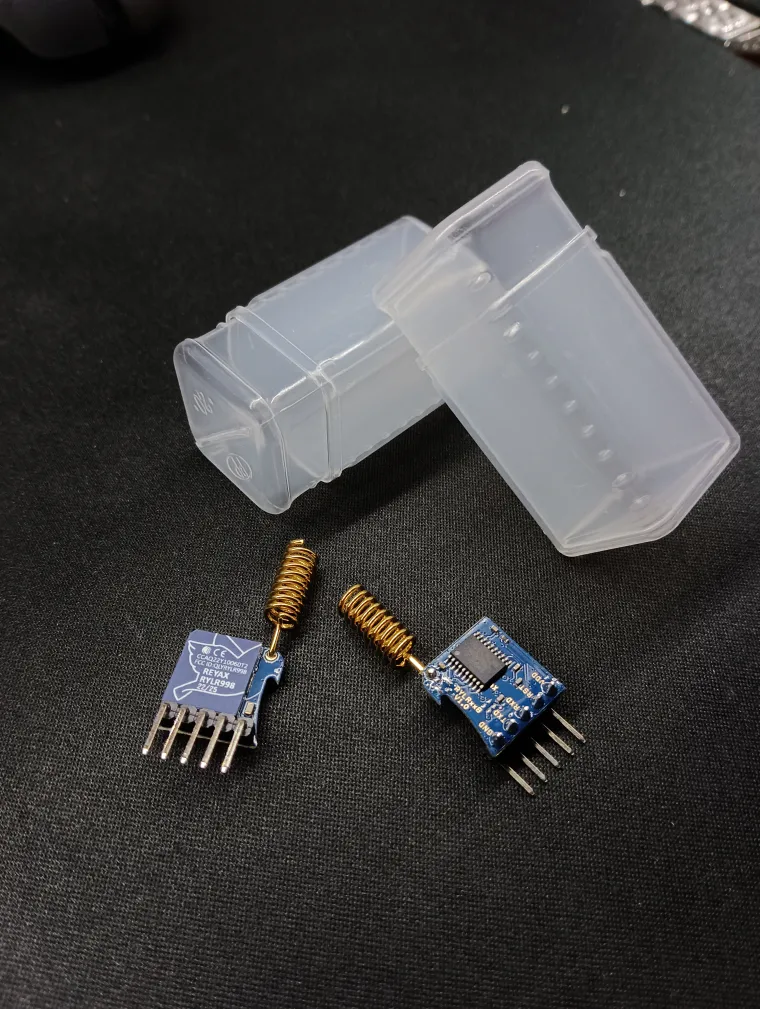
These modules are LoRa transceivers, meaning they are capable of both transmitting and receiving data. They can therefore be used to send small amounts of information over long distances, making them particularly suitable for applications such as autonomous sensors powered by energy harvesting, for example using solar energy.
Below are some of the main technical features:
- Integration of an internal microcontroller to manage communication via AT commands;
- Built-in antenna capable of providing a communication range of several kilometers;
- Implementation of a Smart Receiving Power Saving Mode to further reduce power consumption;
- Support for data encryption.
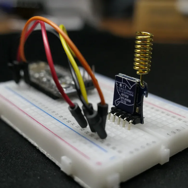
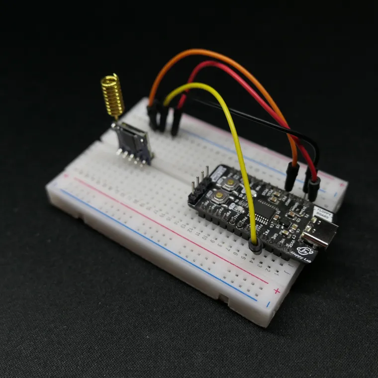
The modules operate with a 3.3 V power supply, which makes the Floppy Board 3 an ideal candidate for controlling the system. Since they are managed through AT commands, the required hardware interface is minimal: a 3.3 V power supply (with at least 150 mA available) and a UART serial interface using TX and RX lines are sufficient.
Regarding radio performance, the datasheet specifies a maximum transmit power of 22 dBm, corresponding to approximately 158 mW. However, in order to comply with CE certification, it is explicitly recommended to limit the output power to 14 dBm, which is about 25 mW. The module allows the transmission of data packets up to 240 bytes per transmission. On the receiving side, in addition to the received data, it is also possible to retrieve signal quality metrics such as RSSI (Received Signal Strength Indicator) and SNR (Signal-to-Noise Ratio).
Range test
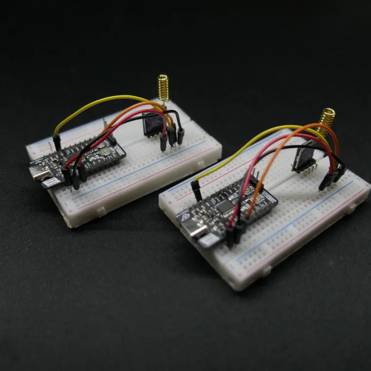
The transmission distance test was carried out using the default module settings, without applying any configuration changes and relying solely on the built-in antenna supplied with the module.
Two identical modules were used, each mounted on a separate breadboard and controlled by two Floppy Board 3 boards.
The code used for the test is intentionally very simple. Thanks to the library I developed, it is only necessary to initialize the system and use the data transmission and reception functions. All the Arduino IDE project files are available at the end of the article for anyone interested in replicating the experiment.
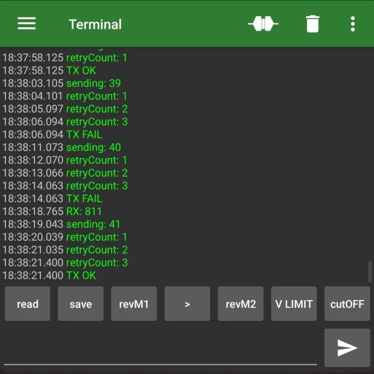
The firmware used for this test simply sends an incrementing numeric value every three seconds, while continuously listening for incoming packets from the second circuit. By powering on the two devices with a time offset of about 1.5 seconds, it is ensured that when one module is transmitting, the other is certainly in reception mode.
The library also implements a reception acknowledgment mechanism: the receiving module sends a confirmation message back to the transmitter, allowing verification that the packet has been correctly received. If no acknowledgment is received within a predefined time, the packet is retransmitted up to two additional times, for a total of three transmission attempts.
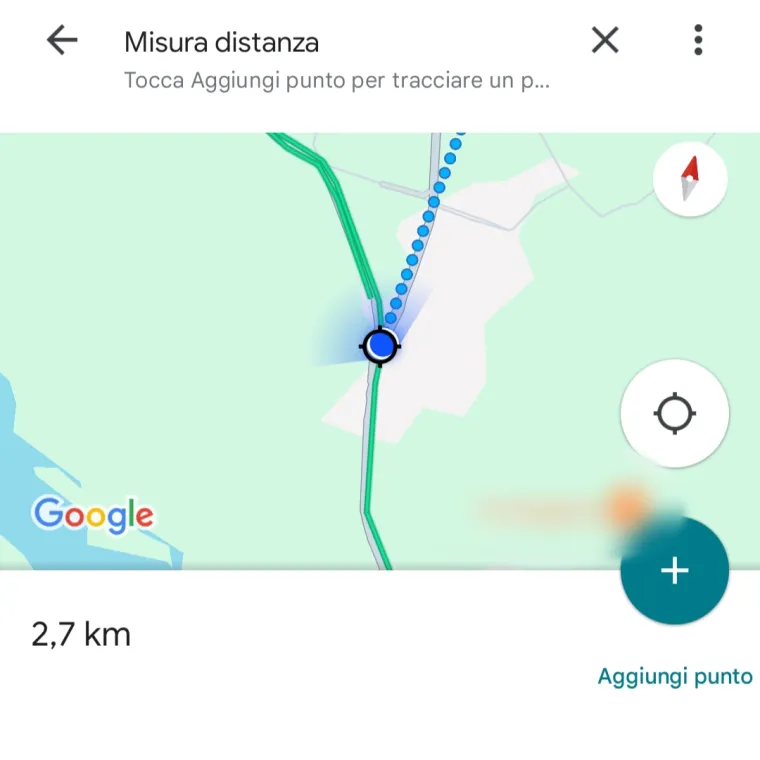
For the practical test, I placed one circuit outside the front door of my house, while the other was connected to a smartphone, both to power it and to monitor the received data. At this point, the field test began.
I consider this test to be fairly representative of real-world scenarios involving sensors deployed in different environments. The path I followed was quite varied, including both clear line-of-sight sections and fully urban areas, with buildings and hills located between the transmitter and the receiver.
When a hill and several buildings were present between the two circuits, the signal struggled to overcome the obstacles and reach the receiver I was carrying. However, when the attenuation was caused only by a large number of buildings, at a distance of about 1 km in line of sight, no significant issues were observed in either transmission or reception.
The test was extended up to a distance of approximately 2.5 km, with a few small buildings located between the two modules. Even under these non-ideal conditions, it was still possible to maintain reliable bidirectional communication.
Amount of data transmitted
During the distance test, only a few bytes were transmitted in each packet, but these modules allow up to 240 bytes to be sent per transmission. This means that, when sending text strings, it is possible to transmit almost an entire paragraph within a single packet.
Alternatively, when handling the transmitted data as numerical values, it is possible to send up to:
- 60 integer values (int);
- 60 floating-point values (float);
- 30 double-precision values (double).
In short, a fairly large amount of data can be transmitted within a single packet. The only real drawback not related to the modules themselves but inherent to LoRa technology is that data transmission and reception take a relatively long time.
Code
These modules communicate through a standard UART serial interface. The supported logic levels range from 0 to 3.3 V, matching the module’s supply voltage. As a result, interfacing with the module is straightforward: it is sufficient to send textual commands using standard functions such as Serial.print().
Commands follow a well-defined format:AT+<COMMAND>=<PARAMETER1>,<PARAMETER2>...\r\n
This makes communication with the module extremely simple. A complete list of available commands, along with their descriptions, is provided in the official documentation PDFs, which can be found in the download section of the dedicated page (REYAX DOWNLOAD).
The library I developed manages a subset of these commands, specifically those required for data transmission and reception, as well as for retrieving additional information such as received signal telemetry. The project files can be downloaded below, allowing anyone to experiment with these modules.
The code in the main file is intentionally kept very simple. Below is the minimum code required to use the modules with my library. First, the serial communication must be configured (the main Serial interface can also be used), and the module is initialized inside the void setup() function.
In the main loop, sending an integer value is as simple as calling the lora.sendInt() function, passing the value to be transmitted as the first parameter and the destination module address as the second. For reception, it is sufficient to check whether data is available using lora.available(), and if so, read it using lora.readInt().
The difference between lora.readInt() and lora.readFloat() lies solely in how the received message is interpreted; therefore, the data type being transmitted must be known in advance. The library converts data into textual format: for example, when sending the value 125.3, the number is not converted into a binary float and sent byte by byte, but instead converted into a string and transmitted as plain text, namely "125.3".
#include "RYLR998_Lib.h"

#define MODULE1_ADDRESS "1"  // this module
#define MODULE2_ADDRESS "2"  // module you want to talk with

HardwareSerial Serial1(PB_7, PB_6);  // RX, TX
RYLR998 lora(Serial1);

void setup() {
  Serial.begin(115200);  // serial monitor
  lora.begin(115200, MODULE1_ADDRESS, MODULE2_ADDRESS, "5", "22");  // LoRa module
}

int timer = 0;
int counter = 0;

void loop() {
   // send every 3 sec
   if (millis() - timer >= 3000) {
      if (lora.sendInt(counter, MODULE2_ADDRESS )){
         Serial.println("TX OK");
      } else {
         Serial.println("TX FAIL");
      }
      counter ++;
      timer = millis();
   }
   // receive
   if (lora.available()) {
      lora.readInt(code_received);  // read an int value
      Serial.print("RX: ");         // print the value
      Serial.println(code_received);
      Serial.print("RSSI: ");       // print the RSSI of the received packet
      Serial.println(lora.getRssiLastPayload());
   }
}
Conclusions
These modules turned out to be very easy to use and well documented. Would I recommend them? Based on my experience, I would definitely say yes.
REYAX also provides a PC tool that allows testing all the module features using a USB–TTL converter. However, I chose not to run this software because, after a VirusTotal scan, the executable was not completely clean. After contacting the company directly, I was informed that this issue is due to the lack of a digital signature on the file. Despite this explanation, I preferred to develop my own library and carry out all tests using it. This is not meant to discourage trust in the product, but rather to be a note of caution: if you decide to use the official tool, do so knowingly and at your own risk. Hopefully, this issue will be resolved in the future.
I hope this article has been useful in understanding how these REYAX LoRa modules work and what level of performance they can deliver. I would like to thank REYAX for sending me these modules for evaluation: I was very satisfied with the product, which proved to be reliable, easy to use, and supported by clear and well-structured documentation. REYAX also offers a wide range of modules with different features, including versions that integrate Wi-Fi and Bluetooth alongside LoRa.
The RYLR998 modules are particularly well suited for small sensors distributed within a radius of about 2 km, even in urban environments, without having to worry too much about data reliability. Finally, I would like to point out that the distance tests I performed may vary significantly depending on environmental conditions, so the reported values should not be considered absolute, but rather realistic and indicative.
Thank you for reading, and see you soon!


