Story
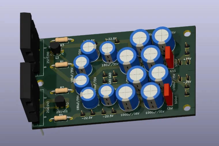
Capacitance Multiplier for Audio Power Amplifiers
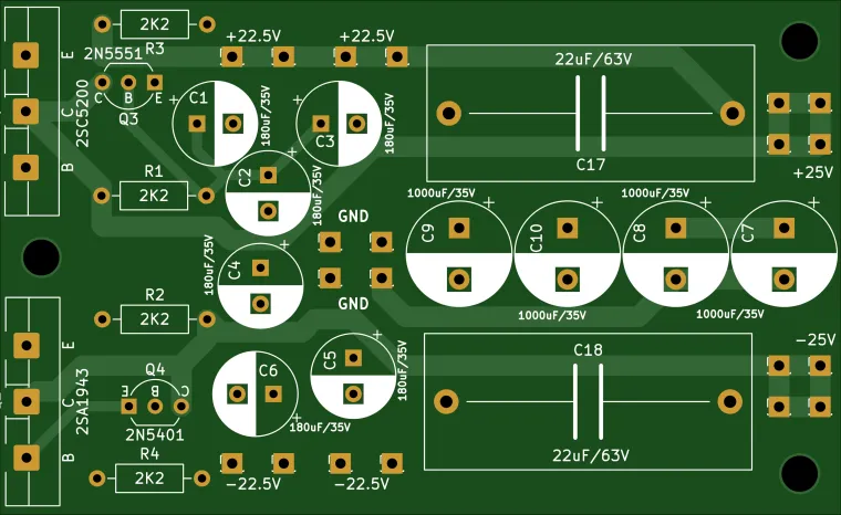
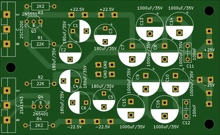
This project is a high-current capacitance multiplier PCB designed to reduce mains ripple, transformer hum, and power supply noise in audio power amplifiers using a classic ± supply for the output stage.
The circuit is intended for audiophile power amplifiers, including Musical Fidelity A1 amplifier and compatible clones, where clean and low-noise power delivery is required without the use of active voltage regulators.
The capacitance multiplier significantly improves power supply ripple rejection while maintaining low output impedance in the audio band. It operates without global feedback, ensuring stable operation and avoiding dynamic artifacts commonly associated with linear regulators.
The design is suitable for Class AB and Class A power amplifiers, including applications with high quiescent current, provided that adequate heatsinking is used for the pass transistors.
Key Features
-
Symmetrical ± power supply filtering
-
Excellent reduction of mains ripple and hum
-
Low noise and low output impedance
-
No switching noise, no HF artifacts
-
Suitable for high-current audio power stages
-
Designed for classic transformer-based power supplies
Important Notes
-
This circuit is not a voltage regulator; a voltage drop proportional to load current must be expected.
-
Pass transistors dissipate significant power and must be mounted on suitable heatsinks, especially in Class A applications.
-
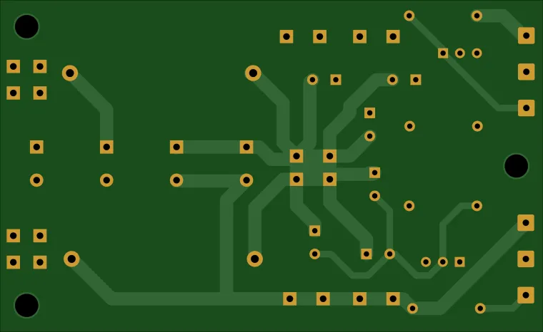
Proper grounding and short, low-resistance connections are essential for best performance.
Connection
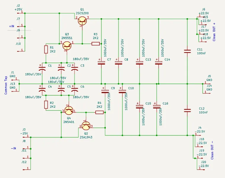
Connect the capacitance multiplier after the rectifier and main filter capacitors, and before the power amplifier output stage. The IN section is on tle left side of the schematic and the clean output OUT is on the right side of the schematic.
The PCB is intended for symmetrical ± supplies and should be mounted close to the amplifier.
Adequate heatsinking of the pass transistors is required, especially in Class A amplifiers.
Suitable for high-current power amplifier stages.
Maximum current depends on transistor choice, heatsinking, and operating conditions.
Disclaimer
This PCB is intended for experienced DIY audio builders.
The author takes no responsibility for improper assembly, incorrect component selection, or damage caused by misuse.
The circuit operates at potentially hazardous voltages and currents.
Heatsinking and component selection are the responsibility of the builder.