Add to cart
Board Type : GerberFile :
Layer : Dimensions :
PCB Qty :
Different PCB Design
PCB Thickness : PCB Color :
Surface Finish : Castellated Hole :
Copper Weight : 1 oz Production Time :
Total: US $
Elecrow community is a shared platform and we are not responsible for any design issues.

PCB Assembly

PCBA Qty: BomFile:
NO. OF UNIQUE PARTS: NO. of Components:
Assembly Cost: US $
Elecrow community is a shared platform and we are not responsible for any design issues.
Add to cart
3dPrintingFile : Size :
Unit : Volumn :
3D Printing Qty : Material :
Total: US $12.99
Elecrow community is a shared platform and we are not responsible for any design issues.
Add to cart
Acrylic Type : AcrylicFile :
Dimensions: Engrave:
Acrylic Qty :
Acrylic Thickness:
Acrylic Color:
Total: US $12.99
Elecrow community is a shared platform and we are not responsible for any design issues.
Add to cart
CNC Milling File : Size:
Unit: Volumn:
CNC Milling Qty : Material:
Type of Aluminum: Surface Finish:
Tolerance:
Surface Roughness:
Total: US $12.99
Elecrow community is a shared platform and we are not responsible for any design issues.
closed
user-img

cris

Published: Oct 09,2024

Traffic Lights Circuit using NE555

Small circuit, well known.

ccc ccc
Copyright Info

Attribution-ShareAlike (CC BY-SA)

Read More⇒
  110
  2
  0
cover-img
 
  • thumbnail-img
  • thumbnail-img
  • thumbnail-img
  • thumbnail-img
 

Hardware Components

  • NE555P

    X 1 fenxiang

Tools, APP Software Used etc.

  • Kicad

Story

Traffic Lights Circuit using NE555


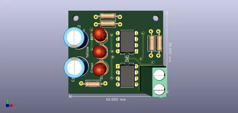
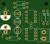
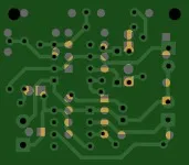
Here's a clever circuit using two 555's to produce a set of traffic lights for a model layout. The animation shows the lighting sequence and this follows the Australian-standard. The red LED has an equal on-off period and when it is off, the first 555 delivers power to the second 555. This illuminates the Green LED and then the second 555 changes state to turn off the Green LED and turn on the Orange LED for a short period of time before the first 555 changes state to turn off the second 555 and turn on the red LED. A supply voltage of 9v to 12v is needed because the second 555 receives a supply of about 2v less than rail. This circuit also shows how to connect LEDs high and low to a 555 and also turn off the 555 by controlling the supply to pin 8. Connecting the LEDs high and low to pin 3 will not work and since pin 7 is in phase with pin 3, it can be used to advantage in this design. 


I did not arrange the LEDs in line because I will use wires to solder them.

P.S. I am not the original author of this circuit, I just draw it.

Source: http://www.555-timer-circuits.com/traffic-lights.html

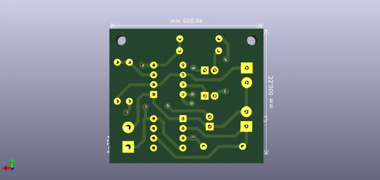
Schematic and Layout
user-img

cris

+ Follow

Topic

View All
NE555
  • Comments( 0 )
  • Like( 2 )
/1000
Upload a photo:
You can only upload 1 files in total. Each file cannot exceed 2MB. Supports JPG, JPEG, GIF, PNG, BMP

You May Also Like

View All