


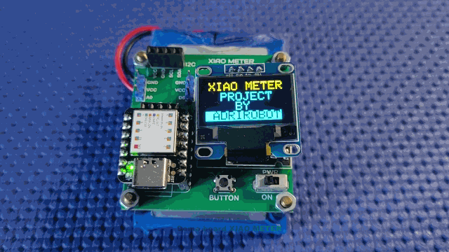
Story
Project Genesis
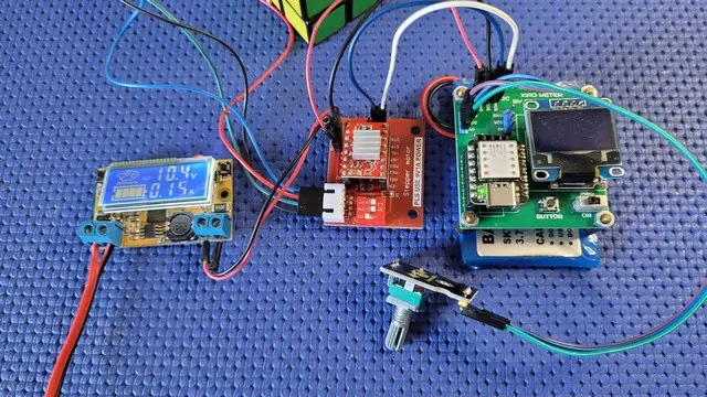
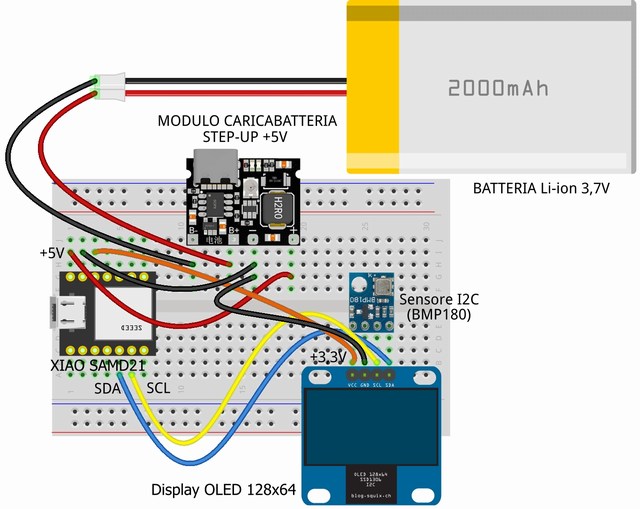
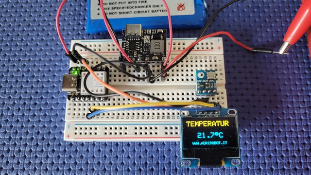
Before designing the PCB, preliminary testing was carried out using a breadboard, where components such as the microcontroller, power module, sensor, and display were assembled.
The basic functionality of the circuit was verified using a BMP180 sensor for temperature measurement.
The schematic, created with Fritzing, is shown below.
XIAO METER Demo Board Circuit Diagram
The schematic of the XIAO METER demo board replicates the one developed during the breadboard prototyping stage.
To design both the schematic and the double-sided PCB with plated-through holes, measuring only 48×49 mm, the online tool EasyEDA was used.
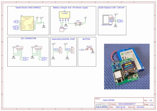
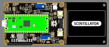
Processor Section
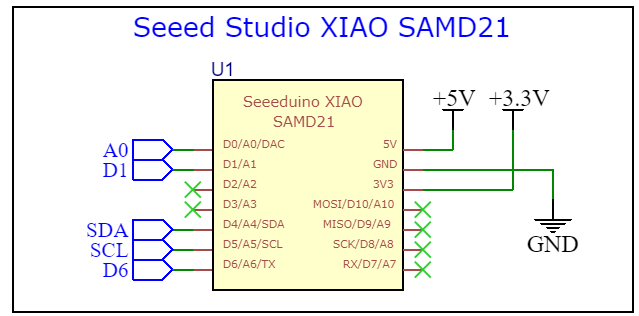
The processor section shows the utilized pins:
-
SDA and SCL pins for communication with sensors and the OLED display.
-
A0 analog pin,
-
D1 connected to the push button,
-
D6 for digital input.
Power connections include: -
+5V from the power/charging module,
-
3.3V output from the onboard voltage regulator,
-
GND.
The Seeed Studio XIAO SAMD21 is fully compatible with the Arduino IDE, making it easy to develop compact projects using the extensive Arduino libraries.
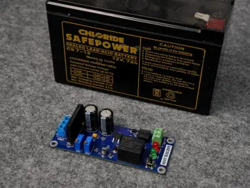
Power and Battery Charging Section
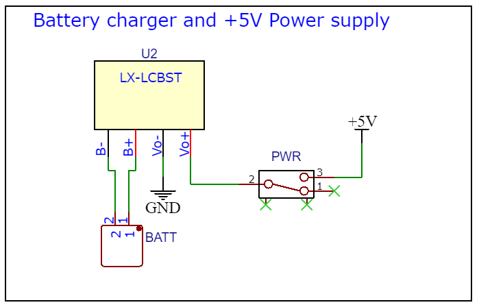
The power/charging section is based on the LX-LCBS module, which integrates circuitry for charging a Li-Ion battery and a Step-Up converter to raise the 3.7V battery voltage to the 5V required by the XIAO SAMD21.
The output voltage can be adjusted via a small trimmer on the module.
This section also includes:
-
A polarized battery connector,
-
A slide switch to disable battery power when not in use.
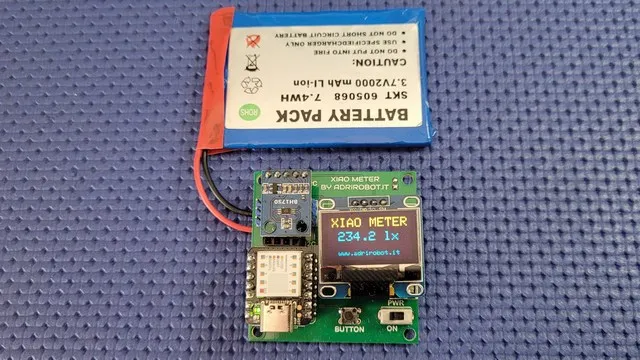
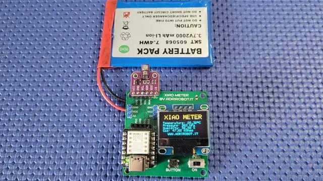
OLED Display Section – 0.96" 128×64 pixels
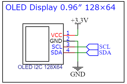
The OLED display section consists of just four lines:
-
SCL and SDA for the I2C bus,
-
3.3V and GND for power.
The display used is a 0.96" OLED, resolution 128×64 pixels, driven by the SSD1306 controller and interfaced via I2C.
I2C Connector Section
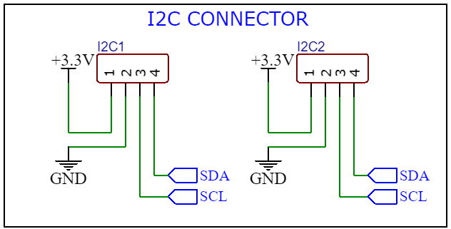
The demo board includes two 4-pin female headers for connecting sensors or modules that use the I2C interface.
Digital and Analog Connector Section

There are two male headers:
-
One for analog sensor modules connected to pin A0,
-
One for digital sensor modules connected to pin D6.
Push Button Section

The onboard push button is connected to digital pin D1.
No external pull-up or pull-down resistor is used, as the SAMD21 module provides an internal pull-up.
Assembly Steps
The images below show the simple steps required to assemble the XIAO METER Demo Board.


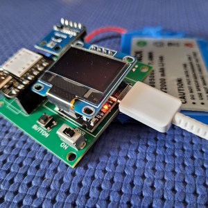
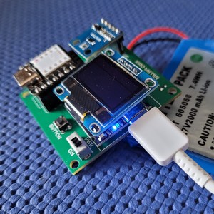
Battery Charger Test
The circuit is powered by a battery that can be charged via the LX-LCBS module. Charging is done through its USB port without disconnecting the battery.
-
A red LED lights up during charging.
-
A blue LED indicates that charging is complete.
 |
 |
For more information: XIAO METER Demo Board for XIAO SAMD21 – Complete Project