Low-cost PMR446 collinear with high gain, accurate impedance match, and a fully 3D-printed structure for reproducible builds.
Hardware Components
SO239 CONNECTOR
X 1
3mm brass tube
X 1
4 mm brass tube
X 1
Tools, APP Software Used etc.
NANO VNA V2
Story
The PMR446 band (446 MHz) is one of the few truly license-free radio communication options available in France. It allows the use of handheld radios (walkie-talkies) for short-range communication. However, this freedom comes with strict regulations: power is limited to 0.5 W ERP, antennas must be fixed and non-removable (for transmissions). In urban environments, the range rarely exceeds a few kilometers; under ideal conditions, it may reach up to 15 km.
This antenna was specifically designed to improve local reception on the PMR446 band. The design is based on rigorous RF principles—phasing, matching, impedance tuning—and has been fully characterized with a NanoVNA. It is easily reproducible thanks to 3D printing. Construction is inexpensive, using readily available materials such as 4 mm brass tube and 1.5 mm² copper wire. All necessary files for 3D print are provided, enabling anyone to build a functional version.
📶 Why Stack Radiating Elements?
Stacking multiple vertical radiators along the same axis — the core principle behind collinear antennas — concentrates energy toward the horizon and flattens the vertical radiation pattern. A simple quarter-wave whip (¼ λ) produces a lobe at approximately 25° elevation with a reference gain of 0 dBd. Upgrading to a half-wave (½ λ) shifts the main lobe down to ≈ 15° and yields a gain of about +2 dBd. By chaining together three identical and correctly phased sections, typical gains reach around +6 dBd, with a main lobe just 3–5° above the horizon.
This constructive superposition of fields is what makes collinear designs attractive for increasing horizontal range.
However, this gain does not scale indefinitely. Beyond a few sections, geometric and phase alignment errors accumulate, side lobes begin to grow, and mechanical constraints or signal cancellation reduce overall efficiency. That’s why most practical collinears stop at two or three (sometimes five for commercial device) radiating sections.
Radiation Angle vs Gain (Illustrative)
Configuration
Elevation Angle (°)
Gain (dBd)
Notes
¼ λ monopole
~25°
0 dBd
Basic whip, wide lobe
½ λ vertical
~15°
+2 dBd
Narrower lobe
2 × 5/8 λ collinear
~8–10°
+4–5 dBd
Requires phasing stub
3 × 5/8 λ collinear
~3–5°
+6–7 dBd
Flatter lobe, compact design
≥ 4 × 5/8 λ (theoretical)
<3°
+7–8 dBd
Diminishing returns + complex + length
🛑📡The Non-Radiation of the Folded Stub: Physical Justification and Current Integral
In the folded stub (three parallel conductors connected by two 180° bends), the cancellation of radiation does not arise from differences in optical path: since the conductors are very close together (d ≪ λ), every point on the stub is virtually at the same distance from the far-field observer, so the geometric phases are aligned.
The real mechanism is linked to the current distribution: as you move along the stub, the current reverses direction at each change of conductor (up, down, up again). Mathematically, this is expressed by a far-field integral :
where I(z) alternates in sign along each straight segment due to the folded geometry.
As a result of this alternation (harmonic character of the current plus the inversion of its direction along the stub), the integral of the contributions from the three straight sections is nearly zero over the whole stub, and the bends only contribute negligibly : on the order of kd power 2.
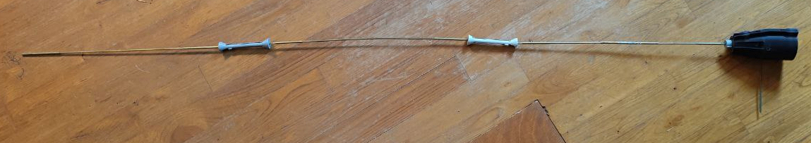
In this image, the stub is visible, with the copper wire guided along the structure. On the right, a 4 mm brass tube is inserted into the PLA body. The tube is then crimped onto the copper wire using a crimping tool (if you don’t have one, a standard pair of pliers can be used instead).
Description
The PMR446 band (446 MHz) is one of the few truly license-free radio communication options available in France. It allows the use of handheld radios (walkie-talkies) for short-range communication. However, this freedom comes with strict regulations: power is limited to 0.5 W ERP, antennas must be fixed and non-removable (for transmissions). In urban environments, the range rarely exceeds a few kilometers; under ideal conditions, it may reach up to 15 km.
This antenna was specifically designed to improve local reception on the PMR446 band. The design is based on rigorous RF principles—phasing, matching, impedance tuning—and has been fully characterized with a NanoVNA. It is easily reproducible thanks to 3D printing. Construction is inexpensive, using readily available materials such as 4 mm brass tube and 1.5 mm² copper wire. All necessary files for 3D print are provided, enabling anyone to build a functional version.
📶 Why Stack Radiating Elements?
Stacking multiple vertical radiators along the same axis — the core principle behind collinear antennas — concentrates energy toward the horizon and flattens the vertical radiation pattern. A simple quarter-wave whip (¼ λ) produces a lobe at approximately 25° elevation with a reference gain of 0 dBd. Upgrading to a half-wave (½ λ) shifts the main lobe down to ≈ 15° and yields a gain of about +2 dBd. By chaining together three identical and correctly phased sections, typical gains reach around +6 dBd, with a main lobe just 3–5° above the horizon.
This constructive superposition of fields is what makes collinear designs attractive for increasing horizontal range.
However, this gain does not scale indefinitely. Beyond a few sections, geometric and phase alignment errors accumulate, side lobes begin to grow, and mechanical constraints or signal cancellation reduce overall efficiency. That’s why most practical collinears stop at two or three (sometimes five for commercial device) radiating sections.
Radiation Angle vs Gain (Illustrative)
Configuration
Elevation Angle (°)
Gain (dBd)
Notes
¼ λ monopole
~25°
0 dBd
Basic whip, wide lobe
½ λ vertical
~15°
+2 dBd
Narrower lobe
2 × 5/8 λ collinear
~8–10°
+4–5 dBd
Requires phasing stub
3 × 5/8 λ collinear
~3–5°
+6–7 dBd
Flatter lobe, compact design
≥ 4 × 5/8 λ (theoretical)
<3°
+7–8 dBd
Diminishing returns + complex + length
🌀Capacitive Matching of the Radiating Element and Impedance Autotransformer
A vertical monopole antenna resonates ideally when it measures a quarter-wavelength (¼ λ): at this length, the input impedance is largely resistive and well matched (typically 36 Ω with a perfect ground plane) and has very little reactive component. However, as soon as the element is lengthened beyond λ/4—up to about 5/8 λ, as is the case here for our first section to optimize the radiation pattern—the tip of the element accumulates significant charge, creating a capacitive reactance: the feedpoint “sees” a typical impedance of about 200 Ω – j150 Ω. In other words, a strong –jX component appears, analogous to having a capacitor between the tip of the element and the ground plane.
To compensate for this capacitance and restore resonance, a tuning coil (series inductor) is inserted between the coaxial core and the base of the radiating element. This coil provides the necessary +jX reactance to cancel out the capacitive part, making the input impedance purely resistive at the operating frequency.
In this project, the coil is made by winding six turns of 1.5 mm² copper wire around a 3D-printed PLA support, forming a cylinder 43 mm high and 5 mm in diameter. This design is the result of many practical trials: it took me about twenty iterations to find the ideal value. I fine-tuned experimentally by systematically measuring the return loss (S11) with a VNA after each modification. The right compromise was eventually achieved by combining sufficient height (43 mm), a compact diameter, and a number of turns providing both the required capacitance compensation and impedance matching.
In this picture, we can see the end of the copper wire connected to the central pin of the SO-239 connector. It runs through the PLA mandrel and is ready to be soldered onto one of the turns of the helical coil. The PLA structure includes a dedicated "soldering window" that allows for mechanical clearance and electrical adjustment. This window enables tuning of the antenna's impedance by shifting the tapping point along the coil. Interestingly, even without any matching instrument, early tests show very good results when the tapping point is positioned within the soldering window — confirming that the antenna performs well in this configuration.
An added advantage of this coil: it also acts as an impedance autotransformer. The coaxial core is not soldered at the bottom or top of the coil, but on an intermediate turn, which allows the high impedance (~200 Ω) of the tuned element to be transformed to a value close to 50 Ω for the cable. By moving this “tap” up or down a turn, it is possible to fine-tune the matching and achieve an optimal SWR, typically below 1.3 (and with the present case close to 1.0). The "window" in the PLA part is set at the right position in order to achieve the impedance match easily.
This tuning system ensures both resonance, mechanical robustness, and precise impedance matching at 446 MHz. Moreover, thanks to the window made in the antenna body and the coil former, it is easy to reproduce: the soldering on the selected turn is greatly simplified, making this build accessible even without specialized tools (VNA)
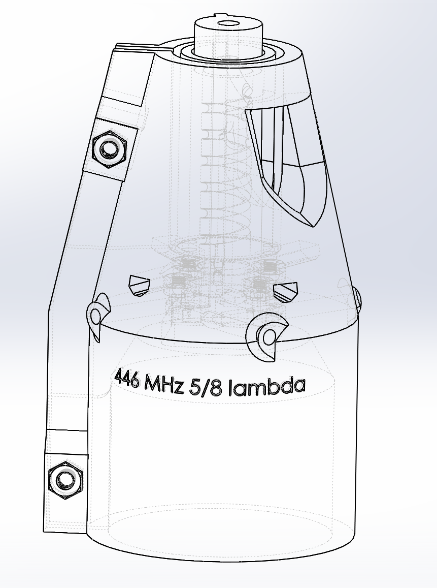
Mechanical Structure & CAD
The mechanical structure is fully designed for PLA 3D printing on an Ender-3 (30% gyroid infill, total print time ≈ 24 h; also compatible with any printer supporting 200 mm height). The central body is cylindrical and features, at its base, a securely fastened SO-239 connector that serves as the RF ground reference.
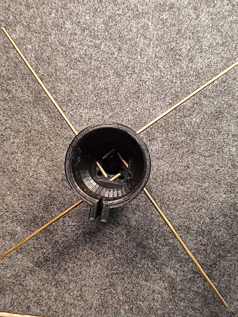
Four brass tubes, each 4 mm in diameter 150 mm lenght, are clamped between the PLA and the connector to create the ground plane, ensuring both mechanical strength and electrical contact.
Just above the SO-239, an internal former supports the tuning coil: a wide slot is included for easy access with a soldering iron, allowing you to precisely locate and solder the tap without disassembling the assembly. This same former also supports the first vertical element, which is then continued by the folded stubs.
The entire assembly is enclosed in a 20 mm diameter PVC tube (“tubiro”), which is easy to find in hardware stores and protects the electrical elements from the weather. For extra sealing and durability, the PLA parts are primed with a plastic primer, and then painted: this ensures long-term resistance to UV and moisture, with no significant mechanical stress (the top cap locks the tube and supports any force from the mast). All CAD files are provided in AMF format, along with ready-to-use G-code.
Element
Length (mm)
Notes
1
405
From the top edge of the coil to the bottom of stub 1
2
397
From the top edge of stub 1 to the bottom edge of stub 2
3
392
From the top edge of stub 2 to the tip of element 3
Note: Tuning must be done with the 20 mm tube (we say "Tubiro" in France) in place, as it affects antenna tuning and resonance frequency.
The total antenna length is 153.5 cm, and the PVC tube should be cut to 145.5 cm.
📈 Measurement, Tuning, and Performance with the NanoVNA 2
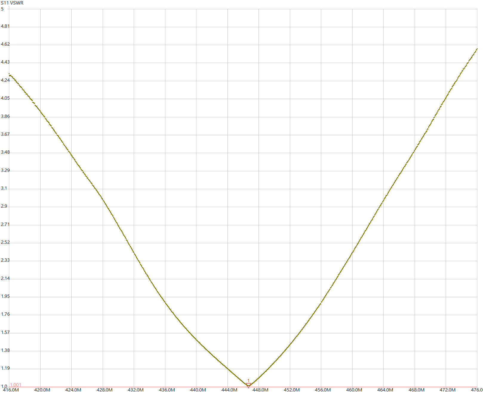
Tuning is carried out using a NanoVNA 2 connected to a computer (NanoVNA-Saver). After short-open-load calibration, the reflection coefficient S11 is observed across the 416–476 MHz range. Each element is gradually trimmed to center the resonance at 446 MHz (achieving nearly pure impedance), and the tap point on the coil is adjusted to bring the impedance to 50 Ω. SWR (~ 1.0 !). NanoVNA-Saver allows to save SWR plots and analyze bandwidth, resonance quality, and phase.
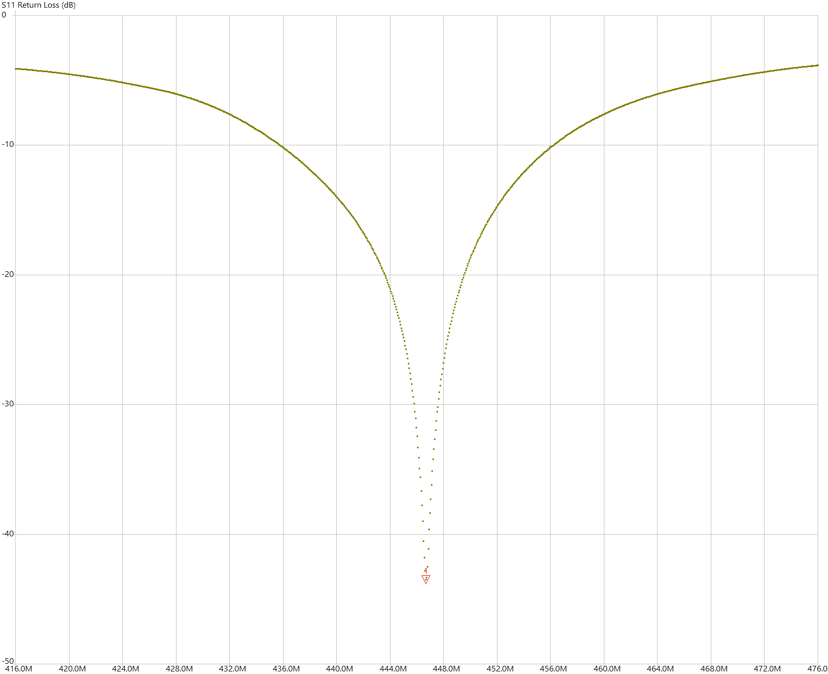
All five plots were taken with the red marker fixed at exactly 446.684 MHz. The numeric read-out at that marker is summarised below:
Return Loss (S11) — The trace shows a very deep, narrow notch centred at 446.684 MHz, reaching –43.5 dB. Less than 0.01 % of the power is reflected; virtually all of it is delivered to the antenna. Such performance is typical of precise tuning and excellent impedance match.
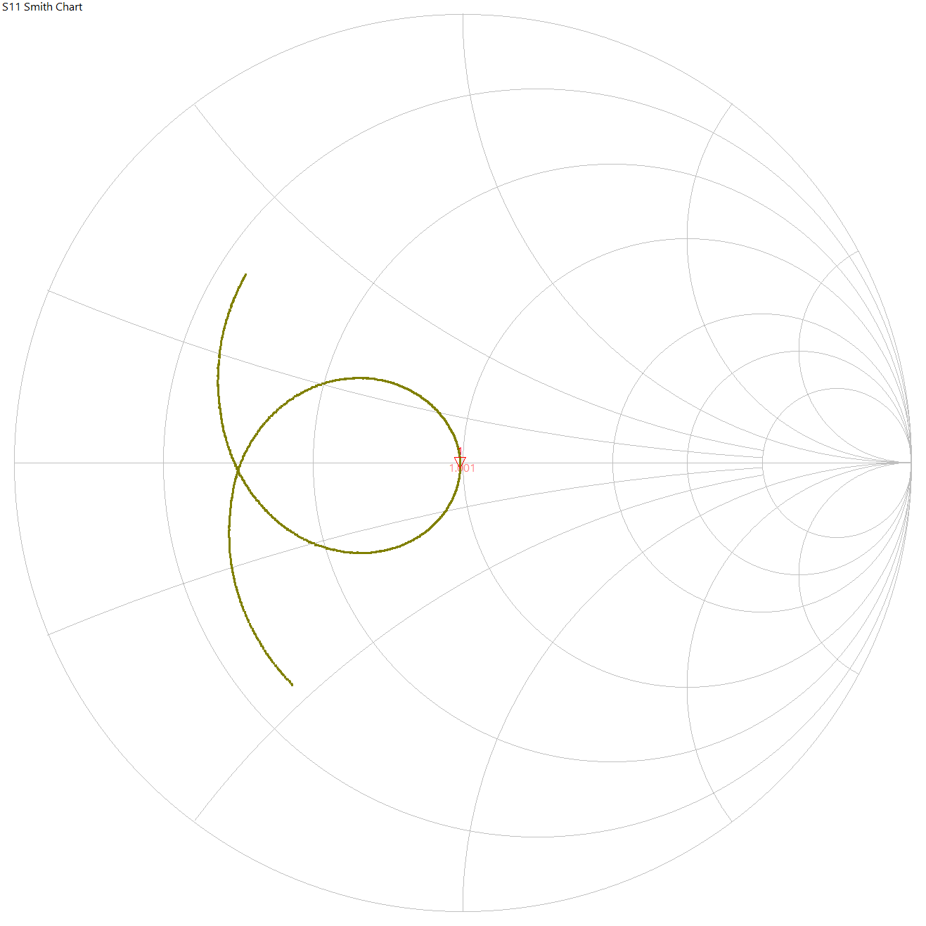
Smith Chart — The Smith Chart shows a clean crossing of the centre (50 Ω) with a moderately wide loop, indicating a sharp resonance and well-controlled impedance. The extended trajectory confirms good matching over a wide bandwidth.
The S11 phase response shows a steep transition around resonance (446.684 MHz). This confirms a well-defined resonance.
VSWR — The curve bottoms out at 1.013 at the marker, indicating an almost perfect impedance match. The symmetric rise on either side confirms a tight, single-frequency tune.
The experimental results are attached in S1P format.
Taken together, the plots demonstrate an exceptionally good level of tuning: a return loss below –40 dB, a VSWR very close to 1:1, and an impedance almost exactly 50 Ω at 446.684 MHz. Such performance is rarely achieved outside of lab conditions and it ensures negligible mismatch losses at the target frequency.
This antenna exhibits a "pancake"-shaped radiation pattern with a low take-off angle (3–5°), a practical gain of +6 to +7 dBd, and a VSWR ≤ 1.5 bandwidth of approximately 3 MHz. With a 0.5 W input and a theoretical gain of +8 to +9 dBi, it can provide excellent horizontal coverage. However, it’s designed for reception only — transmitting with it would exceed the legal ERP limit for PMR446 (typically capped at 0.5 W ERP).
I’ve built and tested several antennas of both the 2×5/8 λ and 3×5/8 λ collinear types, and consistently achieved similar matching results across units using identical elements. This confirms that the dimensional accuracy of the printed base, matching section, and mechanical supports is sufficient to ensure repeatable performance : Even without any tuning or VNA checks — the SWR usually lands between 1.0 and 1.3, which is quite remarkable for a blind-tuned design.
Conclusion
With this 3×5/8 λ collinear antenna, you get a PMR 446 whip with significant horizontal gain, along with comprehensive documentation (CAD, measurements, principles). It’s a project accessible to makers who want to go beyond the range of a stock antenna for a very low cost (~11 €). Have fun and share your results (and if you live in a free country you can even make transmission tests) !
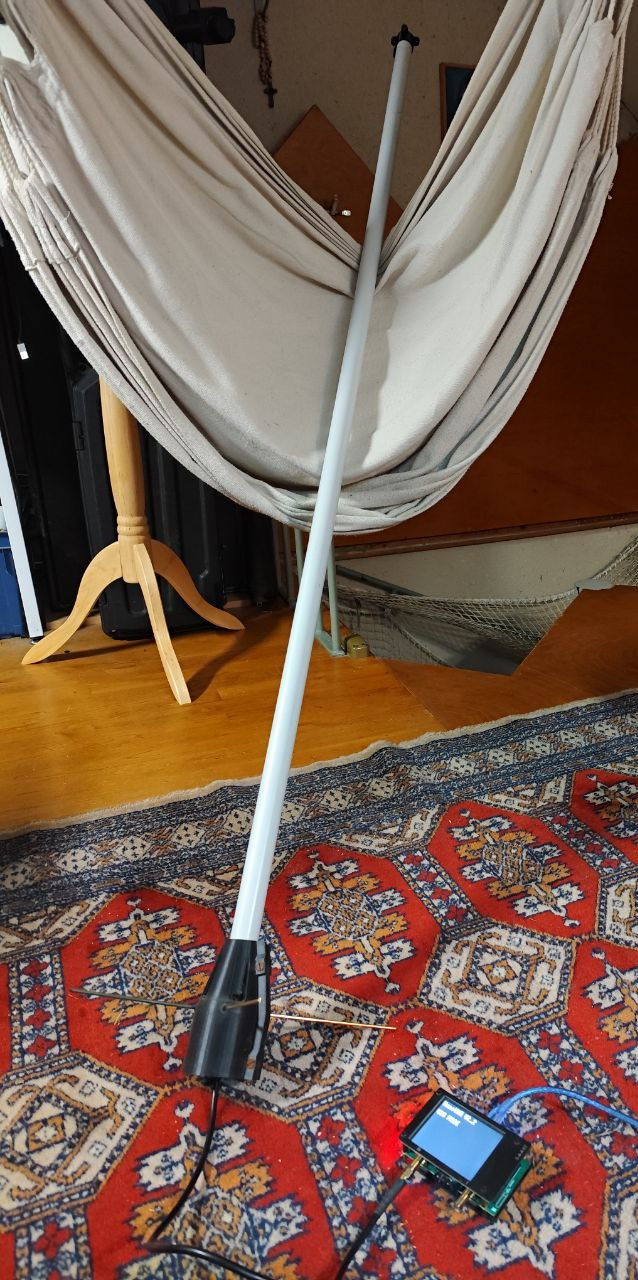
All measurements were conducted outdoors under open-field conditions to ensure accuracy. The photo, however, was taken indoors… because I forgot to snap one during the actual field tests.
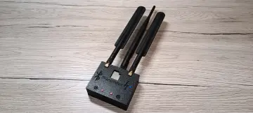
I also designed a 12 dB Yagi antenna for PMR on a 2-meter aluminum boom. It follows the same principle: PLA printed parts, a brass driven element, and other elements made from recycled 4 mm aluminum welding rods. It works remarkably well, with good feed symmetry and proper impedance matching using a 1:1 balun. If you’re interested, I can share the plans as well.