
Story
Today I received a shipment with a Small round LCD display from Elecrow. The device is packed in two boxes so that it is fully protected from damage during transportation. Inside there is a display, a USB cable for power and communication, as well as an additional cable for connecting an external module.
This is CrowPanel 1.28inch-HMI ESP32 Rotary Display 240*240 which has some really impressive features:
- high-performance ESP32-S3 chip
- WiFi and low-power Bluetooth
- capacitive touch screen with knob
- 5 WS2812 RGB Leds
- and the Rotary encoder in the form of a circular ring

It supports Arduino IDE, Lua RTOS, Home Assistant/PlatformIO/Micro Python, and LVGL library. When the device is turned on for the first time, a demo application is installed that presents several basic features on the display. Thanks to the high resolution, the image on the display is clear and beautifully visible from different angles.
This is my first time encountering this display, so I decided to use it to create a device that would demonstrate all of its features. Otherwise, as a passionate Shortwave listener, I was impressed by the original idea of T Uebo from TJlab for making a VFO with virtual retro circular scales.
The circular shape of this display is ideal for making such a device, so I decided to make a similar but also usefu l and functional device based on the previously mentioned project. The fact that this display contains a built-in rotary encoder, buttons and a touch screen makes it even more usable for this purpose. Also very important is the fact that we only need to solder a few wires to make a fully functional VFO so that even a beginner in this field can easily make it.
So to make the device, we generally need only two components
- CrowPanel 1.28inch-HMI ESP32 Rotary Display 240*240
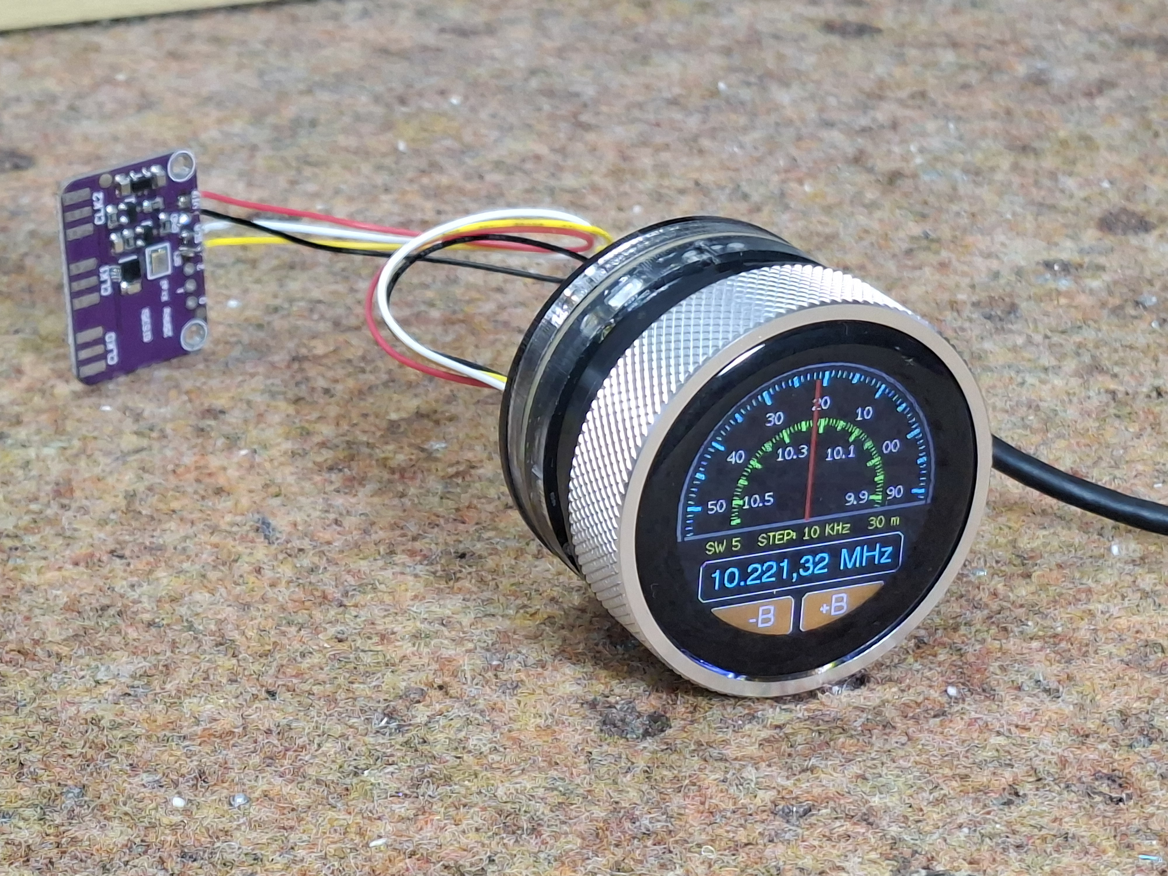
- and SI5351 Clock Generator module
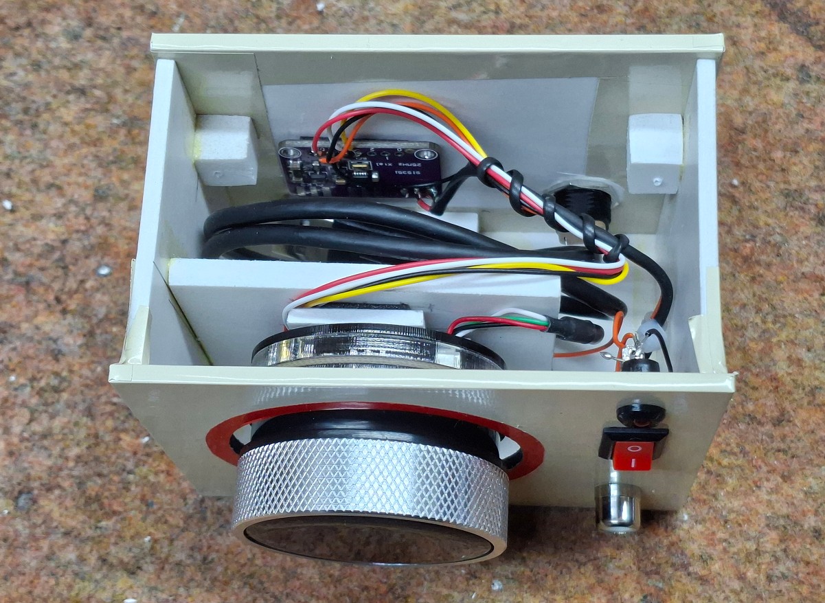
Of course, if we want the device to be independent and universal, we need to install a 3.7V lithium battery, a switch and a suitable connector. The device should be installed in a small suitable box. It's useful to also include a small battery charger module in the box (I didn't have one at the time) that costs less than a dollar.
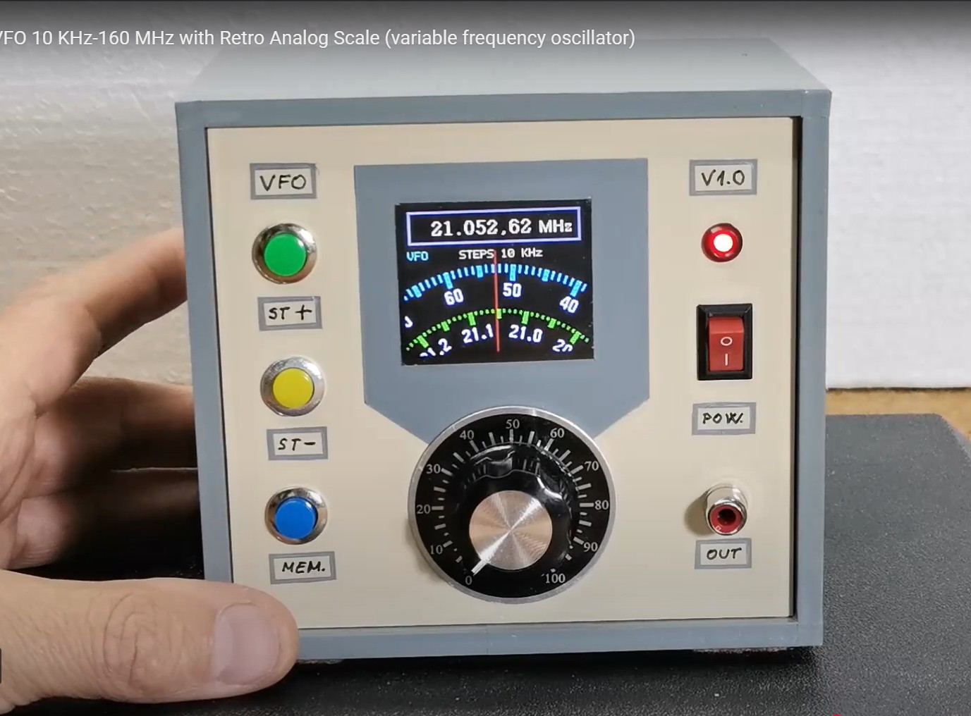
Let's see what the display looks like with all the information and functions. Immediately after switching on, we get a lot of information on the display. First of all, there is a window with two virtual scales that rotate in a ratio of 1 to 10. Both scales are marked in tenths. In the middle of the scale there is a vertical red line that indicates the exact frequency of the scales.
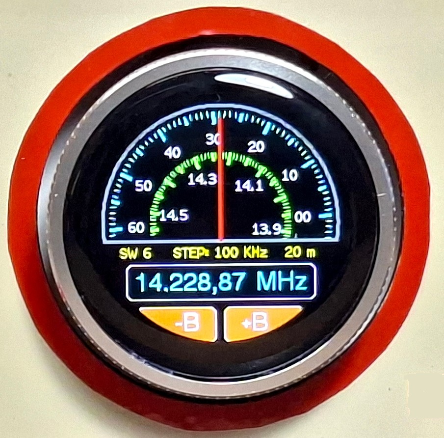
In the lower part of the display, is presented the generated frequency with large blue numbers. Immediately above this information, on the sides in yellow letters, is the Band and Wavelength, and in the middle is shown the step with which the scales move when turning therotary encoder. At the bottom are two buttons B+ and B- which are touch-sensitive and are used to change the band.
Now let's see how this device works in real conditions. The initial band and frequency are entered in the code and can be changed as desired. The default step of the scales movement is 1Khz. The entire screen represents a large button that I specifically used to change the step value. This value can be changed from 10Hz to 1MHz. The speed of rotation of the scale changes proportionally to the step. At every moment, the scale shows the exact generated frequency. At the bottom of the display are two buttons with which we can change the band. When touching the button, it briefly changes color to red to let us know that it is activated. At the same time, the frequency, band and scale change. I determined the width of each band to be maximum so that when one band ends, it immediately continues to the next. I did this so that we can continuously scan all frequencies. The transition from one band to another is signaled by a short flash of red on the corresponding button. Let me emphasize that the touch function only responds to the lower part of the screen where the buttons are drawn.
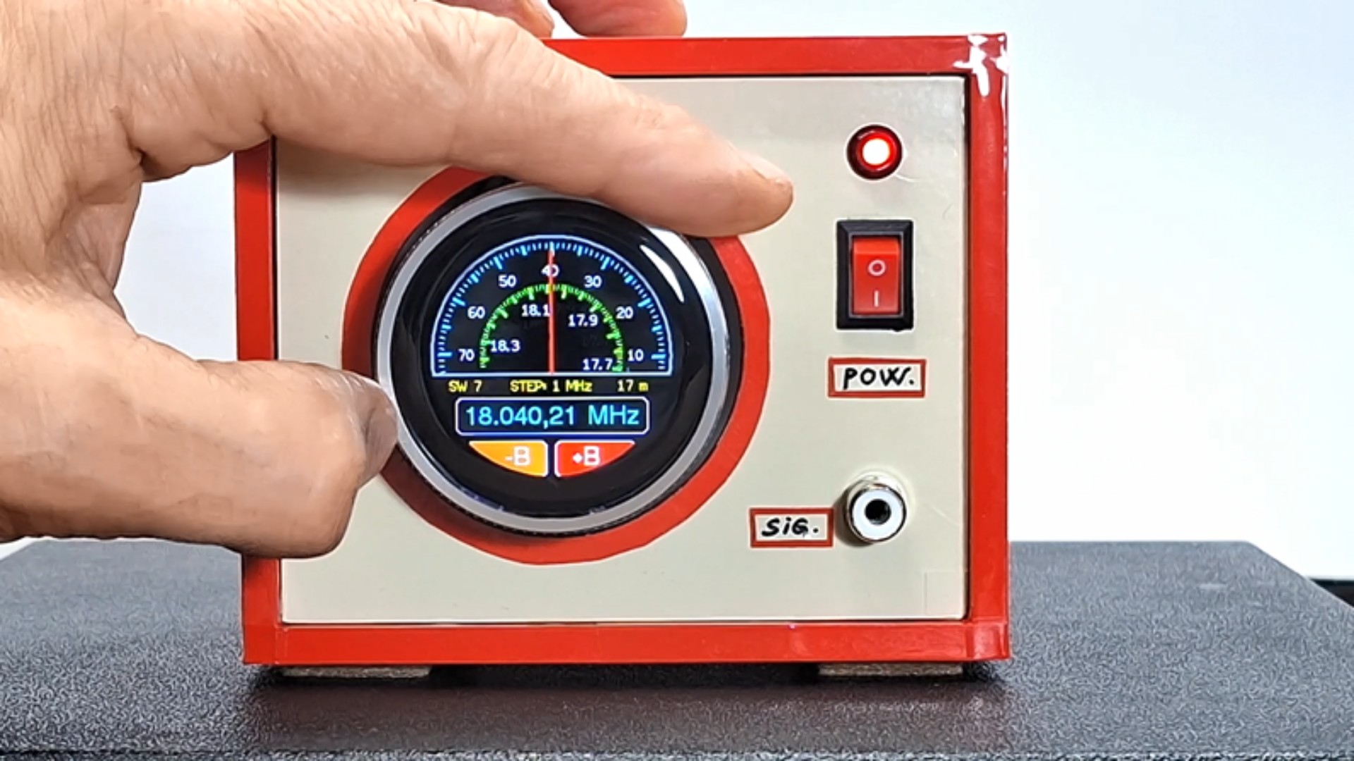
So as you can see, we have all the functions of this small display module. The rotary encoder responds very easily and precisely, and it is also robustly made in such a way that the specially processed inner edge of the ring (dial) activates two microswitches, which guarantees long-term operation. The image on the screen is extremely clear and readable from every angle, and the touch is of the capacitive type and responds immediately when the finger approaches the buttons.
As for the code, I made it in a way that allows you to change many parameters very easily.
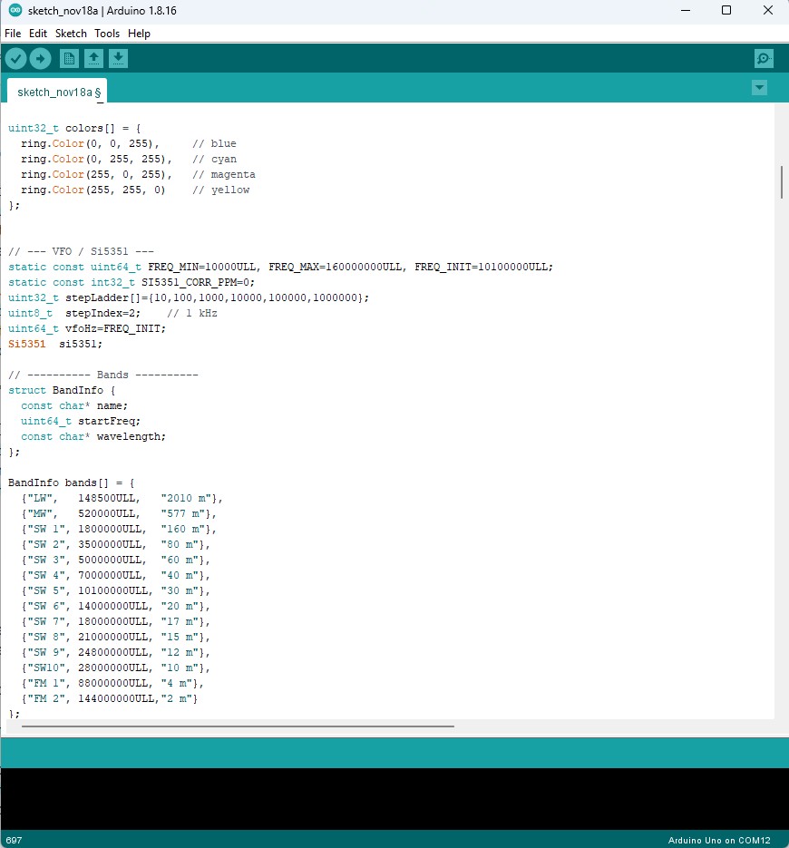
It is important to emphasize that in order to compile the code without errors, you need to use ESP32 Core V 2.0.14 along with the provided libraries. I should say that this is the first version and I hope to make many more improvements in terms of visual and functional aspects in the future.
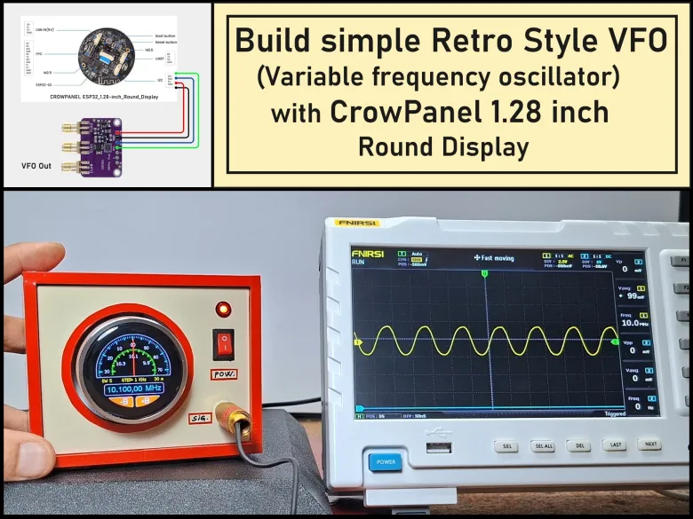
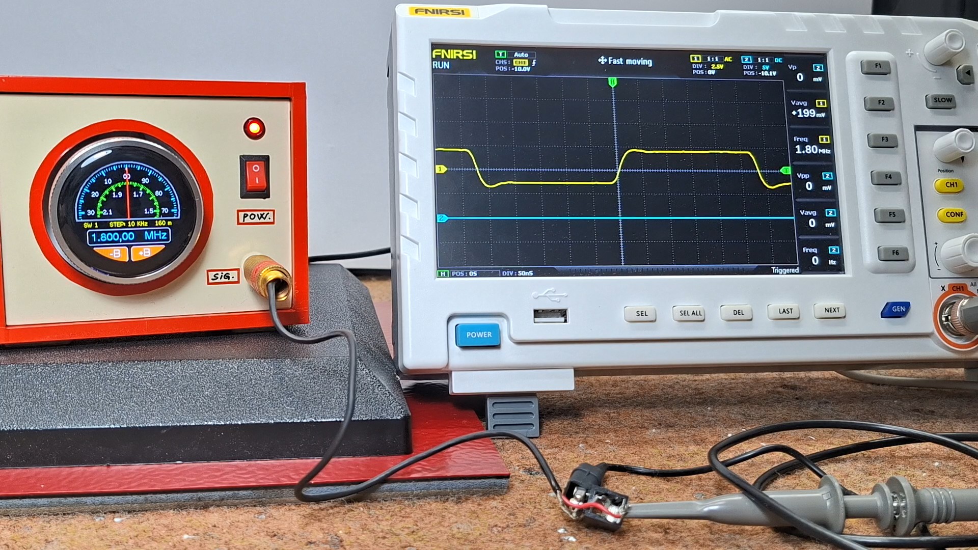
Next, let's trace the shape of the output signal on an oscilloscope. It is clear that it depends exclusively on the Si5351 module and to some extent on the library that drives it. The frequency range of the generated signal is impressive and can range from a few tens of kilohertz to over 160 Megahertz.
And finally a short conclusion. This is easy-to-build VFO (Variable Frequency Oscillator) that features a clear, touch-enabled circular display with retro-style virtual scales. The combination of the CrowPanel ESP32 display and the Si5351 module allows for a wide frequency range and precise control with minimal wiring.