


Story
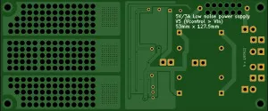
Low Noise 5V / up to 3A Linear Power Supply for Raspberry Pi Audio Streamer
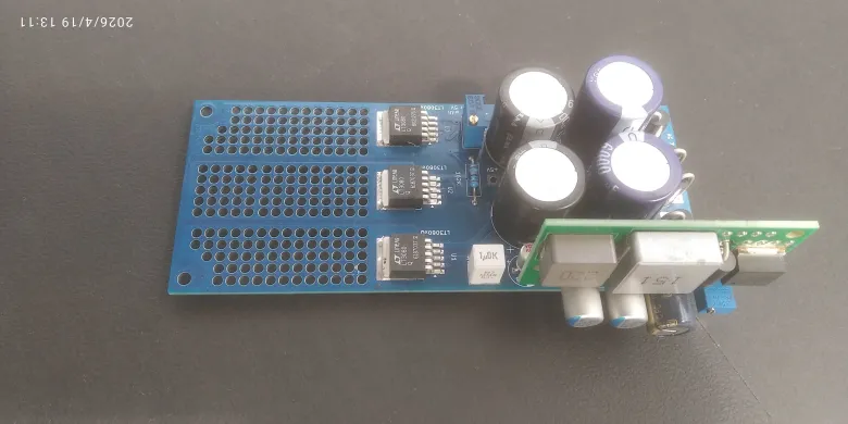
This project is a low-noise linear power supply designed for an audio streamer based on Raspberry Pi 3B+ and also suitable for Raspberry Pi 2B / 3B. The regulator stage is built from three LT3080Q LDO regulators connected in parallel to provide up to approximately 3A output current with very low noise and good thermal behavior.
Design concept
This power supply was designed as the linear post-regulator stage for my separate DC-DC Pre-regulator project. (also shared) The main purpose of the DC-DC preregulator is to reduce the rectified voltage coming from the transformer and bridge rectifier to the lowest practical value before the LT3080Q stage. This minimizes voltage drop across the linear regulators and therefore minimizes heat dissipation, while still keeping the very low noise advantages of a linear supply.
Why a preregulator is used here
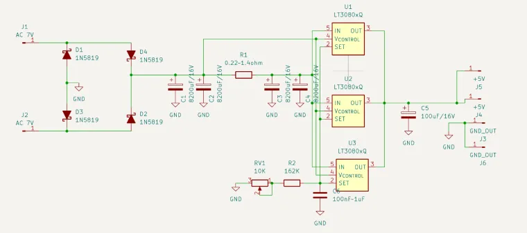
The LT3080 can operate in two different modes. In 3-terminal mode, the VCONTROL pin is tied to IN, and the dropout is about 1.35V. In the better split-supply mode, VCONTROL is powered from a higher voltage while the main power path at IN is supplied from a lower voltage. In this mode, the dropout on the IN pin is only about 350mV typical, which is one of the key reasons for using the DC-DC preregulator in this project.
So in this design the preregulator does two important jobs:
- It reduces the input voltage from the transformer and bridge rectifier to only the minimum needed by the LDO stage, so the voltage drop and heat on the LT3080Q regulators stay very low.
- It also allows the VCONTROL pin to be supplied from a higher voltage rail ahead of the final low-drop linear stage, so the LT3080 can work in its more efficient split-supply mode.
In practice, the DC-DC preregulator is adjusted so the LT3080Q IN pin sees only a very small headroom above the final 5V output, while VCONTROL is kept somewhat higher. This is exactly the operating method recommended in the LT3080 datasheet to increase efficiency and reduce dissipation. :contentReference[oaicite:2]{index=2}
Output voltage setting with 3 parallel LT3080 regulators
The LT3080 uses a precision current-source architecture. For a single regulator, the datasheet gives:
VOUT = RSET × 10µA :contentReference[oaicite:3]{index=3}
In this project, three LT3080Q regulators are connected in parallel and their SET pins are tied together. Each LT3080 contributes its own approximately 10µA SET pin current, so the total programming current is about 30µA. Therefore the output voltage is set approximately by:
VOUT ≈ RSET × 30µA
This is why the resistor value used here is about three times higher than it would be for a single LT3080 set to the same output voltage. With the shown resistor network, the adjustment range is appropriate for fine trimming around a 5V output. The use of three parallel LT3080 devices is therefore important not only for current capability, but also for the way the final output voltage is programmed. This follows directly from the datasheet architecture: one resistor programs output voltage, and each LT3080 sources about 10µA from its SET pin. :contentReference[oaicite:4]{index=4}
Why three LT3080Q in parallel?
The LT3080 is specifically intended for paralleling. According to the datasheet, multiple devices can be connected in parallel to increase output current and spread heat. In this project, three LT3080Q regulators share the load current, which improves thermal distribution and allows the supply to deliver up to about 3A for Raspberry Pi based audio applications. :contentReference[oaicite:5]{index=5}
Estimated output noise
The LT3080 datasheet specifies typical 40µV RMS output noise in the 10Hz to 100kHz band when a bypass capacitor is used on the SET pin. In a 3-device parallel arrangement, the practical output noise can be estimated as decreasing by approximately sqrt(3) if the regulator noise contributions are treated as largely uncorrelated. That gives an estimated noise of about:
40µV / sqrt(3) ≈ 23µV RMS
So the complete 5V regulator stage can be expected to have output noise on the order of 23µV RMS (10Hz to 100kHz). This is an engineering estimate based on the LT3080 datasheet noise figure for one device and the usual RMS averaging assumption for parallel regulators. Real final noise will also depend on layout symmetry, grounding, rectifier behavior, transformer quality, and the external preregulator performance. :contentReference[oaicite:6]{index=6}
Thermal advantage
Because the preregulator reduces the voltage before the linear stage to only the minimum required in split-supply LT3080 operation, the final LDO stage dissipates much less power than a classic linear supply fed directly from the rectified transformer voltage. This is the main reason why this supply can provide high current with very low noise and still remain only slightly warm in normal operation.
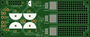
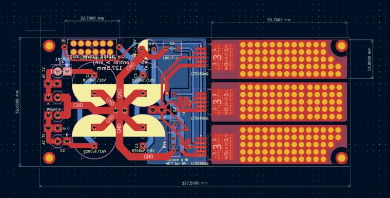
Important PCB note
Some PCB traces in this design are intentionally used as ballast resistors to help equalize current between the three parallel LT3080Q regulators. Because of that, the copper thickness must not be changed from the value used when designing the PCB. Use standard 1 oz copper. Do not switch to thicker or thinner copper unless the ballast trace resistance is recalculated, because the resistance of these traces is part of the current-sharing design. The LT3080 datasheet also discusses current sharing by using trace resistance when paralleling regulators.
Main parts used
- 3x LT3080Q linear regulators in parallel
- 4x large input reservoir capacitors
- 100µF output capacitor
- SET bypass capacitor
- Schottky bridge rectifier using 1N5819 diodes
- DC-DC preregulator described in my separate shared project
Recommended use
This supply is intended mainly for low-noise digital audio applications, especially Raspberry Pi based streamers such as piCorePlayer / LMS endpoints. It is a good solution where low noise, low heat, and stable high-current 5V supply are more important than maximum efficiency.


