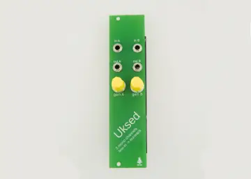
Story
Revision 1 of this design works but requires a respin to fix a few issues
Changes I'll make in the Rev2 design
- add + and - silkscreen to the pads on the lipo battery so you know the polarity
- add a stronger LDO, the CAT6219-330TDGT3
- all tracks should be thicker then 6 or 7 mil
- remove pin 7 on H3, this will mark the polarity for burning the bootloader using the Segger J-link
- three seperate leds are necessary, right now D13 only lights when connected to USB, D13 one end to +3.3V
- flex cable on oled is tight, slot or board notch possibly needed
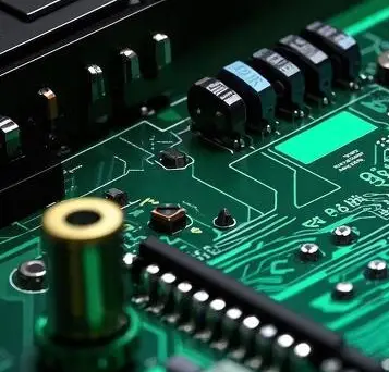
Assembly instructions
- order the board from OSH Park here: https://www.oshpark.com/shared_projects/SkULVRHA , the price for three 4 layer pcbs is $12.50
- follow the bom when ordering and hand stuffing components, solder on the oled display but do not tape it down
- burn in the bootloader using the Segger J-link, Digi-Key #899-1008-ND, 899-1012-ND
- follow the bootloader instructions: https://learn.adafruit.com/proper-step-debugging-atsamd21-arduino-zero-m0/restoring-bootloader
- pogo pins are needed for the bootloader: MILL_MAX 855-22-010-10-001101
- connect the board to the Arduino IDE, pick Adafruit Feather M0 as the board, choose the right com port and load in the sketch and if the display works tape it down
GitHub Link: https://github.com/mike-rankin/SAMD21G18A_Sensor_Board/tree/master This is GitHub account: https://github.com/mike-rankin where you will explore more excellent projects. He is a good DIY maker who designs custom ESP32 IoT projects using Altium Designer, Arduino IDE and Fusion360. Welcome everyone to follow.