Story
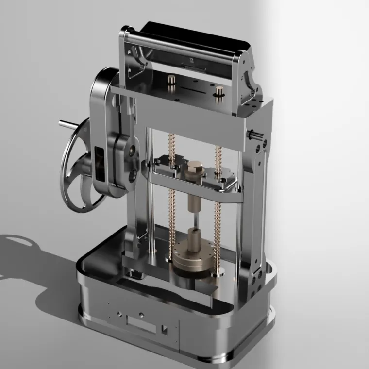
The presented model is a meticulously engineered Manual Universal Testing Machine (UTM) designed for conducting fundamental mechanical tests such as tension, compression, and shear on a wide range of materials. Although manual in operation, the structure and mechanism demonstrate industrial-level precision, robust stability, and thoughtful integration of mechanical principles. The machine’s design shows a careful balance between functionality, manufacturability, and visual appeal, reflecting a professional-grade product suitable for laboratory and educational environments.
1. Overall Structure and Body
The main frame consists of a rigid vertical housing, constructed with a heavy-duty metallic body that provides structural strength and minimizes unwanted vibration. The aesthetic surface finish—likely polished stainless steel or chrome-coated steel—adds a sleek, reflective character while also improving corrosion resistance.
The machine rests on a wide rectangular base, which acts as both a stabilizing foundation and a platform to accommodate reaction forces generated during loading. The base edges exhibit smooth fillets, enhancing both safety and appearance. The front face of the base prominently displays the engraved text “MANUAL UNIVERSAL TESTING MACHINE,” giving the device a professional identity.
2. Twin Screw and Column System
The machine relies on a dual vertical screw-column arrangement, visible in bronze or brass coloration. These threaded screws are positioned symmetrically on either side of the loading platform. They serve two major functions:
-
Providing vertical motion to the movable crosshead, ensuring smooth, controlled displacement.
-
Acting as structural supports, maintaining rigidity and guiding the crosshead along a fixed vertical path.
Adjacent to the screw columns are precision-ground, chromed guide rods, which ensure the crosshead moves without tilting or lateral play. This dual-rail and dual-thread configuration enhances accuracy in load application, making it suitable for consistent and repeatable testing.
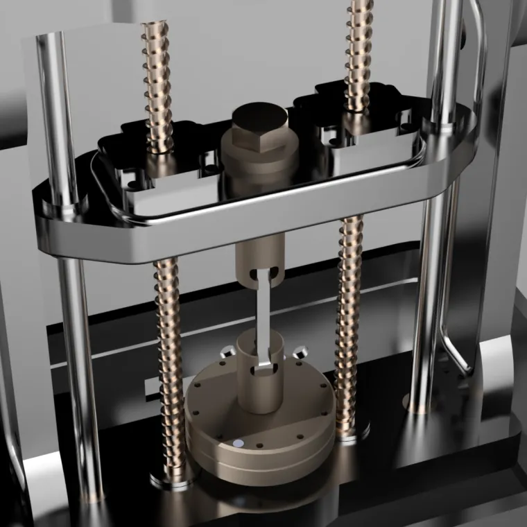
3. Movable Crosshead Assembly
The crosshead is an intricately designed component that travels vertically along the screw threads. Its polished metallic finish and contoured edges showcase careful machining. At the top of the crosshead, a large central nut or mechanical hub interfaces with the rotating screws, translating rotational input into linear motion.
The crosshead includes side brackets and machined slots for mounting additional fixtures or inserts, indicating modularity. Four counterbored socket screws secure the upper fixture plates, ensuring rigidity under loading conditions.
The entire crosshead assembly is built heavy and reinforced, minimizing flex and enabling the user to perform compression, tension, or bending tests reliably.
4. Load Application Mechanism
The heart of the machine is its manual load application system, powered by a hand-operated rotary wheel located on the right side. This large circular handle—machined with polished edges and evenly spaced spokes—provides leverage to rotate the screw shafts.
As the operator turns the wheel:
-
The screw rotates.
-
The crosshead travels downward or upward.
-
The specimen placed between the upper and lower fixtures is loaded in tension or compression.
The mechanical simplicity ensures minimal maintenance while maintaining good control over displacement and loading rate. The manual mechanism also allows the machine to be used in educational labs where slow, observable loading is desirable.
5. Specimen Holding Fixtures
At the lower section of the machine, there is a cylindrical compression/tension platform mounted at the center of the base. This platform includes multiple equally spaced threaded holes, enabling different jigs or attachments to be bolted on. The center hub is designed to hold the lower grip or fixture for tensile specimens.
From the upper crosshead, a vertical extension rod descends to connect with the upper fixture. This linkage appears robust and aligned precisely on the central axis, ensuring uniform load distribution.
The fixtures shown seem suitable for:
-
Compression tests (using flat platens)
-
Tension tests (using a clevis-like connection or wedge grips)
-
Possible shear testing with modified attachments
The model intentionally shows versatility, which is a hallmark of universal testing systems.
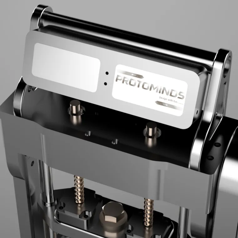
6. Branding and Aesthetic Details
A standout feature is the branding plate mounted at the top front. The name “PROTOMINDS” is beautifully engraved or embossed, accompanied by the tagline “Design with fun…” This branding plate is sandwiched between two thick, curved support plates, adding a signature look to the machine.
The metallic textures, including chrome, brushed steel, and bronze, give the model a premium appearance. Rounded corners, polished surfaces, and seamless transitions between components contribute to a highly refined industrial design.
7. Design Intent and Functionality
From the model’s construction, it is evident that the design follows key engineering principles:
-
Symmetry for uniform load application
-
Stiffness through reinforced beams and columns
-
Modularity for interchangeable fixtures
-
Accessibility for easy specimen mounting
-
Manual control ensuring slow, precise loading
This UTM design is ideal for laboratories, small workshops, or academic institutions that require a compact yet reliable testing system without the need for electronic actuators.
Conclusion
This Manual Universal Testing Machine model is a thoroughly detailed and visually impressive piece of mechanical design. It successfully integrates form and function, combining accuracy, structural integrity, and aesthetic refinement. The dual-screw crosshead mechanism, polished metallic surfaces, modular fixtures, and intuitive manual operation all reflect the skill and attention to detail put into its creation. Whether meant for demonstration, manufacturing, or academic usage, the machine stands as a robust example of precision engineering and thoughtful design execution.