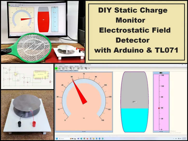

Story
A Static Charge Monitor also known as a Static Field Meter or Electrostatic Voltmeter is a device used to measure the presence and magnitude of static electricity (electrostatic charges) on surfaces, objects, or in the surrounding environment. Generally this type of instruments are divided into Contact-Based Meters wich Measure charge by direct contact with a surface and Non-Contact (Field Meters) that Use electrostatic induction to measure charge from a distance. Another division is based on the duration of the measurement, namely momentary checks in different locations and Continuous 24/7 Monitoring Systems.
Detailed video instructions at: https://youtu.be/tbTLgHMtbKU
In this project I’ll present a circuit design for a continuous static charge monitor that you can build or adapt. This design focuses on non-contact electrostatic field sensing, real-time voltage measurement, and output signaling.
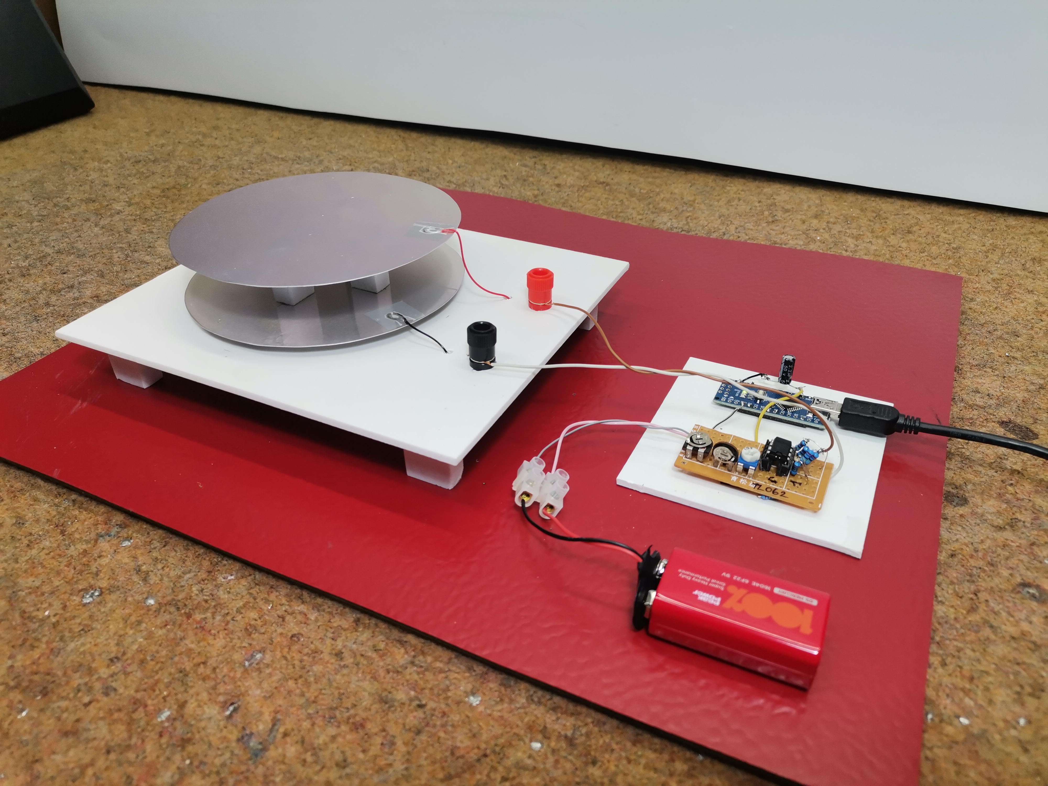
The device consists of three basic parts: a detector, an electronic part, and a unit for displaying and logging the result. Now I will explain each part individually.
- First of all, about the detector, it can be said that this is the most important part, considering that it is used to detect and receive the static charge. It consists of two metal plates placed parallel at a certain distance and insulated from each other. The sensitivity of the detector is directly proportional to the surface area of the electrodes and inversely proportional to their distance. This means that the larger the surface area, and the smaller their distance from each other, the greater the sensitivity.
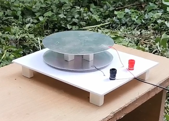
This time I will not go into further detailed analysis of the method of creating and manufacturing the sensor, I will just tell you that based on the many tests I have done previously, this is a certain compromise between the sensitivity and stability, accuracy and practicality of the sensor. Specifically, the surface area of each of the electrodes is about 115 cm2 (diameter is 6cm), and their distance from each other is 2.5 cm. Also, their shape is not chosen randomly and it has a circular shape, in order to reduce the so-called "leakage" effect. This is the simplest type of electrostatic charge detector and responds best to changes in electrostatic charge over time, which practically means that the charged object has to be moved close to the detector as we will see later in the demonstration. This is not practical in the case of measuring an Atmospheric Charge Monitor, where a Field Mill detector is used which uses rotating or vibrating conductive plates and generates an AC signal whose amplitude is proportional to the field strength.
- The next part of the device is a relatively simple electronic circuit consisting of an OPAMP JFET IC TL071 which functions as a comparator and amplifier of the signal generated by the detector.
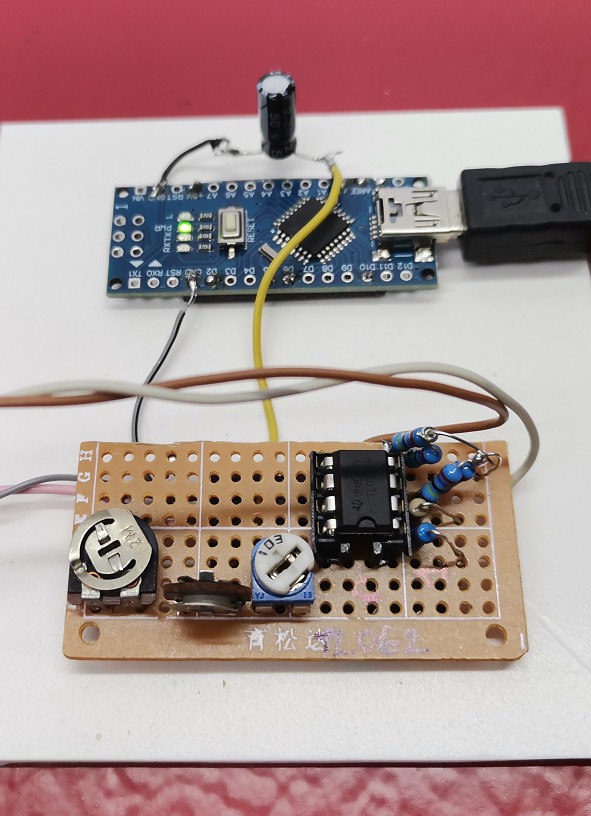
To briefly explain the adjustment method, we place the potentiometer P1 in the far left position (that is, a resistance close to the maximum), and P3 in the middle. We connect a voltmeter to the middle terminal of P3 and move the potentiometer P2 until the voltmeter reads 0 volts. At that moment, the detector is most sensitive and now with the potentiometer P3 we can adjust the range in which the voltage that we bring to the microcontroller will move. Now we bring the signal to the microcontroller, in this case Arduino nano which has the function of processing this signal and sending it to the PC software where we can visually monitor the values and changes. For this circuit you need to upload the given simple code in a way that has been explained many times before. For those DIYers who have no experience with microcontrollers, I can say that instead of a microcontroller, a digital voltmeter can be directly connected to the output of this part with an OPAMP, or even better an analog instrument with a moving needle, which gives us a complete device that also has certain advantages in the sense that we can make it in a portable version.
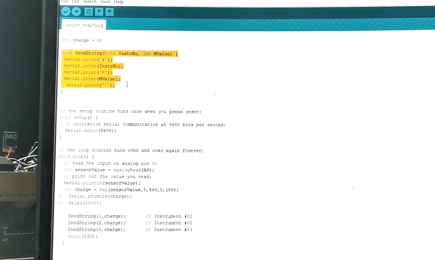
Just a few simple notes about the Arduino code. This is the string that is sent at the beginning and serves as a signal for the Windows application to accept the data sent by the Arduino. Then the baud rate is set to 9600 and finally we can experiment with these two values depending on the level of the detected signal and the position of the potentiometer P3. At the end of the code, values are sent to the three instruments that we will define in the Windows application.
And as I mentioned at the beginning, for visual presentation of the results I use a PC with the wonderful Windows application "Serrialcominstruments" installed, which is the work of Ulrich Albert Maassen and you can download the latest version 4.1 on the given page (https://www.mikrocontroller.net/topic/310940?page=6), and use it freely but only for personal needs. In fact, this time I will only briefly explain how to set up the program specifically for this case. I am trying to get in touch with the author, and if I get his permission, I plan to make a video with more detailed instructions on setting up and using this really useful tool.
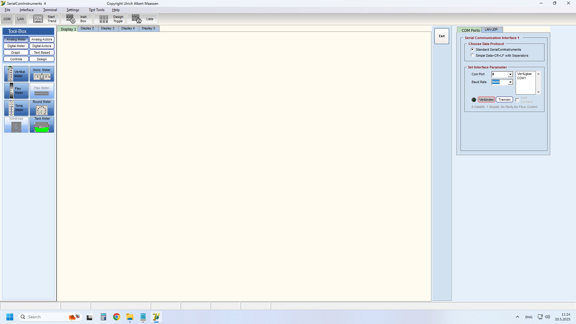
First, we go to INTERFACE, then select the COM port that corresponds to that of the Arduino, and select the baud rate 9600 and press CONNECT, then EDIT. Then INSTRUMENT BOX and select the three instruments that we will use (round meter, tank and vertical meter. Now we go to DESIGN TOGGLE and set the colors and range of the three instruments by double-clicking on each one individually. Next, we press START TREND and the testing and measurement can begin.
For this purpose, I can create an electrostatic charge on a plastic ruler through a process called triboelectric charging, which involves rubbing them with certain materials, in this case a woolen cloth. First, I will test the presence of a charge on small light pieces of paper that will be attracted under the action of the charge.
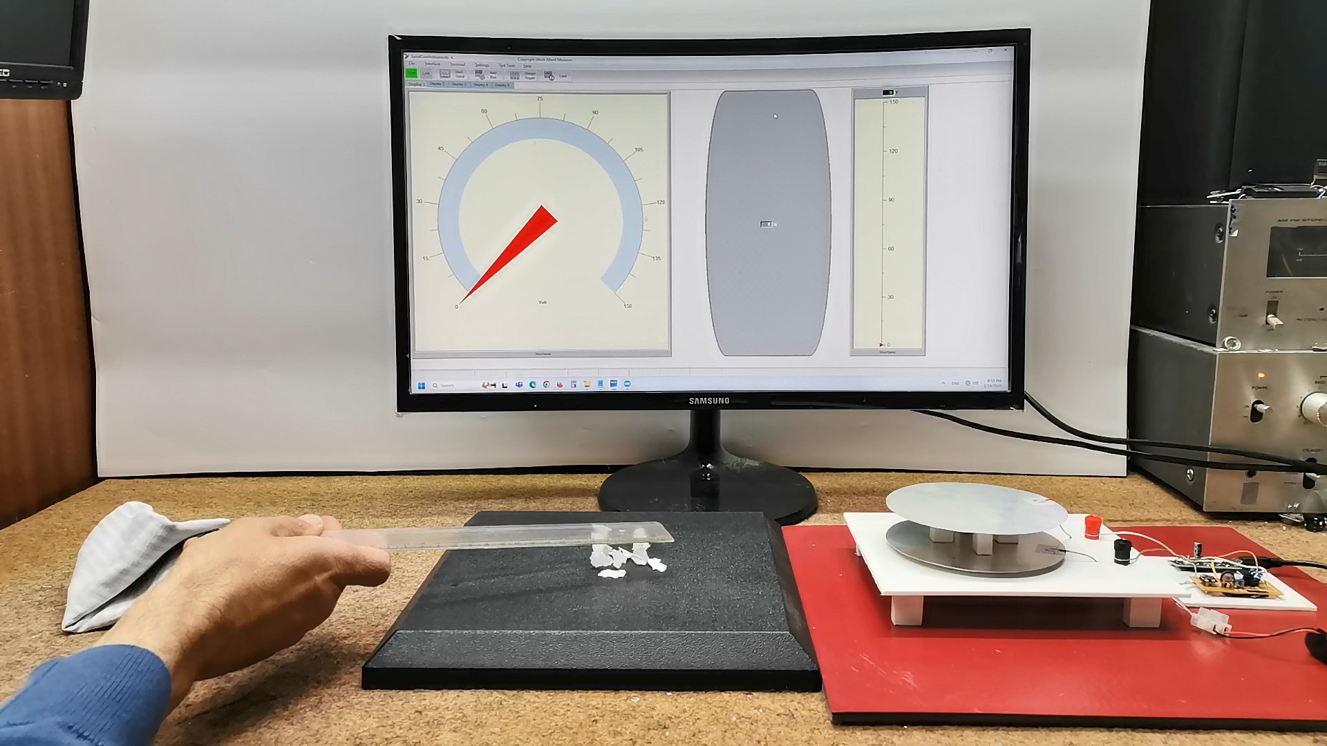
Now let's test the functionality of the device whose construction I have presented so far. As I mentioned at the beginning, with this type of detector, it is necessary to move the object (the ruler) over the plates if we want to instantly detect the charge. The instruments in the application show a momentary large deflection, which is a sign of the presence of a charge near the detector plates. Otherwise, this type of detector reacts equally to positive and negative charges. Now I will show you a special case of continuous monitoring of static charge generated by this mosquito killer in the form of a tennis racket. By pressing the button, a high-voltage electrostatic field is generated and under the influence of this field, the capacitor is charged, which consists of metal grids placed at a certain distance. If we connect the electrodes of the capacitor, it will discharge, generating a high-voltage spark.
Now, on the instruments in the application, we see a very interesting case.
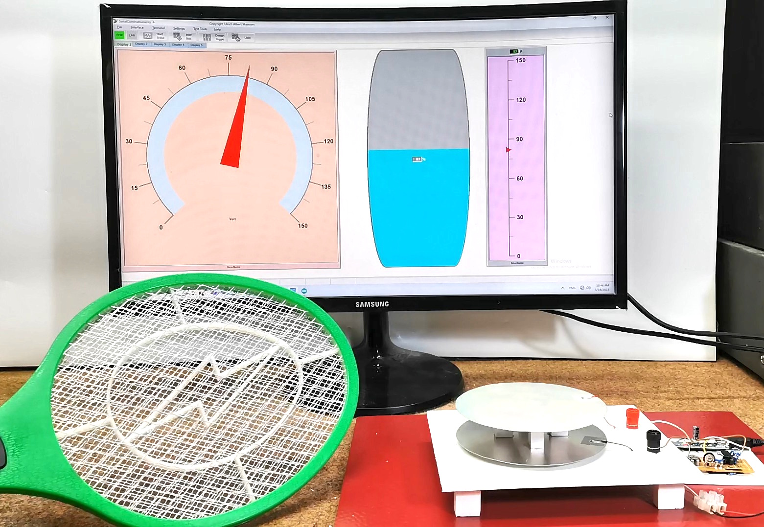
Namely, the strength of the static charge changes continuously depending on the distance between the source and the plates, and even if the source is not moving, the instruments display the current value continuously. In fact, this is a feature only of the so-called Field Mill detectors. Now I will explain why this is so in this special case. The way this mosquito killer works is as follows. First we have a source of alternating signal. Then through a power mosfet this signal is carried to the primary of the HV transformer on whose secondary an alternating high voltage is generated. Then this voltage is rectified with a diode and a capacitor.
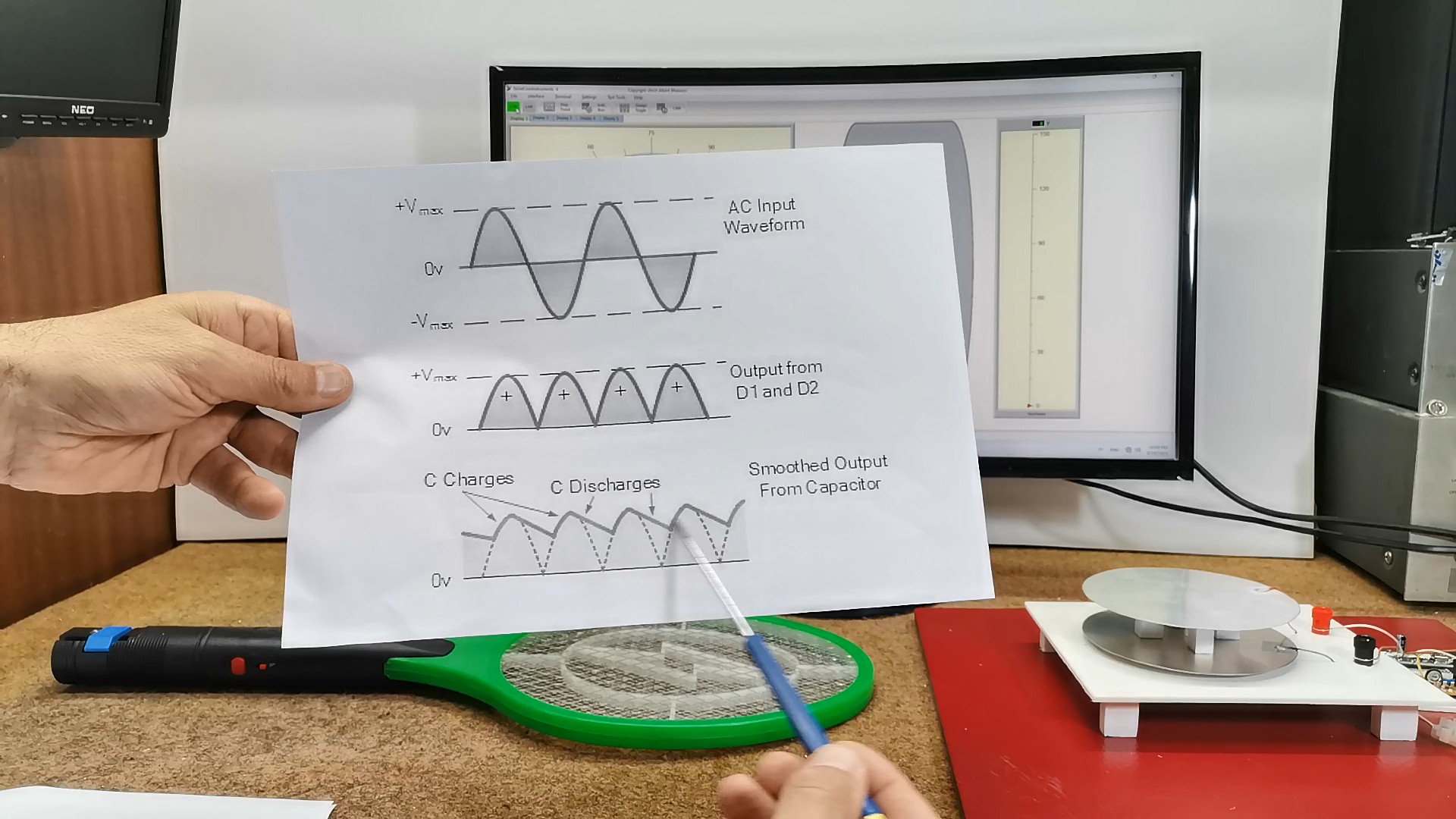
The final voltage which generates the electrostatic field and which charges the signals has the following form, so it is not ideally straight. So our detector detects these small fluctuations of the direct voltage, and these small changes simulate constant movement (vibration) of this source of static charge.
I would like to remind you that this is not a professional device and the values you read on the application are only empirical numbers, so we need to have a commercially calibrated device for comparison and accurate marking of the scale.
And finally, a brief conclusion. This simple Static Charge Monitor uses a parallel-plate detector and TL071 op-amp circuit to measure electrostatic fields, with real-time visualization via Arduino and PC software. Although it is not a professional device, it is an excellent educational tool for studying the properties of static electricity.