Story
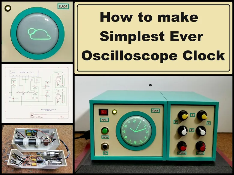
An oscilloscope clock is a unique and creative way to display the time using an oscilloscope, which is a test and measurement instrument typically used to visualize and analyze electronic signals. In one of my previous videos I presented you a way to make the simplest oscilloscope with a small 2 inch CRT tube. This time I will describe to you also a very simple way how to make a Oscilloscope Clock with the same CRT tube. There are several projects of this type on the Internet, but they are relatively complex for self-construction, so I decided to make an Oscilloscope clock in the simplest possible way. It even avoids the use of a mains transformer which is expensive and difficult to obtain, and initially the device works on 12V. But despite its simplicity, it is fully functional, highly adjustable, and has the option of automatically setting the time via the Internet. So it even outperforms more complex devices of this class.
Detailed video instructions at: https://youtu.be/s0NppvGP4bw
Basically the device consists of two parts, and one is a signal generator usually made with the help of a microcontroller, and the other part is an X-Y mode oscilloscope that visualizes this signal in the form of an analog clock.
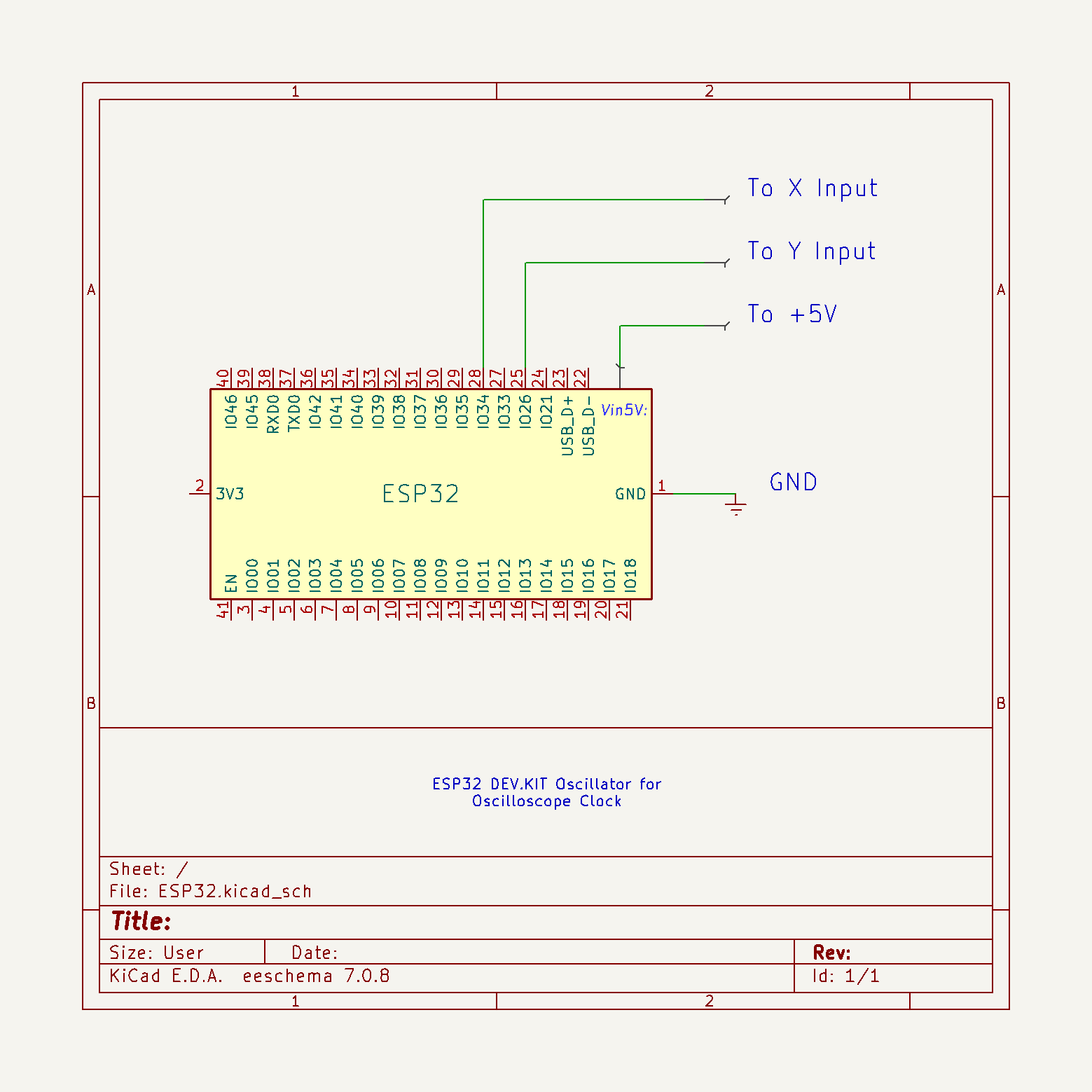
First I will focus on the signal generation part. It is extremely simple and uses only an ESP32 Microcontroller board without any external components.
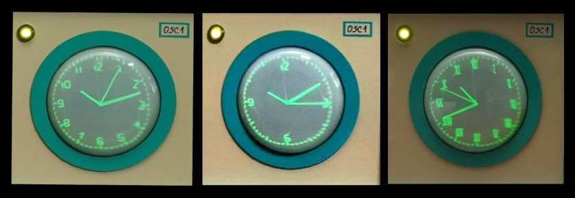
The code is the work of Mauro Pintus (https://github.com/maurohh/ESP32_OscilloscopeClock), and I just made a small modification, so now with a button we can choose between a clock with standard or Roman numerals. If you enter the data of your local Wi-Fi network in the code, the time will be updated automatically via the Internet, and if you do not have the Internet, the initial time that will appear when the clock starts can also be adjusted in the code in the (given) lines:
int h=10; //Start Hour
int m=8; //Start Minutes
int s=37; //Start Seconds
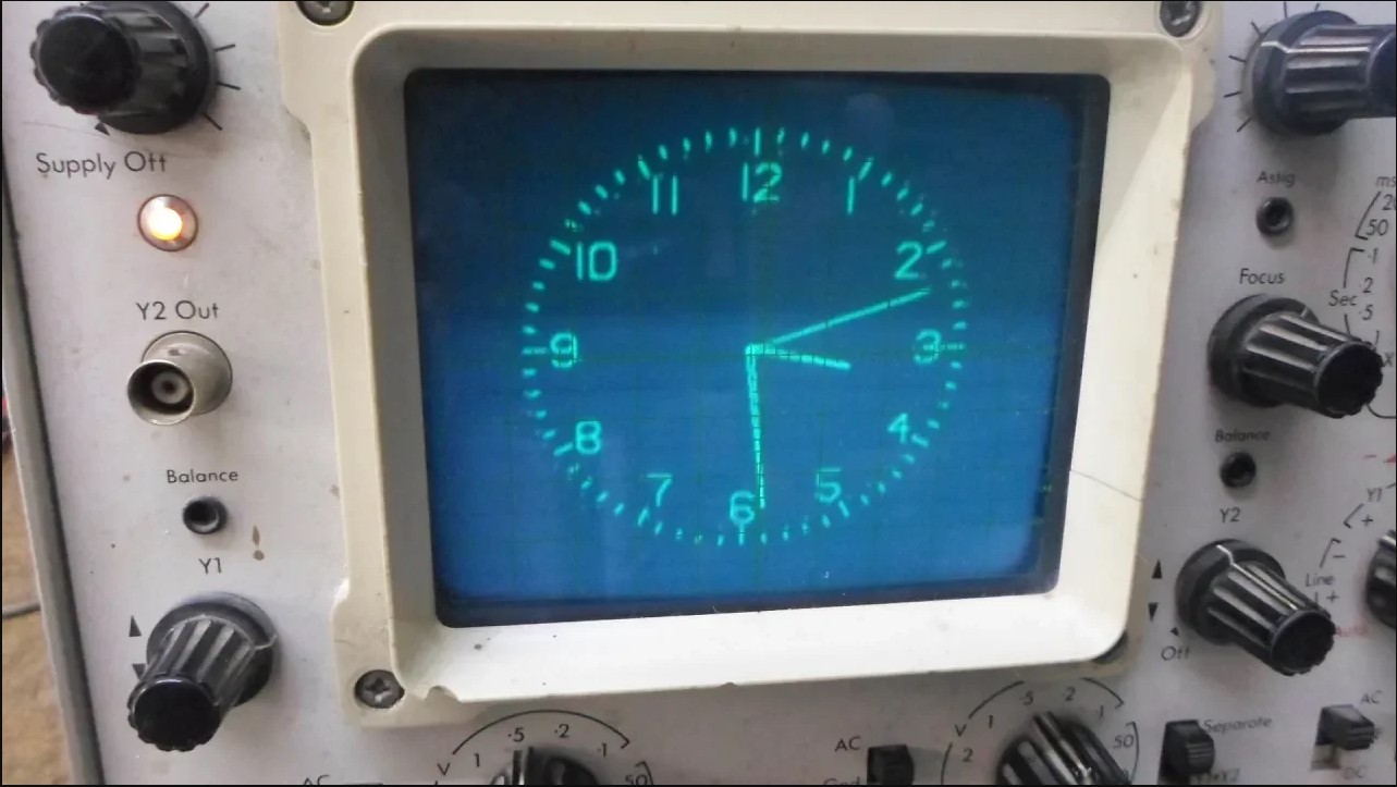
Otherwise, I successfully tested a version of the code where the time is set manually through three buttons, but for the sake of simplicity, I left this version out. This time I will not dwell on the installation of the code on ESP32 , as it is described in many detailed tutorials that you can find on the Internet. Regarding the connection method, pin 25 of ESP32 should be connected to X Input, and pin 26 to Y Input of oscilloscope. The ground from the microcontroller is connected to the ground from the scope. Also in one of my older videos you can see how this clock works on a commercial Oscilloscope.
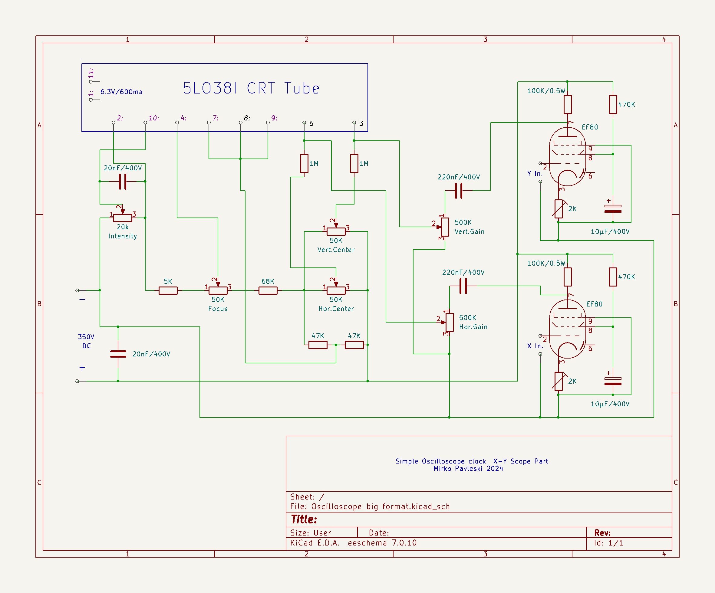
Next, I will briefly describe the method of making the X-Y mode oscilloscope. As I mentioned before, the device has a complete control of the position and size of the image, which is done with the help of four potentiometers, and there are also potentiometers for adjusting the intensity of the light as well as for focusing the image.
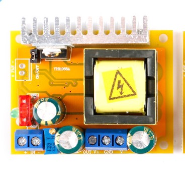
As in my previous oscilloscope project, I will also use an inexpensive DC-DC step-up for power supply, where with an input voltage of 12V, the output voltage can be continuously adjusted within the range of 45 to 390 volts
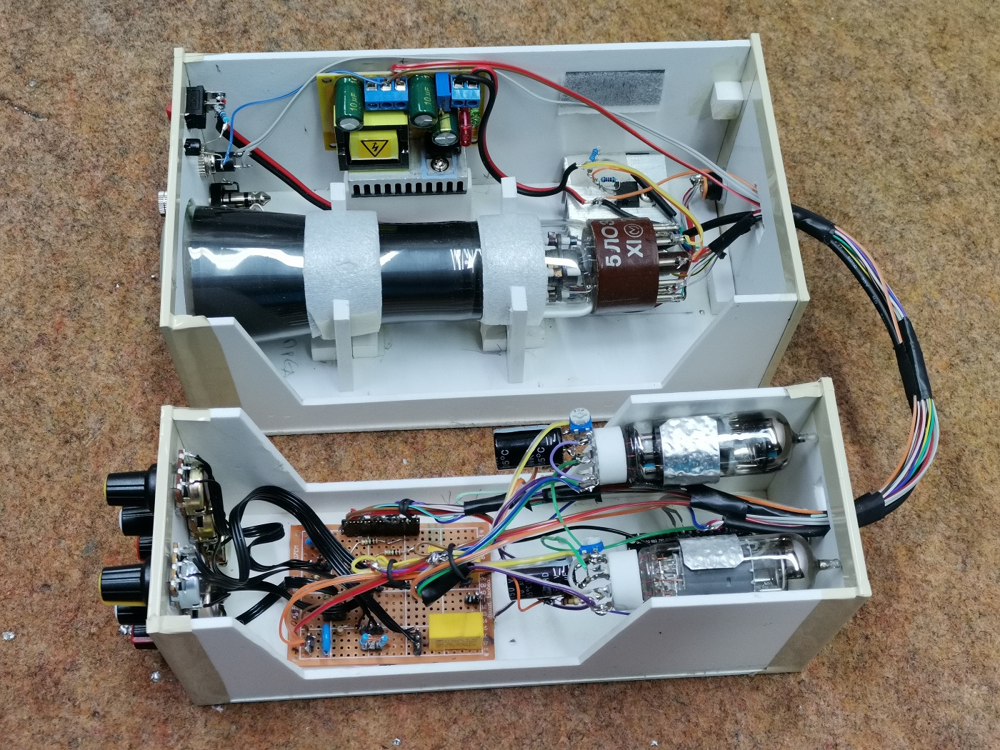
So the complete device consists of the following components:
- 2 Inch CRT display type 5LO38I
- Step Up Power supply module 12V to 300V
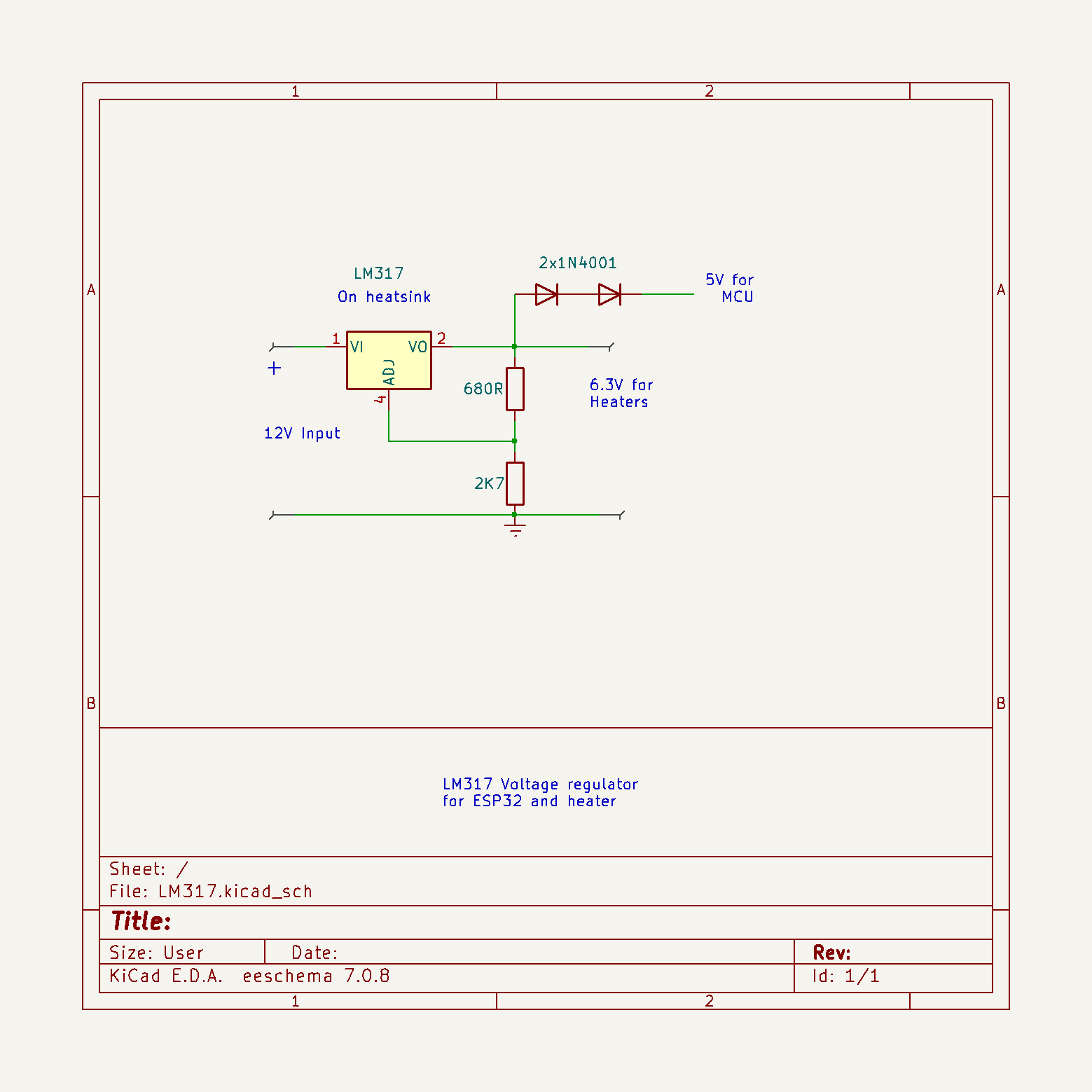
- LM317 voltage regulator with which we get a voltage of 6.3V for heating the tubes
- Two EF80 tubes as horisontal and vertical deflection amplifiers
- Six control potentiometers
- "Mode" button
- several passive elements, resistors and capacitors,
- and ESP32 microcontroller board
At the input of the boost converter we bring 12V, which then increases to 350V. The output voltage can be precisely adjusted with this multiturn potentiometer. This high voltage serves to power the CRT display and the tubes. An input of LM317 voltage regulator is connected to the 12V , the output of which produces 6.3 volts used for heating the three tubes. Since the heating current reaches a value greater than 1A, the regulator must be mounted on an aluminum heatsink. I got the necessary 5V for powering the ESP32 microcontroller by connecting two diodes in series to the 6.3V output, which gives exactly 5V due to the voltage drop of the two diodes.
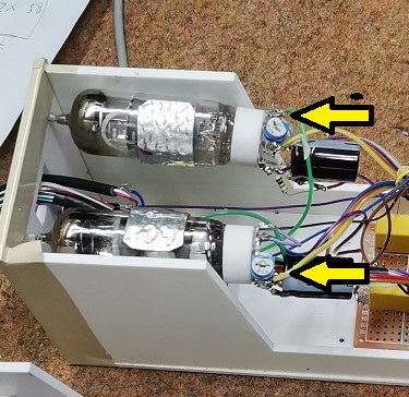
In fact, the basic idea of simplicity of the device required the use of a single power supply for all the components, and at the same time, it should be performed in a simple way. That's why this part of the project took me the most time.The two EF80 vacuum tubes are actually horizontal and vertical deflection amplifiers. Initially, I wanted to use MPSA45 NPN transistors for this purpose, but during a random mistake, they burned out and I didn't have any spares, so I decided to continue with vacuum tubes. But these tubes were used for a long time in old devices, so they had different characteristics, so instead of a fixed resistor, I placed trimmer potentiometers on the cathodes, with which I can adjust the clock circle as precisely as possible.
And now let's see how the device works in real conditions. After switching on, a certain time should pass for the cathodes of the tubes to heat up, and an image to appear on the CRT screen. During this time, the ESP32 updates the correct time if the Wi-Fi credentials are entered in the code, and so the clock starts working. Let's see how the picture adjustment potentiometers react.
And now let's see how the device works in real conditions. After switching on, a certain time should pass for the cathodes of the tubes to heat up, and an image to appear on the CRT screen. During this time, the ESP32 updates the correct time if the Wi-Fi credentials are entered in the code, and so the clock starts working. Let's see how the picture adjustment potentiometers react.
And now let's see how the device works in real conditions. After switching on, a certain time should pass for the cathodes of the tubes to heat up, and an image to appear on the CRT screen. During this time, the ESP32 updates the correct time if the Wi-Fi credentials are entered in the code, and so the clock starts working. Let's see how the picture adjustment potentiometers react.
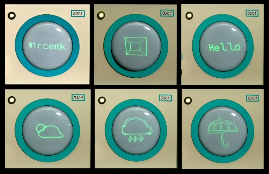
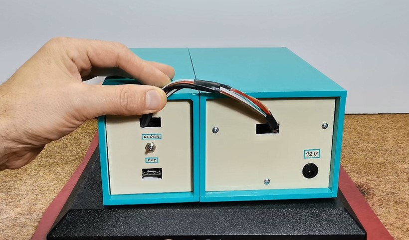
There are several PC Applications, which generate a signal on the sound card which is then converted into an image or text. For this purpose I have installed a switch on the back side through which we can choose the type of input signal between the MCU Clock, or an external signal source, in this case a PC sound card.
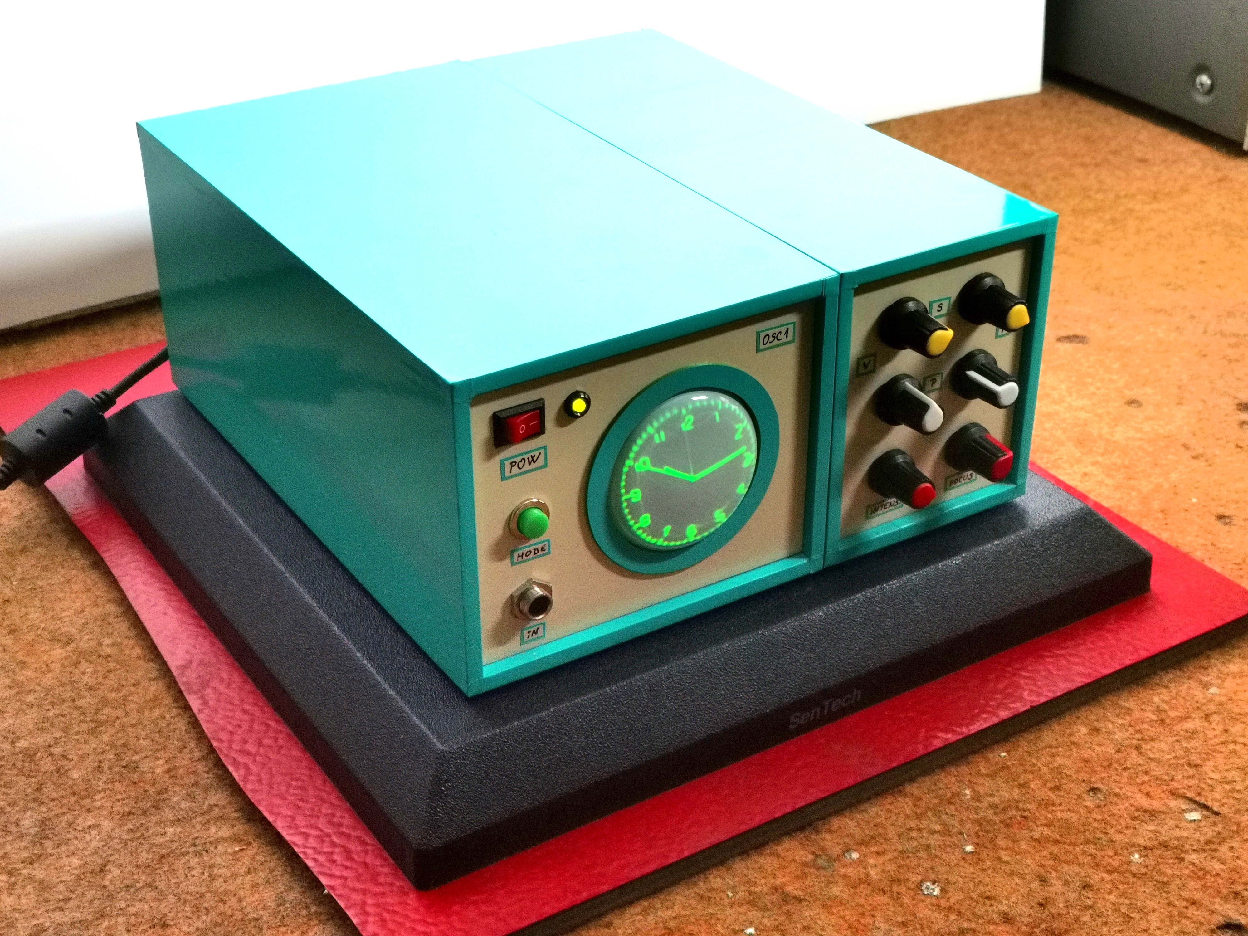
The device is installed in a suitable box made of PVC material with a thickness of 5 mm, and covered with colored self-adhesive wallpaper.
And finally a short conclusion:
Building an oscilloscope clock can be a very fun and educational electronics project. It combines aspects of programming, circuit design, and creativity. But we should keep in mind that this clock is almost unreadable in daylight, which is a characteristic of the CRT display itself, so those beautiful pictures of such devices that you see on the Internet are actually taken in a partially darkened environment. However, it is a great pleasure, especially for the younger generations of self-builders, to make such a retro clock, bearing in mind that for a relatively low price, remaining supplies of CRT screens and vacuum tubes can be obtained on internet.
SAFETY NOTE: Please do not attempt to recreate the experiments shown on this video unless you are familiar with High Voltage Safety Techniques! Direct Current even above 60V maybe lethal, even when the AC supply voltage has been disconnected due to the stored energy in the capacitors. I have no responsibility on any hazards caused by the circuit. Be very careful. This is a humble request.