


Story
Special rs232 cable for the Tandy Portable Disk Drive aka Brother FB-100 aka KnitKing FDD19
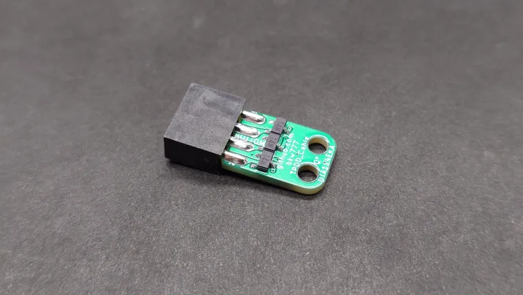
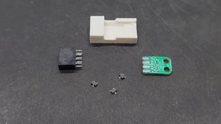
The cable needs to translate between rs-232 and ttl, and needs a special plug shape on one end.
The circuit here, using 3 internally biased transistors, relying on pullup resistors in the Model 100 computer to do part of the job, is the same as in the original cable from Tandy that shipped with the drive.
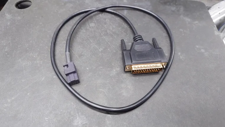
You also need the 3D printed plug housing and a generic serial "modem" cable with a factory molded DB25 male connector on one end. Don't make your own db25 cable end with a typical db25 backshell that you assmble yourself. That type of backshell doesn't fit all the way into the serial port on a Model 100 (or any of the clones). The backshell housing interferes with the computer case and prevents the db25 from inserting all the way. It still makes a connection just not very good. A molded cable inserts all the way.
Wiring and building directions are in the main readme on github.
https://github.com/bkw777/TPDD_Cable
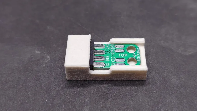
The 3d printed soldering jig is not for the wires or transistors. It's just for holding the pcb aligned straight & level while floating between the two rows of pins on the 2x4 connector.
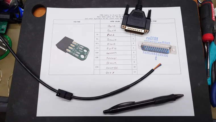
Print the wire-colors worksheet. Cut the cable in half if you want to make both a Model 100 cable and a WP-2/PC cable, or just cut off the DE9 plug to make a single longer Model 100 cable. Cut and strip all the wires. Don't install heat-shrink yet. Put a DMM in continuity mode and attach an alligator clip jumper to one probe. Pick any wire and clip the alligator probe to it. Use the other probe to find which pin on the DB25 beeps. Write the wire color for that pin number in the table. Repeat for all wires.
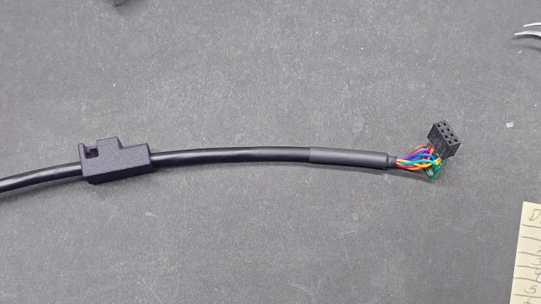
Slide the 3d-printed plug housing onto the cable and move several inches back from the end. Slide the heat-shrink onto the cable but do not shrink it.
Solder the wires to the pcb by matching the signal names like "TX" on the worksheet to the TX pad on the PCB. Cut the unused wires short.
Slide the heat-shrink into place and shrink it. Slide the plug housing into place. The flat side of the housing is the bottom. The trasistors face down and the wires are on top. Push the pcb into the housing, don't pull on the cable!
Optionally add glue into the wire cavity inside the housing at this point or at any point after this.
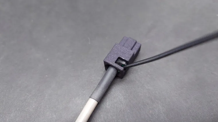
When the pcb is all the way in, push the cable in as far as possible, wigglling and rotating a little to get it as far in as possible.
Insert a 4mm zip-tie pointing straight down next to the cable, with the smooth side out, teeth facing the cable. Push down until the cable tip comes out the top of the housing. Pull the rest of the zip-tie most of the way with pliers, thread through the eye, shove the cable in tight again and cinche the zip-tie down the rest of the way with pliers. Tug the zip-tie both clockwize and counter-clockwise around the cable to ensure it doesn't snag on the edges of the pcb holes and tightens all the way down.