


Story
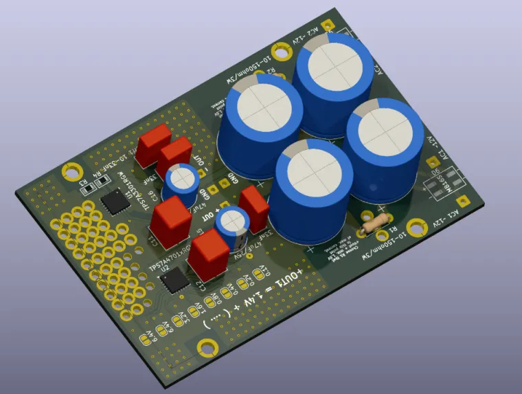
Low Noise Adjustable ± Audio Power Supply based on TPS7A47xx / TPS7A33xx
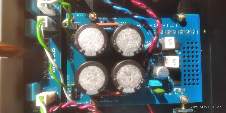
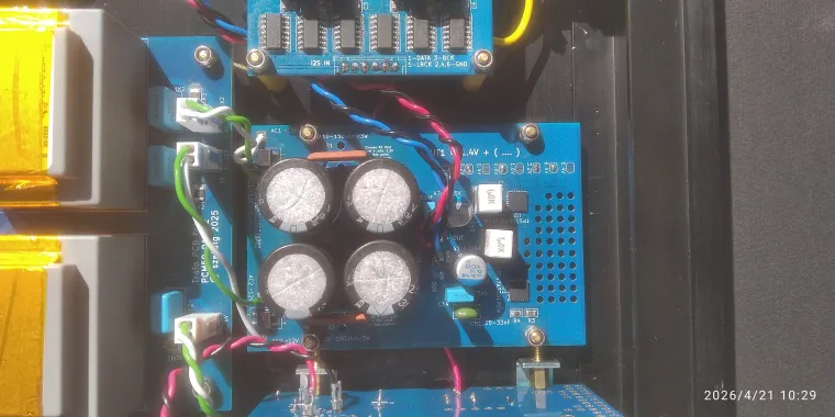
This project is a low-noise dual-rail linear power supply intended for audio applications, precision analog stages, DAC analog rails, I/V sections, output buffers and other circuits that benefit from very clean and stable ± DC rails.
The design is based on two high-performance LDO regulators from Texas Instruments:
- TPS7A4701 for the positive rail
- TPS7A3301 for the negative rail
Main features
- Low-noise regulated positive and negative output rails
- Adjustable output voltage for both rails
- Designed for audio and precision analog use
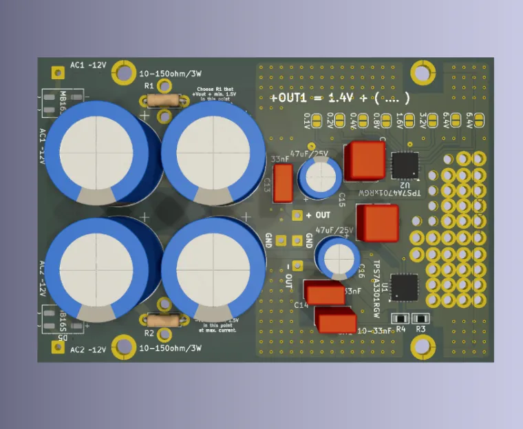
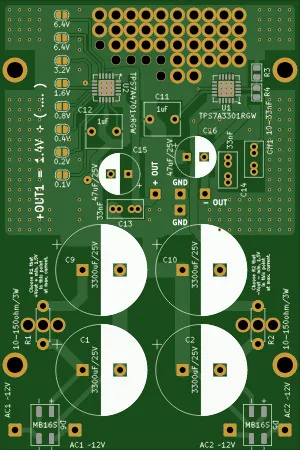
- Rectifier stage with dual Schottky bridge rectifiers
- Post-rectifier C-R-C filtering before the LDOs
- Practical output current up to about 0.8 A, depending on input/output voltage difference, heatsinking and PCB thermal conditions
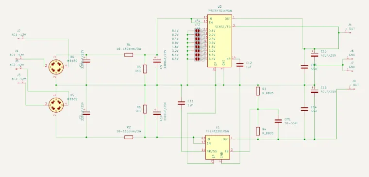
Why two bridge rectifiers?
The PSU uses two separate Graetz bridges built with Schottky diodes, one for the positive side and one for the negative side. This helps avoid the “floating ground” problem that can appear with transformers having imperfectly matched secondary voltages. If the two AC windings do not deliver exactly the same voltage, the separate rectification arrangement keeps the center reference much more predictable and suitable for audio use.
Input filtering
After rectification, each rail is filtered with a C-R-C network. In the schematic this is implemented with the large reservoir capacitors and series resistors before the regulators. The C-R-C stage reduces rectifier ripple and high-frequency trash before it reaches the LDOs, allowing the TPS7A devices to work in better conditions and deliver cleaner output rails.
Positive output voltage setting
The positive rail is generated by TPS7A4701 used in ANY-OUT mode. The output voltage is selected by solder jumpers on the PCB, marked directly on the board. The base voltage is 1.4 V, and the final output voltage is the sum of 1.4 V plus the active jumper values.
Positive rail formula:
Vout(+) = 1.4 V + selected jumper values
Available jumper values on the PCB are:
- 0.1 V
- 0.2 V
- 0.4 V
- 0.8 V
- 1.6 V
- 3.2 V
- 6.4 V
- 6.4 V
This gives programmable positive output voltages from 1.4 V up to 20.5 V in 100 mV steps.
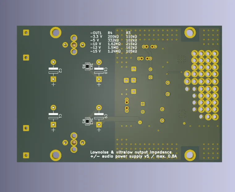
Negative output voltage setting
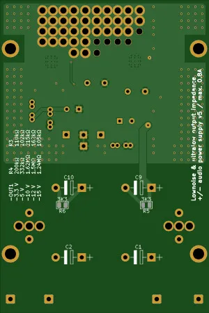
The negative rail is generated by TPS7A3301. On this PCB the negative output voltage is set with the feedback divider formed by R4 and R3 near the regulator.
- R4 = resistor from -OUT to FB
- R3 = resistor from FB to GND
This resistor order matches the reminder table printed on the bottom silkscreen of the PCB. The board marking is:
-OUT1 | R4 | R3
Recommended resistor values for TPS7A3301
(verified against the PCB reminder table and aligned with the datasheet values)
| -OUT1 | R4 | R3 |
| -3.3 V | 200 kΩ | 110 kΩ |
| -5 V | 332 kΩ | 102 kΩ |
| -10 V | 1.62 MΩ | 215 kΩ |
| -12 V | 1.5 MΩ | 162 kΩ |
| -15 V | 1.24 MΩ | 105 kΩ |
These are the values shown on the PCB as a quick reminder. Use precision resistors if output accuracy matters.
Expected noise performance
- Positive rail (TPS7A4701): typically around 4.17 µVrms at 1.4 V, 4.67 µVrms at 5 V, 7.25 µVrms at 10 V, and 12.28 µVrms at 15 V, measured over 10 Hz to 100 kHz with the recommended capacitor arrangement.
- Negative rail (TPS7A3301): typically about 16 µVrms over 10 Hz to 100 kHz with the recommended capacitor arrangement.
In practice, the positive rail is exceptionally quiet, while the negative rail is still very low-noise and well suited for audio analog supply duties.
Practical notes
- The board is intended for clean analog/audio power, not for highest efficiency.
- Maximum real-world current depends strongly on dropout voltage and heat dissipation.
- For best results, choose transformer voltage that leaves enough regulator headroom, but does not create excessive heat in the LDOs.
- The bottom silkscreen also includes a reminder to choose the CRC resistors so that enough input headroom remains at maximum current.
Applications
- DAC analog rails
- I/V converter stages
- Op-amp analog supplies
- Headphone amplifier front-end rails
- Low-noise analog experiments
- Precision audio circuits requiring regulated ± supply
The BOM file is configured for ±12V.


