










Story
Parametric 3D-Printed Electronics Enclosure Generator
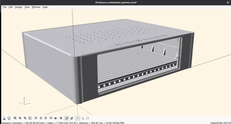
Short description: An OpenSCAD generator for creating fully customizable, professional-looking 3D-printed electronics enclosures with slide-in PCB or acrylic front and rear panels, configurable ventilation, and a hidden internal PCB mounting system.
Project Introduction
This project is a parametric OpenSCAD generator for two-part electronics enclosures. Instead of redesigning a case from the beginning for every device, you can change a set of clearly described parameters and generate a new top and bottom enclosure ready for 3D printing.
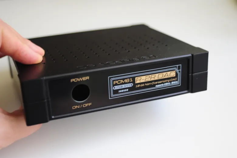
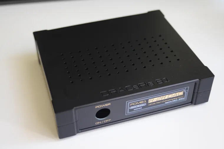
The enclosure is designed for electronic instruments, controllers, power supplies, audio devices, test equipment, IoT projects, prototypes, and other custom electronics. The generated model combines practical internal mounting features with a clean external appearance.
Professional Front and Rear Panels
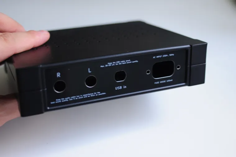
The front and rear panels slide into dedicated channels in the enclosure. They can be manufactured from standard FR-4 PCB laminate, acrylic, or another suitable sheet material.
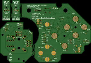
Using PCB laminate for the panels makes it possible to add professional silkscreen labels, symbols, connector descriptions, logos, scales, and other graphics directly during PCB production. Connector cutouts and mounting details can be designed in a PCB CAD tool, while the printed enclosure provides the surrounding mechanical structure.
The panel width, height, thickness, channel clearance, visible opening, side capture, edge lips, corner radius, and external bevel can all be adjusted. The default panel-slot clearance is linked to panel thickness to provide a close sliding fit.
Hidden PCB Mounting
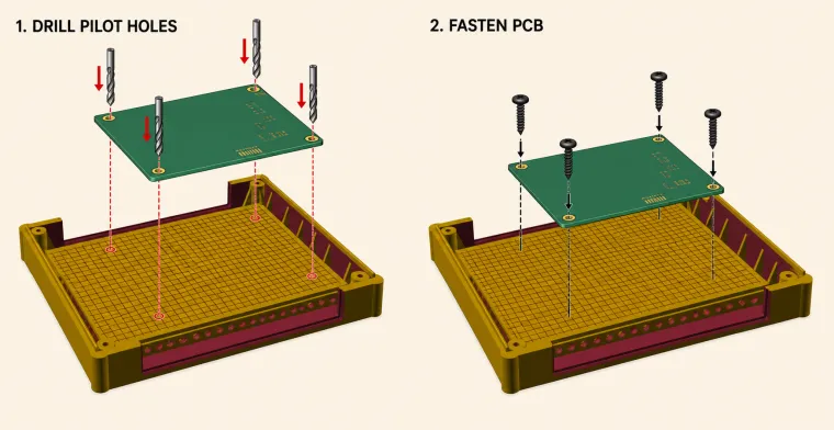
The bottom half contains a raised internal PCB mounting platform positioned above the enclosure floor. The board is placed on this platform, its mounting-hole positions are marked, and pilot holes are drilled into the plastic. The PCB is then fastened from above with self-tapping screws for plastic.
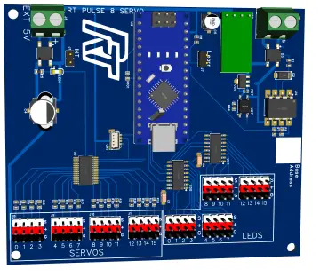
The PCB mounting screws remain inside the closed enclosure, so no PCB fasteners are visible on the outside. This gives the finished device a cleaner and more professional appearance. The elevated platform also separates the electronics from the external bottom surface and can be reinforced with ribs. ( please see the picture above )
- Place the PCB on the raised platform.
- Mark the PCB mounting-hole locations.
- Remove the PCB and drill suitable pilot holes into the platform.
- Return the PCB to the platform.
- Fasten the PCB from above using self-tapping screws for plastic.
Main Customizable Features
- External dimensions: enclosure width, length, and total height.
- Two-part construction: bottom-half height, top-half height, floor thickness, and roof thickness.
- Front and rear panels: panel width, height, thickness, fit clearance, channel lips, visible opening, edge capture, corner radius, and bevel.
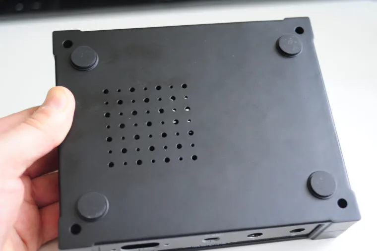
- Top ventilation: enable or disable the grille; configure hole diameter, rows, columns, pitch, margins, offset, and an optional alternate checkerboard hole size.
- Bottom ventilation: an independent grille with its own hole size, rows, columns, pitch, margins, offset, and alternate-hole settings.
- Enclosure assembly bosses: screw pilot diameter, clearance diameter, counterbore size, boss diameter, and boss positions.
- Structural reinforcement: optional ribs for screw bosses and long side walls, including rib thickness, length, count, spacing, height, embed depth, and collision clearances.
- Bottom feet: enable or disable four ring-shaped feet and configure their diameter, hollow center, height, and X/Y spacing from the enclosure edges.
- External appearance: rounded-corner radius, edge chamfer, external corner cylinders, and surface smoothness.
- Top-cover marking: optional embossed or engraved text with configurable content, font, size, height, position, rotation, and alignment.
- PCB mounting platform: enable or disable the platform and configure its elevation, thickness, wall margins, and perimeter frame.
- Platform surface: choose a solid platform with an engraved guide grid or a perforated platform with a configurable hole pattern.
- Platform reinforcement: configure support-rib dimensions, rib counts, and ventilation holes in the long support ribs.
- Top and bottom alignment: tongue-and-groove depth, height, assembly clearance, and entry chamfer.
Why Use This Generator?
- One verified generator can produce many enclosure sizes and configurations.
- The most important settings are collected in one clearly documented parameter file.
- The mechanical generator code is separated from the user customization parameters.
- PCB-laminate panels can combine mechanical cutouts with high-quality printed labels.
- Internal PCB screws are hidden after assembly.
- Independent top and bottom ventilation can be adapted to the heat generated by the electronics.
- Reinforcement ribs, feet, bosses, and platform supports can be adapted to the printer, material, and application.
- Both enclosure halves can be exported as production-ready STL files.
How to Customize the Enclosure
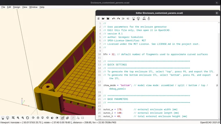
To use and change the scad file you need to install OpenSCAD software and change the parameters in editor.
F5 key in OpenSCAD give you a quick review of your changes.
Open Enclosure_customized_params.scad in OpenSCAD and edit the required variables. The file includes the generator implementation from _CODE_.scad, which normally does not need to be modified.
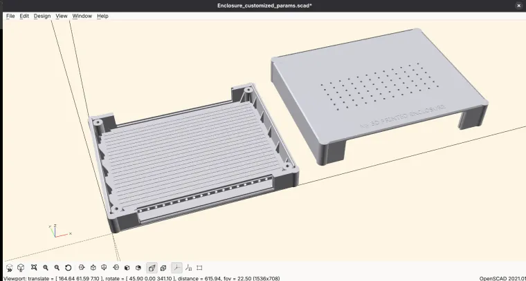
The show_mode variable selects the required view:
assembled- complete assembled preview.split- separated top and bottom preview.bottom- bottom printable part only.top- top printable part only.debug_panels- panel-fit diagnostic view.
Generating the STL Files
To export manually, set show_mode to top, perform a full F6 render, and export the result as STL. Then set show_mode to bottom, perform another F6 render, and export the second STL.
The project also includes generate_final_STL_for_3D_print.sh. On Linux, this script renders the top and bottom production STL files in parallel and stores them in the TO_production directory.
Manufacturing Options
- 3D print the top and bottom enclosure halves.
- Manufacture the front and rear panels as FR-4 PCBs with silkscreen descriptions and accurately placed cutouts.
- Alternatively, laser-cut the panels from acrylic or another flat material.
- Drill the internal mounting platform to match the actual PCB mounting holes.
Open Source License
The generator is released under the MIT License. You can use, study, modify, and redistribute it according to the license terms included with the project.