Story
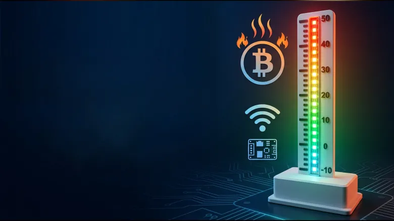
Summer has been relentless this year. My passion for Bitcoin mining took a major hit due to the immense heat from my miners and the electricity costs required to keep them cool and running. There were times when the miners overheated so badly that I had to shut them down "manually" to prevent a fire hazard.
To automate the shutdown and restart process and to enable remote temperature monitoring, I built an RGB thermometer with its own web interface that can control home appliances based on temperature changes.
Watch this video, for detailed step by step instructions on how to build this circuit and to know how this circuit works.
Video: https://www.youtube.com/watch?v=WecOhmHxspg
Components Required

For this project we need:
1 x ESP32-C3 Super Mini : https://s.click.aliexpress.com/e/_omnke4z
1 x WS2812B RGB LED Strip : https://s.click.aliexpress.com/e/_c4oOdHi9
1 x DS18B20 Temperature Sensor : https://s.click.aliexpress.com/e/_c3oKzGsz
1 x 4.7K Ohm Resistor : https://s.click.aliexpress.com/e/_c3jMGVWl
Upto 6 Optional Relay Modules : https://s.click.aliexpress.com/e/_c3pdcpop
1 x 3D Printer and
1 x Smart Hotgun for demo and testing purpose : https://s.click.aliexpress.com/e/_c3RdrEO7
Schematic

The circuit is quite straightforward. Start by connecting the LED strip’s data pin to pin 4 on the ESP32-C3, and the waterproof DS18B20 temperature sensor’s data pin to pin 3. Then, simply link all the positive (+) and negative (–) wires together, that’s it as simple as that.
A 4.7k ohm pull-up resistor is required between the temperature sensor’s data pin and the positive terminal, as the sensor uses an open-drain (or open-collector) configuration for 1-Wire bus communication. The DS18B20 connects to the microcontroller using just one data pin (plus power and ground), allowing multiple sensors to share the same bus.
Since the main goal of this project was to automatically cool down my miners, I added a pedestal fan to the circuit. When the temperature reaches 40°C, the fan turns on to provide extra cooling and lower the miners’ temperature.
This, can either be achieved by connecting a relay module to any of pins 5 through 10 of the ESP32 board.
Alternatively, my setup sends the temperature reading to my home server over Wi-Fi, which then uses another ESP module to turn the fan on or off based on the temperature.
With the custom PCB I designed for this project, the system can be expanded to support up to six relays or optocouplers. This allows you to control other circuits. Whether by activating a fan based on a temperature threshold or shutting down an overheating device to protect it.
If you’d like to build your own relay module, I have a video tutorial that walks you through the process. For guidance on adding an optocoupler, you can also check out my video on the PC817 Optocoupler. Both links are provided in the description below.
The Code

The code is quite simple. It begins by including all the necessary libraries, followed by defining the variables and constants.
In my setup, the temperature range is set to be checked between –10 and 50 degrees Celsius.
For the LED colors, I'm using an "array" that holds precomputed hex values. As the temperature rises or falls, the corresponding LED lights up in sequence.
In the setup() section, we first establish a Wi-Fi connection and then initialize all other components.
In the loop() section, we start by requesting the temperature reading from the sensor and displaying it. We then check for any relay logic in the code - if present, the relay is either turned on or off based on the temperature. The ESP then sends a heartbeat to the server every minute and also transmits the temperature reading every 30 minutes to the server. This data is then presented using Google Charts.
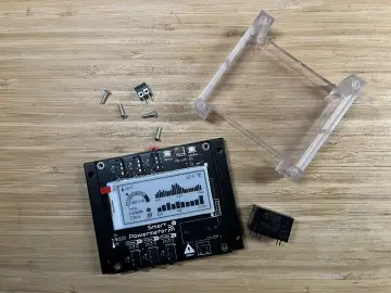
The Board

So,this is the 2D version of my custom-designed PCB. The 220V-to-5V step-down converter is soldered here and the ESP32 board is soldered here. The LED strip and temperature sensors connect through their respective ports, while the AC mains line is soldered here.
3D Model

I used Microsoft 3D Builder to design the 3D model of the unit. This is the base, which will house the custom PCB. This is the cover for the base. This section is where the LED strip will be attached to display the temperature reading. Finally, this 3D model which I downloaded from Thingiverse, will hold the temperature sensor and will be attached to the back of the scale display.

Using my 3D printer, I printed the body of the unit.

I used acrylic colors to color the scale and the numbers on the unit. I wanted to keep my design simple, so, I left the rest white, but feel free to color it to whatever color you like.
Component Assembly

Before soldering the components to the board, let's test them on a breadboard. Connect the temperature sensor and the LED strip to the ESP32 board on the breadboard. Then, use a hot air gun to heat the temperature sensor. As the temperature rises, the LEDs light up sequentially, changing color from blue to green to yellow to red. Perfect, everything is working as expected.

Now, let's solder the ESP32, resistor, and the step-down converter to the board. Next, extract 24 LEDs from the LED strip and attach them to the strip holder.
After that, first slide the temperature sensor's cable, followed by the 3D-printed LED strip holder, into the base of the unit. Then, solder the AC cord, LED strip, and temperature sensor to the board one by one. Once done, close the lid using screws.
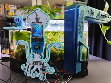
Demo

So, this how my final setup looks like.
In my final setup, I am sending the temperature reading to my home server over Wi-Fi and then using another ESP32 module connected to the miner, I am turning the pedestal fan on or off based on the temperature.
As previously discussed, this can also be accomplished using a relay module connected directly to the custom PCB within the setup.
Thanks
Thanks again for checking my post. I hope it helps you.
If you want to support me subscribe to my YouTube Channel: https://www.youtube.com/@CrazyCoupleDIY
Video: https://youtu.be/WecOhmHxspg
Full Blog Post: https://diy-projects4u.blogspot.com/2026/03/ProgrammableRGBThermometer.html
STL: https://github.com/tarantula3/Programmable-RGB-Thermometer
Github: https://github.com/tarantula3/Programmable-RGB-Thermometer
References
All About PC817 Optocoupler: https://www.youtube.com/watch?v=Rj9H0beMQq8
DIY Relay Module: https://www.youtube.com/watch?v=3n69b4sdDjk
Support My Work
BTC: 1Hrr83W2zu2hmDcmYqZMhgPQ71oLj5b7v5
LTC: LPh69qxUqaHKYuFPJVJsNQjpBHWK7hZ9TZ
DOGE: DEU2Wz3TK95119HMNZv2kpU7PkWbGNs9K3
ETH: 0xD64fb51C74E0206cB6702aB922C765c68B97dCD4
BAT: 0x9D9E77cA360b53cD89cc01dC37A5314C0113FFc3
LBC: bZ8ANEJFsd2MNFfpoxBhtFNPboh7PmD7M2
COS: bnb136ns6lfw4zs5hg4n85vdthaad7hq5m4gtkgf23 Memo: 572187879
BNB: 0xD64fb51C74E0206cB6702aB922C765c68B97dCD4
MATIC: 0xD64fb51C74E0206cB6702aB922C765c68B97dCD4
Thanks, ca again in my next tutorial.
--------------------------------------------------------------------------------------------------------