
Story
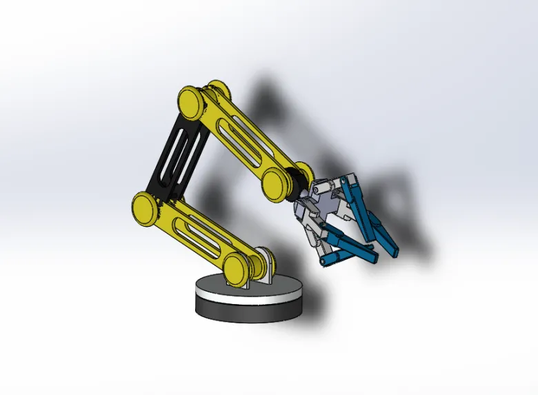
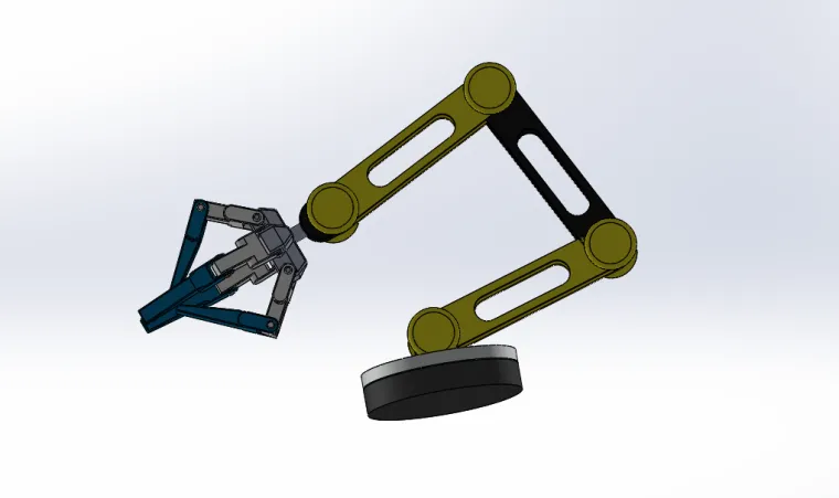
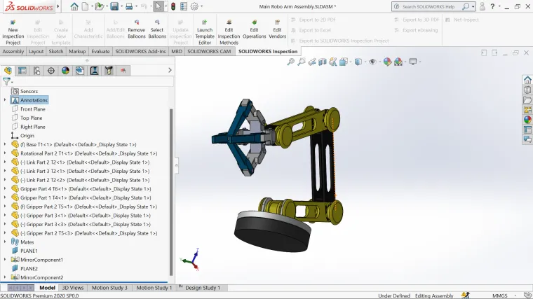
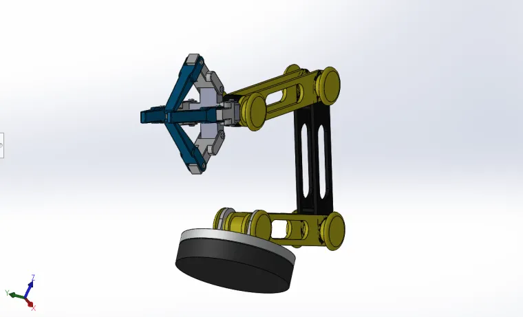
This project presents a 6-Degree-of-Freedom (6-DOF) articulated robotic arm, meticulously designed, modeled, and assembled in SolidWorks. The concept takes inspiration from industrial-grade manipulators such as the UR5 and PUMA 560, which have become global standards in robotic precision, modularity, and workspace optimization.
Built on a serial revolute joint configuration (R–R–R–R–R–R), this robotic arm embodies a perfect balance between mechanical symmetry, motion accuracy, and spatial efficiency. Each axis is carefully engineered to simulate real-world robotic movement — from 360° base rotation to coordinated shoulder, elbow, and wrist articulation — resulting in lifelike trajectories and precise end-effector positioning.
The entire design mirrors the human arm’s structure and dexterity, demonstrating how theoretical kinematics can be translated into mechanical reality through digital engineering. By capturing not only the geometry but also the underlying motion logic, this assembly stands as both a functional digital twin and a visual learning model for industrial and educational use.
Design Overview
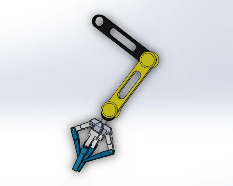
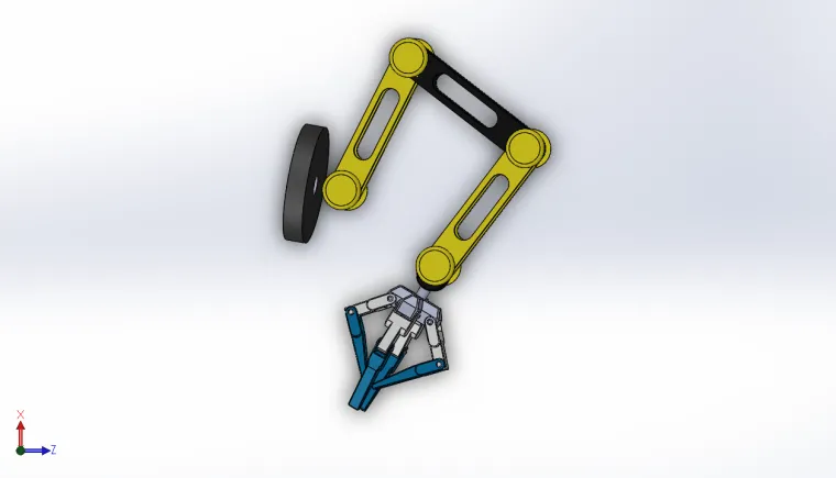
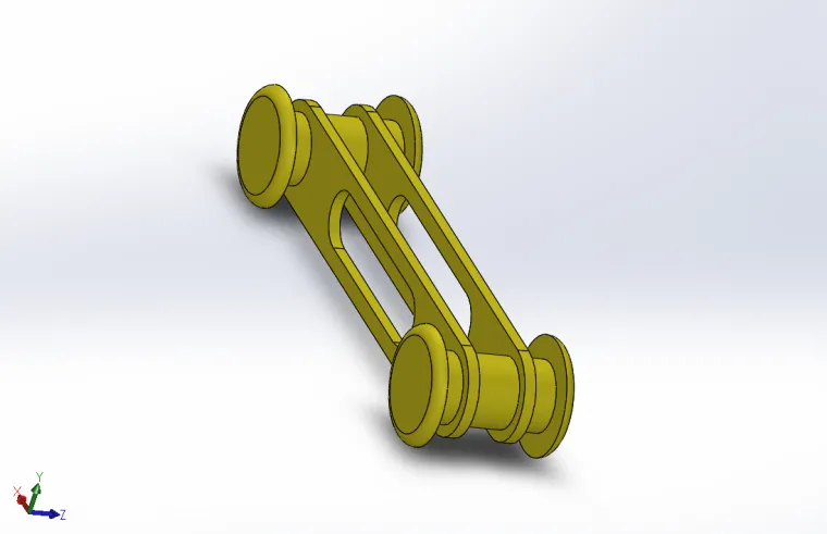
Every mechanical element within the arm — from the base joint to the gripper — is defined with engineering precision. The design consists of five primary links and a dual-link gripper, giving it exceptional reach and dexterity for its size. Each joint is revolute, allowing rotational degrees of freedom that together form a smooth, continuous workspace.
The proportional link lengths ensure torque balance and stability during motion simulation. Each rotational joint was assigned practical mechanical limits to reflect realistic actuator constraints, ensuring that the arm’s motion remains both feasible and collision-free.
With a total reach of approximately 1.53 meters, the arm defines a working dome of nearly 14.7 cubic meters, forming an elegant hemispherical workspace typical of high-precision manipulators. Despite its compact footprint, it achieves significant reach and orientation versatility — demonstrating an optimized ratio of reach-to-size efficiency.
Kinematic Accuracy and DH Configuration
The model’s backbone lies in its Classical Denavit–Hartenberg (DH) configuration, which mathematically represents the relationship between links and joints. Each DH parameter — link length, twist, offset, and joint angle — was derived and aligned within the SolidWorks coordinate system to ensure perfect mapping between physical geometry and analytical modeling.
This allows the robotic arm to be fully compatible with forward and inverse kinematic algorithms, enabling positional calculations, motion planning, and workspace analysis. The kinematic model can be directly imported into simulation environments such as MATLAB Simscape, CoppeliaSim, or ROS-based visualization tools (RViz) for deeper motion studies and path planning.
Each joint contributes a specific degree of freedom:
-
J1: Base rotation providing 360° azimuth sweep.
-
J2: Shoulder pitch for vertical lifting motion.
-
J3: Elbow rotation controlling reach and folding.
-
J4: Wrist pitch refining end-effector alignment.
-
J5 & J6: Dual-axis wrist and gripper rotation, ensuring precise object manipulation and orientation control.
These six revolute axes allow the end-effector to reach any position within its spherical workspace, perform orientation adjustments, and execute complex multi-axis tasks such as pick-and-place operations, arc following, or path tracing.
Motion Study and Simulation
Using SolidWorks’ built-in Motion Study and Assembly Mates, each joint has been assigned a rotational constraint corresponding to its DH axis orientation. This enables seamless motion animation, forward trajectory visualization, and angular sweep simulation.
The motion analysis displays realistic mechanical behavior, including acceleration, damping, and path tracing of the gripper tip. The ability to view the end-effector’s trace curve offers valuable insight into reach optimization and path planning efficiency.
In this digital prototype, the workspace envelope can be visualized as a smooth 3D dome — a critical aspect of robotic performance evaluation. This dome illustrates how the combination of shoulder, elbow, and wrist movements generates an uninterrupted motion range within a defined radius, ensuring maximum spatial coverage and minimal dead zones.
Engineering Focus: Precision and Realism
What sets this project apart is the commitment to mechanical realism and engineering depth. The arm is not merely a visual CAD model; it is structured with mechanically accurate linkages, balanced torque distribution, and realistic angular limitations. Every detail — from revolute joint orientation to link alignment — has been refined to ensure that simulated motion reflects real actuator constraints.
The rotary joint axes are perfectly aligned with practical servo motor configurations, making it easy to map CAD rotations to real motor angles. This realism allows the model to serve as a base for hardware integration, transforming a digital concept into a physical robot through straightforward adaptation.
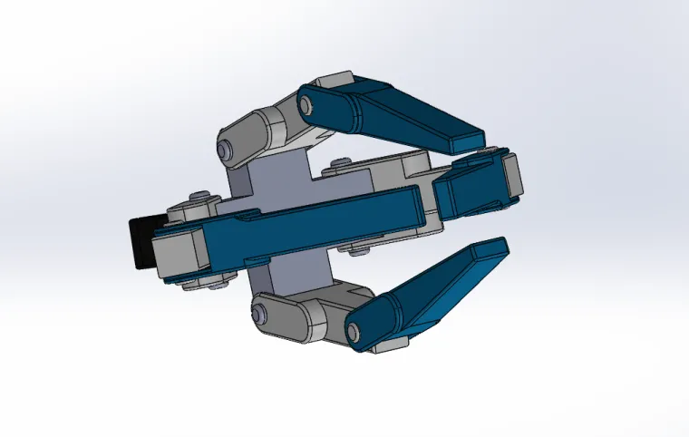
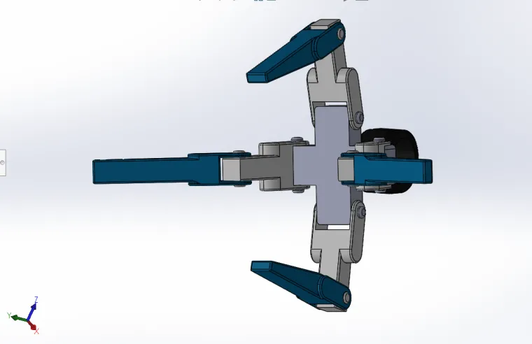
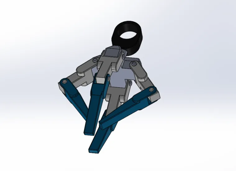
The gripper section, modeled as a dual-link assembly, demonstrates the importance of end-effector design in precision handling. The dual linkage improves parallel grip motion and maintains object stability under different angular postures — a common challenge in robotic manipulation.
Here you Can find Full Kinematic Synthesis
https://grabcad.com/library/robotic-arm-chain-1
Technical Highlights
-
6 fully actuated revolute joints providing complete spatial freedom.
-
1.53 m total reach, covering a broad working envelope.
-
14.7 m³ effective workspace volume, forming a hemispherical dome.
-
360° continuous base rotation, ideal for wide-area manipulation.
-
Mechanically optimized link proportions for stable torque flow.
-
Accurate Denavit–Hartenberg parameters for real-world mapping.
-
Smooth, collision-free joint motion across all rotational axes.
-
Dual-link gripper design for improved end-effector control.
-
Compatible with simulation platforms such as ROS, MATLAB, and CoppeliaSim.
Integration and Compatibility
One of the project’s most practical strengths is its hardware readiness.
The CAD structure is designed for easy integration with:
-
Microcontroller-based systems (Arduino Mega, ESP32, STM32) for educational or prototype-level control.
-
PLC systems (Siemens S7-1200, Mitsubishi FX5U, Delta DVP) for industrial-grade motion control.
The defined joint axes correspond directly to servo or stepper control signals, enabling real-time actuation through PWM or pulse-train commands. This makes the model suitable not only for virtual demonstrations but also for real mechatronic implementations where CAD-to-control mapping is essential.
Using microcontrollers, the arm can be controlled through forward/inverse kinematic algorithms written in Python, C++, or MATLAB. For higher reliability, PLC integration allows synchronized multi-axis control using industrial communication standards like Modbus, EtherCAT, or Profinet.
Applications and Use Cases
This robotic arm assembly extends far beyond visual modeling. It provides a practical reference for a wide range of applications, including:
-
Kinematic Visualization: Perfect for understanding how DH parameters translate into motion.
-
Trajectory Simulation: Enables smooth multi-axis motion testing within CAD.
-
Control Algorithm Development: Useful for validating FK/IK and PID tuning.
-
Workspace Analysis: Helps in evaluating reach efficiency and motion constraints.
-
Education and Research: A high-quality example of industrial-grade robotic design principles.
-
Hardware Prototyping: Can be adapted directly for microcontroller or PLC-based control setups.
The Engineering Philosophy Behind the Design
This project was not just about building a model — it was about translating engineering theory into visual intelligence. Each joint, constraint, and geometric relationship was intentionally crafted to teach the fundamentals of robotics: degrees of freedom, forward/inverse kinematics, workspace generation, and motion coordination.
The design reflects how precision geometry and control theory converge in modern automation. It demonstrates how a set of six rotary joints, each seemingly simple on its own, can combine to create fluid, human-like motion capable of complex path-following and task execution.
Every motion within the model follows physically plausible mechanics. The joint axes are orthogonally aligned, minimizing singularities and mechanical interference, while the link lengths are optimized for reach and load balance. This precision ensures that even in a purely virtual environment, the arm moves with smooth continuity — a signature of good kinematic architecture.
A Digital Twin for the Real World
Beyond static visualization, this robotic arm functions as a digital twin — a virtual representation that mirrors a real machine’s movement and structure. The model can serve as a testing platform for trajectory control, path planning, and collision detection before any physical prototype is built.
By applying forward kinematics, the model can compute the end-effector’s 3D position based on input joint angles, while inverse kinematics algorithms can determine the required joint angles to reach a target position. This data-driven simulation approach forms the backbone of modern robotics design workflows, where digital testing significantly reduces development time and cost.
Conclusion
This 6-DOF robotic arm stands as a fusion of engineering design, mechanical logic, and digital precision. It demonstrates how intelligent CAD modeling can replicate real robotic behavior, bridging the gap between conceptual design and mechatronic functionality.
With a structure inspired by industrial icons like the UR5 and PUMA 560, the model highlights the synergy between form, function, and motion — delivering a realistic representation of a modern robotic manipulator.
From its precisely defined revolute joints to its balanced mechanical proportions, every detail of this assembly reflects a genuine understanding of robotics principles. It captures how geometry, mathematics, and control systems come together to produce synchronized motion and spatial awareness.
This project is more than a 3D assembly — it’s a study in mechanical intelligence. It’s a demonstration of how kinematic accuracy, structural design, and digital simulation can converge to form a near-realistic robotic system — ready for simulation, research, and industrial prototyping.
Created to inspire mechanical intelligence — built to move like reality.