Story
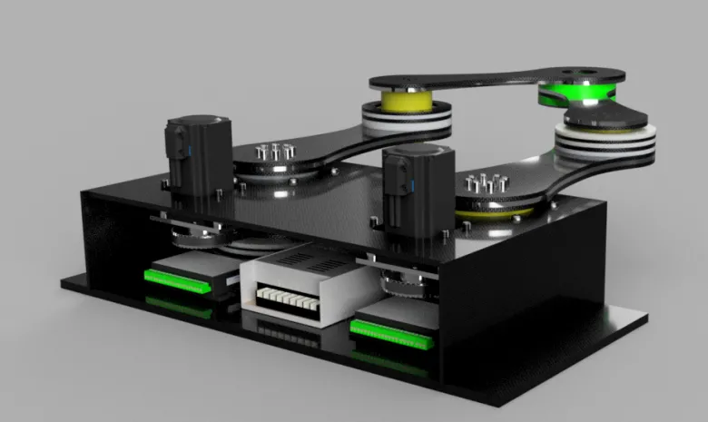
A low-cost, education-friendly SCARA robot with 3 planar DOF (base rotation + shoulder + elbow) and a position-controlled pneumatic gripper for Z/height pick-and-place. It’s designed around semi-mainstream components and hybrid fabrication: 2D CNC plates + FDM-printed brackets (nylon/PA or CF-nylon), assembled into robust 3D mechanisms.
How it works
-
Arm kinematics: Two coaxial revolute joints place the forearm; a third joint (wrist/forearm) aligns the gripper.
-
Parallel actuation layout: Motors are placed near the base with timing belts to keep moving mass low.
-
Z & grip: A compact pneumatic vertical slide or lift plus a position-controlled pneumatic gripper handles varying part heights.
-
Control loop: Encoders → controller (e.g., STM32/ESP32) → motor drivers → actuators; high-level commands come from a PC (Python) doing inverse kinematics.
Build it: step-by-step
0) Bill of Materials (typical)
-
Motion: 3× NEMA-17/23 steppers (or compact BLDC servos), GT2/HTD pulleys & belts, sealed radial bearings (608/6001), shoulder/elbow shafts, idlers.
-
Structure: 6–8 mm aluminum (or G10/FR4) plates for base/links, 3–4 mm for brackets; FDM-printed spacers, guards, wire guides (nylon/PA-CF).
-
Pneumatics: Mini cylinder or slide for Z, position-controlled gripper (with proportional valve or step-valve + pressure sensor), regulator, tubing, fittings.
-
Electronics: MCU (STM32/ESP32), stepper drivers (TMC5160/2209 or servo drivers), 24 V PSU, 5 V rail, limit/home switches, incremental encoders, e-stop.
-
Misc: Cable chain, ferrules, heat-set inserts, Loctite 243, thread-forming screws for plastics.
1) CAD & drawings
-
Lay out 2D plates (base, shoulder, elbow, motor/bearing plates) so they can be CNC-cut from sheet.
-
Add datum features (dowel holes/slots) to make alignment foolproof.
-
Export: DXF for plates, STL for printed parts.
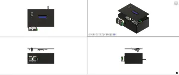
Image to include: Exploded view labeling plates, printed brackets, and pulley paths.
2) Fabrication
-
CNC plates: 2D mill; deburr edges; ream bearing bores to size.
-
3D prints: Nylon/PA-CF, 0.2–0.28 mm layer, 4+ perimeters, 40–60% infill; orient to maximize fiber along load paths.
Image to include: Flat-lay of all cut plates + printed parts with part numbers.
3) Mechanical assembly
-
Press bearings into link plates; verify slip-fit shafts.
-
Build base: mount motors, idlers, and first-stage pulleys; route belts but leave slack.
-
Stack shoulder then elbow assemblies; install shafts and spacers; check free motion.
-
Tension belts (finger-tight + ¼ turn) and apply a drop of threadlocker.
-
Mount pneumatic Z slide and gripper; verify full travel.
Image: Belt routing close-ups; Short video (10–20 s): arm moving freely by hand.
4) Electronics & pneumatics
-
Wire MCU → drivers → motors; add home switches (base, shoulder, elbow) and an E-STOP in series with driver enable.
-
Plumb regulator → valves → cylinder/gripper; place a pressure sensor for closed-loop grip force.
-
Add strain relief + cable chain; keep air lines out of the work envelope.
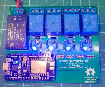
Image: Wiring diagram; Video: power-on + E-STOP test.
5) Firmware bring-up
-
Set steps-per-rad (or encoder ticks/rad), max accel/velocity, and soft limits.
-
Home sequence: base → shoulder → elbow → Z; store offsets.
-
Expose a simple UART/USB API:
GOTO x y z θ,OPEN,CLOSE,SET_GRIP_FORCE.
Clip: Serial console showing commands and motion.
6) Kinematics & PC control
-
Implement inverse kinematics (IK) for SCARA: given (x, y) solve shoulder/elbow; wrist aligns tool angle.
-
Add workspace checks and singularity guards (elbow-up/down).
-
Python control script: teach points, linear move (interpolate in task-space), and pick-place sequence.
Video: Picks from tray A, places to tray B.
7) Calibration & testing
-
Link length calibration: move to gauge points, fit actual lengths to minimize IK error.
-
Backlash/belt tension: jog direction reversals; tune jerk/accel; retension belts if overshoot.
-
Pneumatic tuning: set regulator, valve PWM/step mapping, and grip force vs. pressure curve.
Image: Calibration fixture or printed jig; Clip: accuracy test placing pins into a pegboard.
8) Safety & enclosure (recommended)
-
Interlocked acrylic guard or light curtain; e-stop within reach; current limits set conservatively.
-
Label pinch points and add soft end-stops in firmware.