

Story
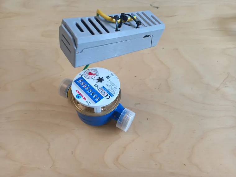
The main goal of this project is show how set-up the Ai-On-The-Edge-Cam board to digitalize your old watermeter/energy meter and to send digital data via LoraWan to The Things Network. From there you can get your data to any service that supports MQTT(for example HomeAssistant). You can also use Wifi or Ethernet instead of LoraWan.
Step 1 - Create End Device:
1)Register at https://www.thethingsnetwork.org/get-started
2)Then go to https://console.cloud.thethings.network
3)Choose the cluster you want to use. In this tutorial, I’ll go with EUROPE 1.

4)Create a new application. You can pick any ID you like. After that, click Register end device and select Manual.

5)Select the frequency based on your region (I’m using Europe).
The JoinEUI is just zeros — this is the default value set by manufacturers.
Choose Frequency plan: Europe 863-870 MHz (SF9 for RX2 - recommended)
Choose LoRaWAN version: LoRaWAN Specification 1.0.3

6)Generate the parameters and register the new end device.

7)In the sidebar, configure the payload formatter to convert bytes into characters for later use.
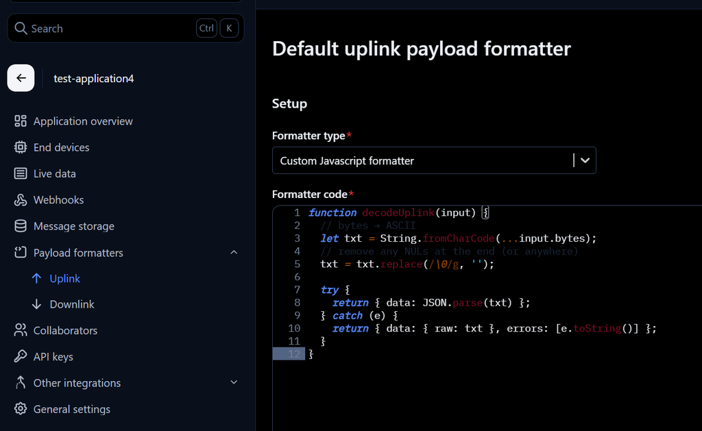
Go to Payload Formatters > Uplink, select Custom JavaScript Formatter, and paste the following script:
function decodeUplink(input) {
// bytes → ASCII
let txt = String.fromCharCode(...input.bytes);
// remove any NULs at the end (or anywhere)
txt = txt.replace(/\0/g, '');
try {
return { data: JSON.parse(txt) };
} catch (e) {
return { data: { raw: txt }, errors: [e.toString()] };
}
}
In the third step, you’ll need these parameters: AppEUI, DevEUI, and AppKey.
Step 2 - Setup Lora-Shuttle LORAWAN Module:
Code repository for LORAWAN module:
https://github.com/allexoK/Lora-Shuttle-examples/tree/main
You’ll also need to install the Heltec framework.
1)In Arduino IDE search in Library manager for "heltec esp32" and install it.

2)Copy the example code I2CShuttleSlave from github.
3)Select right board, go to Tools > Board > ESP32 > Heltec Wireless Mini Shell.

4)Don't forget change region depends where you live ,it was tested for EU868 and US915.

5)Copy the example code I2CShuttleSlave from github.
6)Connect the ESP32-C3 board via USB.
7)Under Tools > Port, select the correct port.
8)Click Upload and wait until you see “Done uploading”.
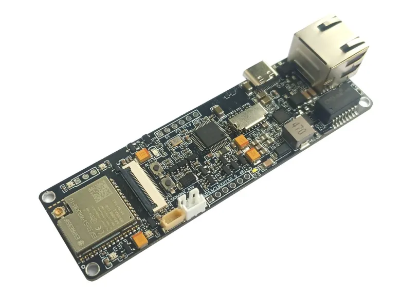
Step 3 - Flashing ESP32-S3 AI ON THE EDGE:
First, you need to flash the ESP32-S3 board (if it didn’t come pre-flashed).
Flashing tool: https://allexok.github.io/AI-on-the-edge-device/

1)Connect the board via USB.
2)Click Connect.
3)Select the correct port.
4)Confirm the installation.
In the notes, you’ll see that the SD card must be configured either manually or via OTA.
In this tutorial, I’ll show you how to do it manually:
Link for setup SD card with pictures: https://jomjol.github.io/AI-on-the-edge-device-docs/Installation/#3-sd-card
You can download the required files here: https://github.com/allexoK/AI-on-the-edge-device/releases
Name of file i will use: AI-on-the-edge-device__manual-setup-s3__Vxx.x.x.zip
5) Disconnect ESP32-S3 board from USB and take SD card
6)Open manual-setup-s3 zip folder, open SD-CARD.zip. Extract its contents to an SD card using like SD card reader, then insert the SD card into the ESP32-S3 board.
Default is ethernet version.
7) Open your IDE (e.g., Arduino IDE, PlatformIO) and start the Serial Monitor. Then connect the Ethernet cable and USB-C to the ESP32-S3 board. You should see the following output in the Serial Monitor:
I (12543) LAN: Assigned IP: xxx.xx.xx.xxx
I (12543) esp_netif_handlers: eth ip: xxx.x.xx.xxx, mask: 255.255.255.0, gw: xxx.xx.xx.x
8)Copy this IP address, open it in your web browser, and go through the setup process.
More about Initial Setup and setup camera and reference image:
https://jomjol.github.io/AI-on-the-edge-device-docs/initial-setup
9)When finished, click the Reboot button or reconnect USB cable.

If you don’t have wlan.ini or lan.ini file, the board will create one automatically. In the serial monitor, you’ll see output similar to:
I (5226) WIFI AP: started with SSID "AI-on-the-Edge", password: "", channel: 11. Connect to AP and open http://xxx.xxx.x.x
I (5226) esp_netif_lwip: DHCP server started on interface WIFI_AP_DEF with IP: xxx.xxx.x.x
Just copy IP and paste into browser, from here, you can choose whether to use Wi-Fi or Ethernet. Then return to the 7. step
If there's error with wlan.ini or lan.ini like:
E (5206) LANINI: Unable to open file (read). Device init aborted!
W (5216) MAIN: lan.ini not found, proceeding to wlan.ini
I (5226) WLANINI: SSID:
I (5226) WLANINI: Password: XXXXXXXX
I (5236) WLANINI: RSSIThreshold: 0
E (5246) WLANINI: SSID empty. Device init aborted!
I (5246) main_task: Returned from app_main()
remove wlan.ini or lan.ini from SD card and Open your Wi-Fi settings and connect to the access point.
From here, you can choose whether to use Wi-Fi or Ethernet. Then return to the 7. step
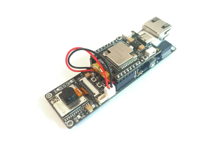
Step 4 - Config LORAWAN in Web Interface
1) Connect LORAWAN module to ESP32-S3 board
2)Go to Settings > Configuration and wait a few seconds for the page to load.

3)Search for LORAWAN and copy the required details into the corresponding boxes and reboot.

4)Go to The Things Network website and navigate to: Application > End Devices > Live Data

Some logs from serial monitor:
(53485) POSTPROC: main: Raw: 2NN.0211, Value: , Status: Rate too high - Read: 277.0211 - Pre: 177.2163 - Rate: 99.8048
I (53575) LORAWAN CLASS FLOW: Publishing data via Lorawan...
I (53585) LORAWAN PUBLISH: {"name":"battery_voltage_value_mV","msg":"3956"}
I (61895) LORAWAN PUBLISH: {"name":"mainerror","msg":"Rate too high - Read: 277.0211 - Pre: 177.2163 - Rate: 99.8048"}
I (71405) LORAWAN PUBLISH: {"name":"mainchangeabsolut","msg":"0.0000"}
That's all for this tutorial thank you for reading.