








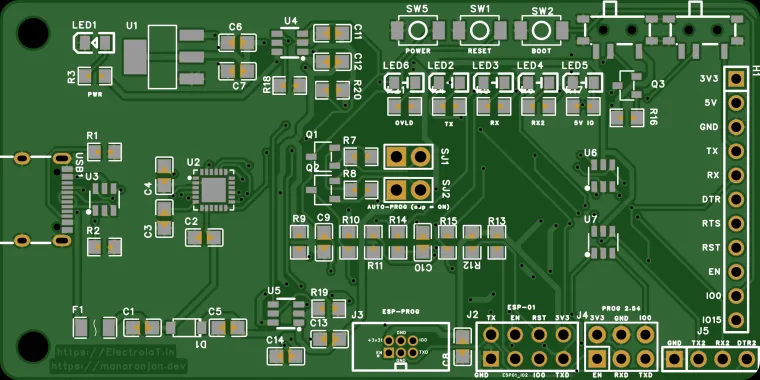
Story
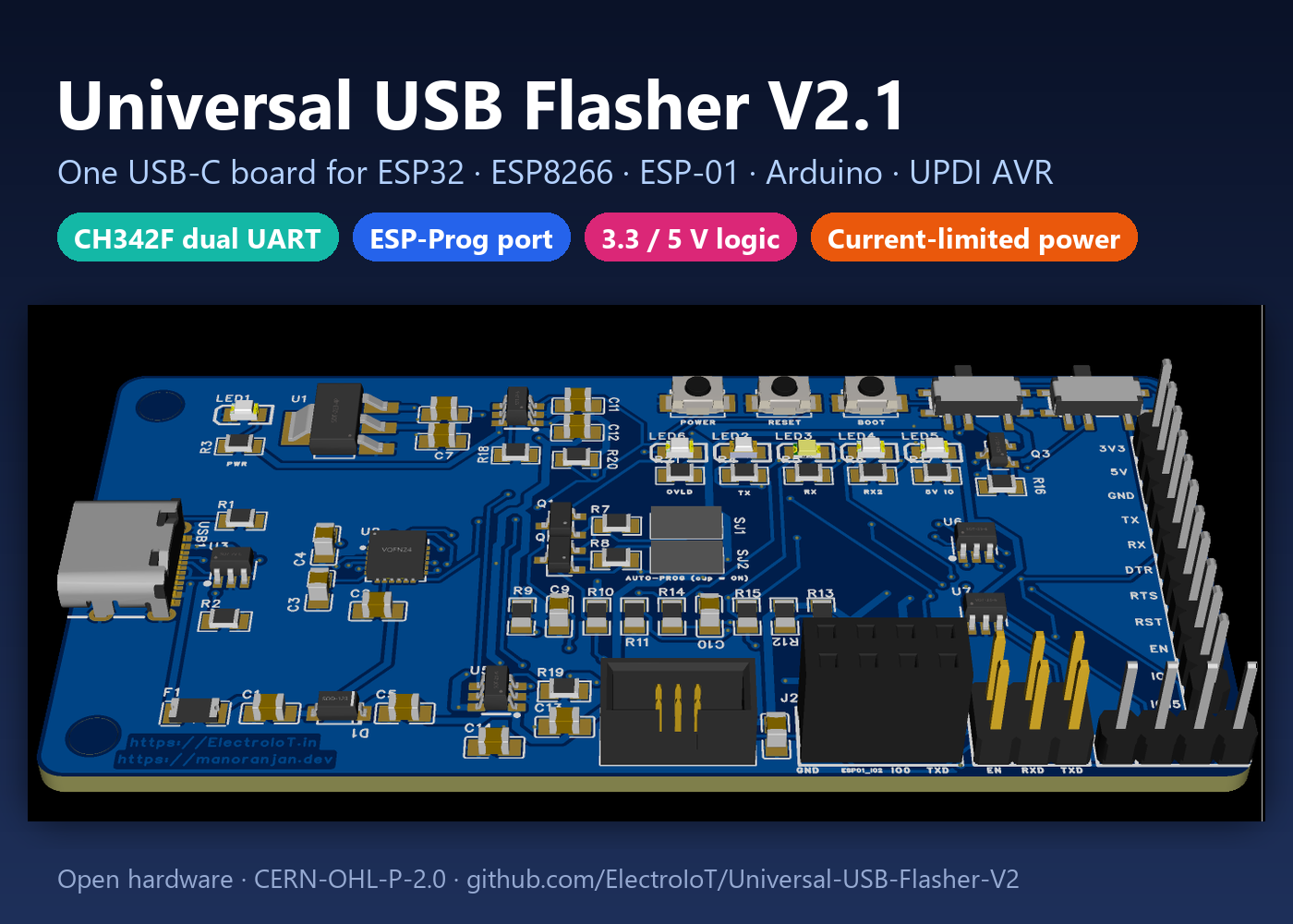
⚡ One USB-C board to flash almost everything makers use
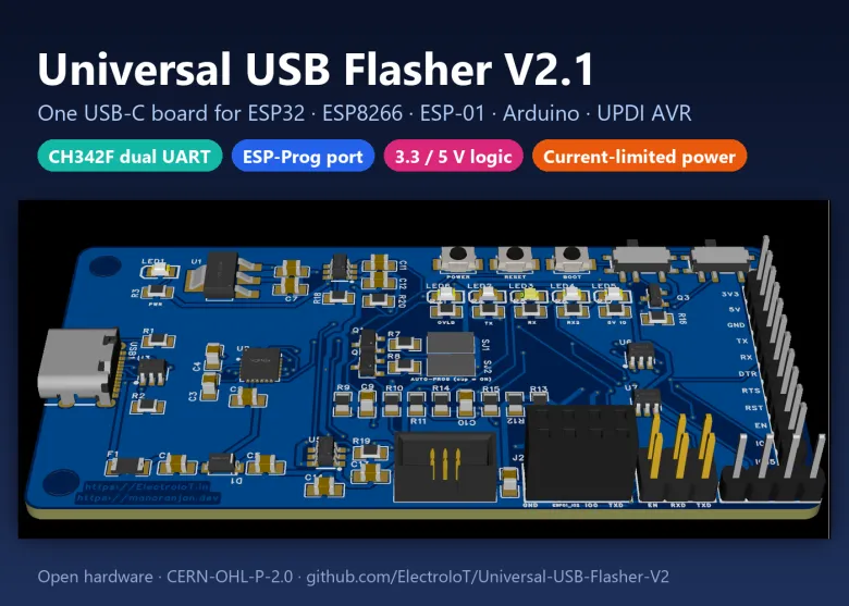
Universal USB Flasher V2.1 is an open-source USB-C programmer and serial adapter. One board flashes ESP32 (all variants), ESP8266 / ESP-12F, plug-in ESP-01 modules, Arduino / ATmega boards and the new UPDI AVR chips (ATtiny 0/1/2-series, AVR-DA/DB/DD). A second UART lets you watch another device's serial log at the same time.
📌 Status: the design is finished (8-page schematic, routed 2-layer PCB, DRC 0 errors). It has not been built or tested yet. Build photos and test results will be added here.
🤔 Why I made it
Flashing different chips usually means a drawer full of adapters: a USB-UART for ESP boards, an ESP-Prog, a 5 V adapter for Arduino and a SerialUPDI cable for new AVRs, plus jumper wires for every chip. My first board (Universal USB To Serial Flasher V1, CH340C) put some of that on one board, but it had one UART, 3.3 V logic only, no fuse, no proper Arduino reset pin and an unreliable auto-boot transistor. V2 fixes all of that on one 80 × 40 mm board.
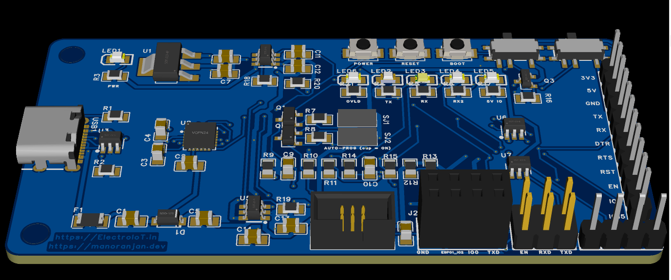
✨ Features
- 🔀 WCH CH342F dual UART: two COM ports from one USB-C cable, up to 3 Mbaud, native driver on Windows 10/11, macOS and Linux.
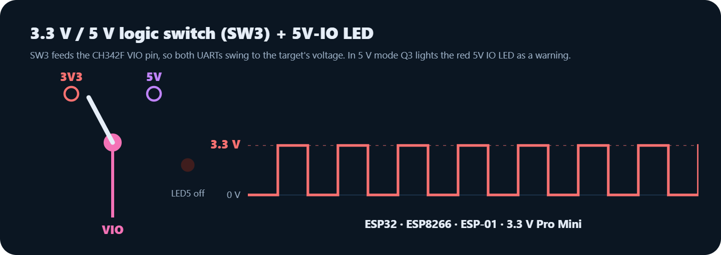
- 🔌 3.3 V / 5 V logic switch (SW3). The CH342F VIO pin follows the switch, and a red 5V IO LED warns you when the lines swing at 5 V.
- 🔁 ESP auto-program: the classic two-transistor EN / IO0 circuit, so esptool, Arduino IDE and PlatformIO flash with no button pressing. Pull the SJ1 / SJ2 jumper caps for a plain USB-UART.
- 🧩 ESP-Prog compatible port: J3 is Espressif's 2×3 1.27 mm PROG box header; J4 has the same pinout at 2.54 mm for cables or a pogo-pin jig.
- 📡 ESP-01 socket (J2): plug in an ESP-01 / 01S and flash it with no wires. GPIO2, RST and CH_PD pull-ups are on the board.
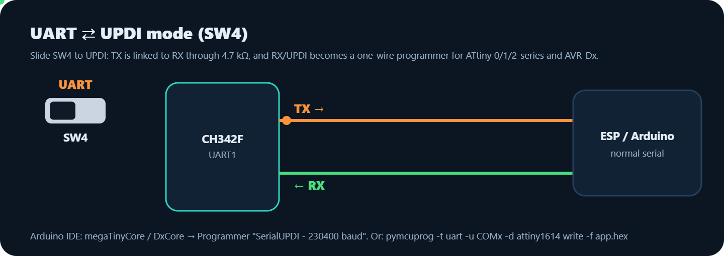
- 🔧 UPDI mode (SW4): TX → 4.7 kΩ → RX turns the RX pin into a SerialUPDI programmer for modern AVR chips.
- ♾️ Arduino auto-reset: RST = DTR through 100 nF with a 10 kΩ pull-up.
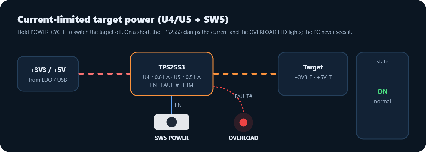
- 🛡️ Current-limited target power: two TI TPS2553 switches limit 3.3 V to about 0.6 A and 5 V to about 0.5 A. Hold the POWER button to cut target power; the OVERLOAD LED shows a trip.
- ⚡ ESD on every line: USBLC6-2SC6 on USB D+/D−, two USBLC6-4SC6 arrays on TX, RX, DTR, RTS, EN, IO0, TX2 and RX2, plus a 500 mA PTC fuse and a Schottky back-feed diode.
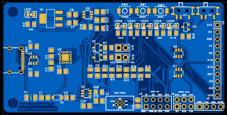
- 💡 6 status LEDs: PWR, TX, RX, RX2, 5V IO and OVERLOAD.
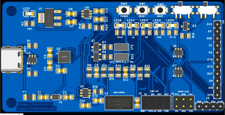
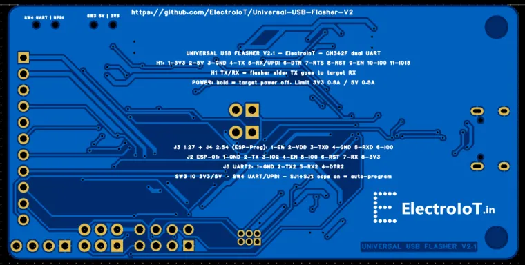
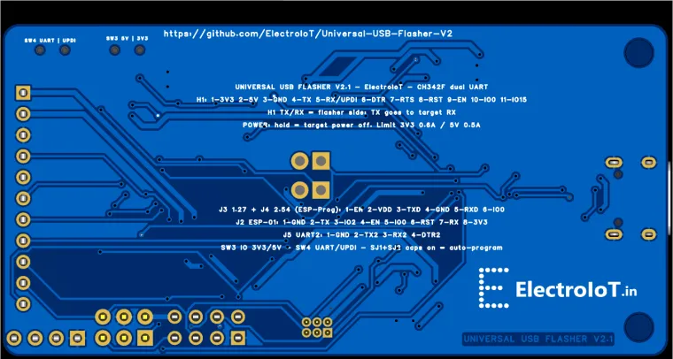
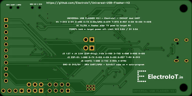
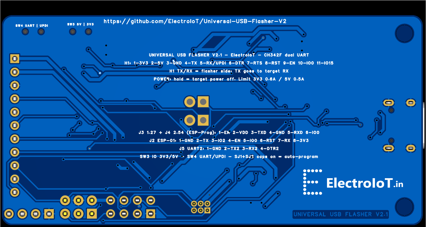
- 🏷️ Every pin labelled on the top silkscreen, and the full pinout printed on the bottom.
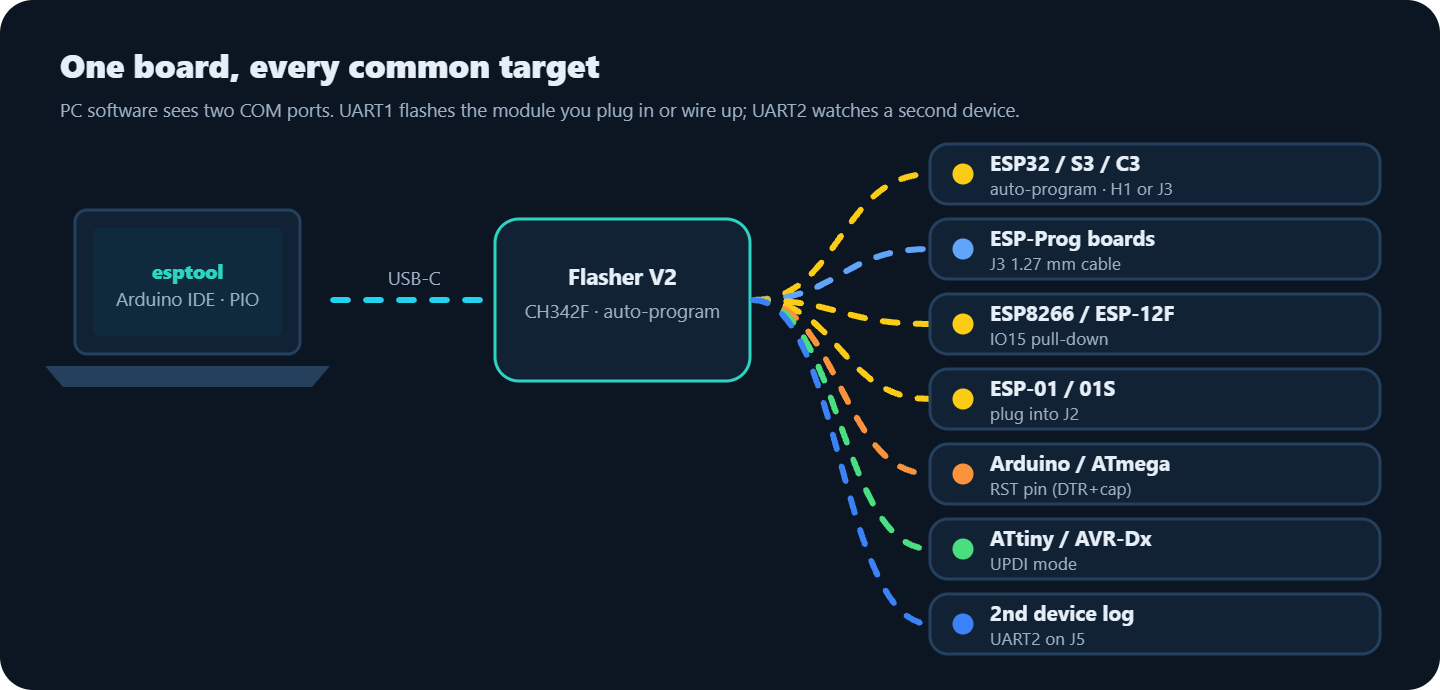
⚙️ How it works
Dual UART
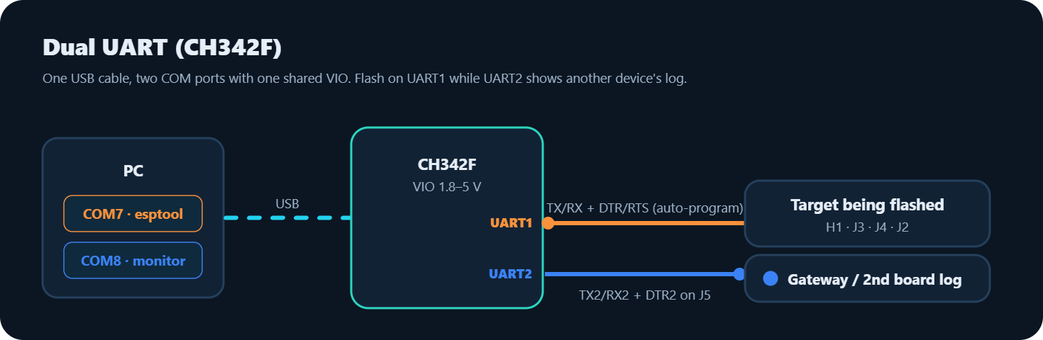
UART1 of the CH342F goes to every programming port (H1, J3, J4 and the ESP-01 socket). UART2 goes to J5, so you can flash one board and read the log of another at the same time.
Auto-program (EN / IO0)
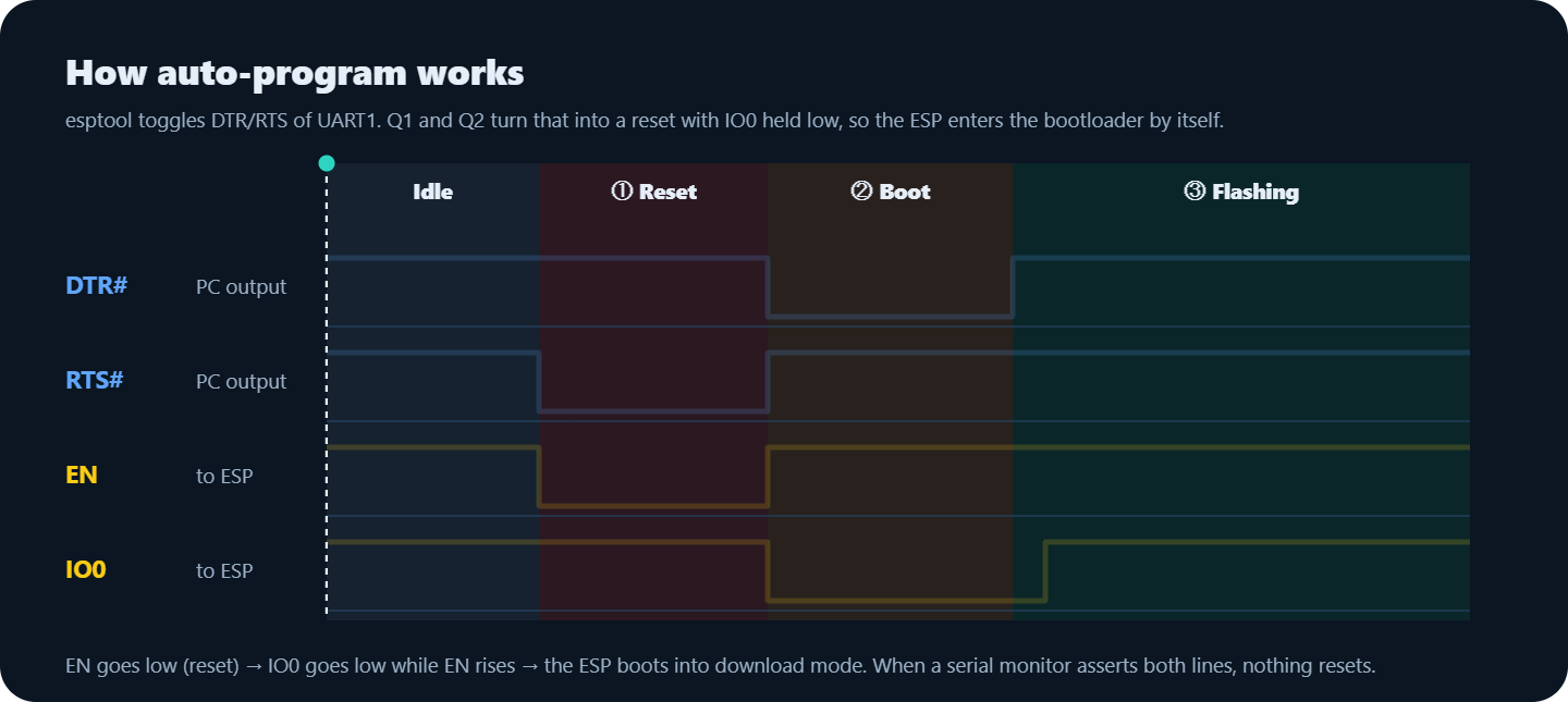
Two MMBT3904 transistors are cross-wired to DTR and RTS. When esptool toggles DTR/RTS, they pull EN low (reset) and IO0 low (boot mode) in the right order. When both lines are in the same state, nothing happens, so opening a serial monitor does not reset the board.
Logic level (VIO)
SW3 feeds the CH342F VIO pin from 3.3 V or from the 5 V rail, so TX/RX/DTR/RTS swing at the target's own voltage. A PNP transistor lights the red 5V IO LED whenever VIO is above 3.3 V.
Protected target power
USB VBUS passes a PTC fuse and a Schottky diode, then an SGM2212 LDO makes 3.3 V. Both target rails (3V3_T and 5V_T) go through TPS2553 power switches with an ILIM resistor each, so a short on your target trips the switch in microseconds instead of crashing the USB port.
UPDI
Slide SW4 to UPDI and the board becomes a SerialUPDI programmer: TX joins RX through 4.7 kΩ, and the RX pin of H1 is the UPDI line.
📍 Pinout
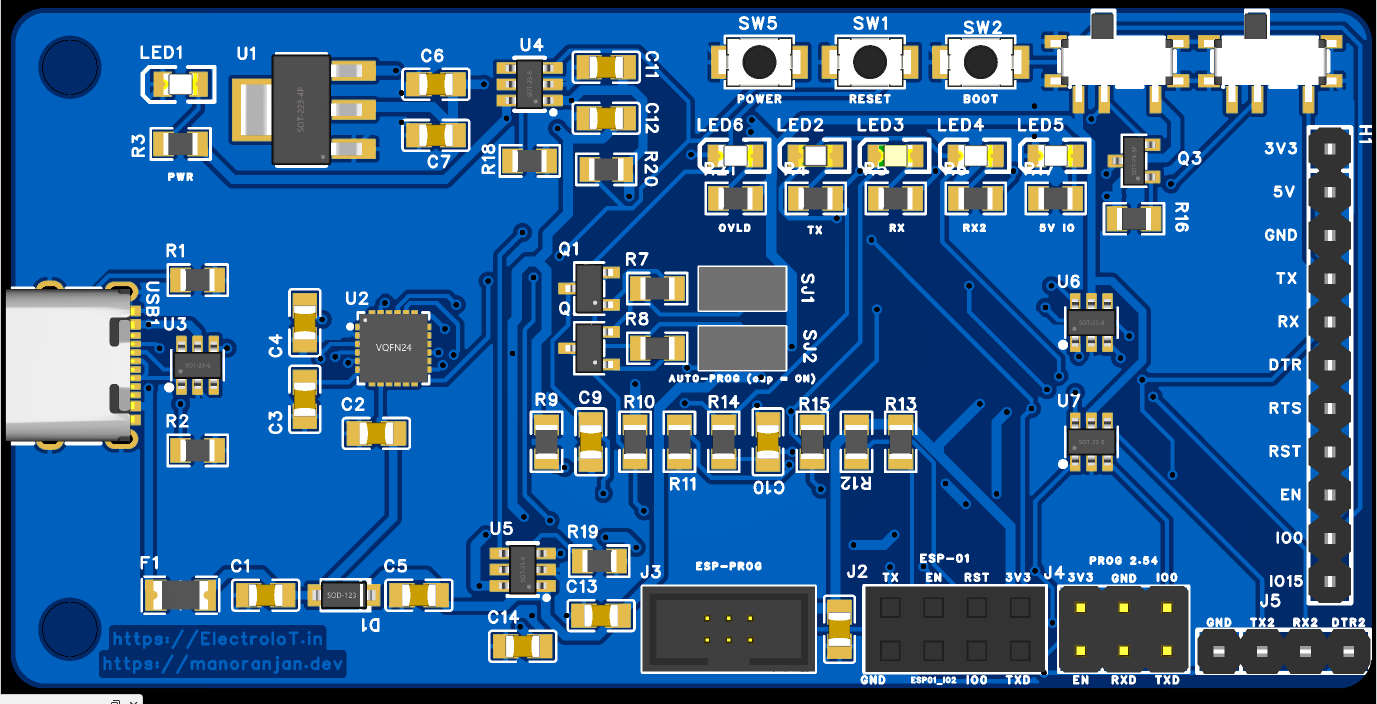
- H1 (1×11, 2.54 mm): 1 3V3 · 2 5V · 3 GND · 4 TX · 5 RX/UPDI · 6 DTR · 7 RTS · 8 RST · 9 EN · 10 IO0 · 11 IO15. TX/RX are named from the flasher side: TX goes to the target's RX.
- J3 (1.27 mm box) / J4 (2.54 mm), ESP-Prog order: 1 EN · 2 VDD · 3 TXD · 4 GND · 5 RXD · 6 IO0
- J2 ESP-01 socket: 1 GND · 2 TX · 3 IO2 · 4 EN · 5 IO0 · 6 RST · 7 RX · 8 3V3
- J5 UART2: 1 GND · 2 TX2 · 3 RX2 · 4 DTR2
- Controls: SW5 POWER (hold = target off) · SW1 RESET · SW2 BOOT · SW3 5V | 3V3 · SW4 UART | UPDI · SJ1 + SJ2 caps on = auto-program
🧪 Using it
- ESP32 / ESP8266: connect H1 (or an ESP-Prog cable on J3), fit SJ1 + SJ2, then run
esptool.py --port COMx write_flash 0x0 firmware.binor press Upload in Arduino IDE / PlatformIO. - ESP-01: plug the module into J2 and flash it the same way.
- Arduino / ATmega328P: SW3 to 5V, connect TX, RX, GND and RST (auto-reset), then upload as normal.
- ATtiny 0/1/2 and AVR-DA/DB/DD: SW4 to UPDI, connect RX/UPDI and GND, choose SerialUPDI in megaTinyCore / DxCore.
- Second device log: connect it to J5 and open the second COM port.
🛠️ Board
- 80 × 40 mm, 2 layers, 1.6 mm FR-4, 1 oz copper, two M3 holes
- Power tracks 0.5–0.6 mm, signals 0.254 mm, vias 0.3 / 0.6 mm, GND pour on both sides, DRC 0 errors
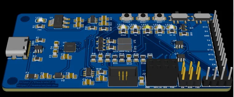
- 66 parts, every one with a manufacturer part number in the BOM. Only U2 (CH342F, QFN-24, 0.5 mm pitch) needs hot air or SMT assembly; the rest is 0805, SOT-23, SOT-23-6, SOD-123, SOT-223 and through-hole headers
- Gerber, BOM, centroid and a 3D STEP model are attached
📂 Open source files
Everything is open under CERN-OHL-P-2.0: schematic pages, netlist, BOM, placement, pinout, Gerber, centroid, 3D STEP, a step-by-step build guide and a bring-up test plan.
👉 GitHub: github.com/ElectroIoT/Universal-USB-Flasher-V2
🚀 What's next
- Order the boards, assemble them and run the bring-up test plan (rails, two COM ports, loopback, current limit, flashing ESP32 / ESP-12F / ESP-01 / Pro Mini / ATtiny1614)
- Pogo-pin jig on J4 for flashing boards with bare PROG pads
- 3D-printed case
Feedback and suggestions are very welcome in the comments! 🙌