Story
Project Description
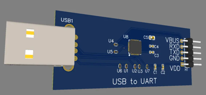
The project is a USB to UART converter
This is a complete PCB project that enables serial communication between a computer (USB) and electronic systems and microcontrollers via the UART interface.
The board is intended for development, testing, programming, debugging, and educational and DIY projects, and is a reliable and common solution for connecting a computer to external components.
The project includes a professional design of a printed circuit board, with all the files required for manufacturing, assembly, documentation, and future editing in industrial software.
The package includes everything needed for manufacturing and assembly
• Electrical schematic (PDF, PNG, SVG, JSON) – shows the connections of the USB components, the communication chip, resistors, connectors, and auxiliary components.
• PCB Layout – full physical design of the printed circuit board, including the layout of components and tracks.
• Gerber Files + Pick & Place – standard files for professional manufacturing and automatic assembly.
• BOM (Bill of Materials) – a complete list of components for assembling the board.
• CAD and 3D files (OBJ / DXF) – for documentation, visualization and mechanical design.
• Altium Designer compatibility files (PCBdoc, Schdoc) – for further development and professional editing.
Folder and file list
1. Schematic – electrical schematic
• Schematic_USB-to-UART_2025-09-18.pdf / .png / .svg – circuit diagram in various formats (document, image, vector).
• SCH_USB-to-UART_2025-09-18.json – an open source file of the schematic for editing.
• This folder centralizes the electrical schematic and clarifies the connections of all system components.
2. Layout (PCB) – Circuit layout
• PCB_USB-to-UART_2025-09-18.pdf / .png / .svg – Display of the PCB board in various formats.
• PCB_USB-to-UART_2025-09-18.json – Source file of the board layout.
• Here is the physical design of the card: component placement, conductor paths and board structure.
3. Gerber files – Manufacturing files
• Gerber_USB-to-UART_PCB_USB-to-UART_2025-09-18.zip – Gerber file archive for PCB manufacturing in the factory.
• BOM_USB-to-UART_2025-09-18.csv – Complete list of components (Bill of Materials).
• PickAndPlace_PCB_USB-to-UART_2025-09-18.csv – Component placement file for automated assembly.
• This folder is intended for manufacturing and assembly according to industry standards.
4. CAD files – 3D and CAD files
• OBJ_PCB_USB-to-UART_2025-09-18.zip – 3D model of the board (OBJ).
• PCB_USB-to-UART_2025-09-18.dxf – DXF file for advanced engineering use.
• Useful for visualization, mechanical design and integration into packages.
5. EasyEDA to Altium – Files for Altium Designer
• Sheet_1_2025-09-18.schdoc – Schematic file optimized for Altium.
• PCB_USB-to-UART_2025-09-18.pcbdoc – PCB layout file optimized for Altium.
• Intended for users interested in continuing professional development in the Altium Designer environment.
Summary
Inside the ZIP file you will find:
• Full electrical schematics
• PCB layout
• Gerber files for manufacturing, including BOM and Pick & Place
• CAD and 3D files
• Files for professional editing in Altium Designer
That is: a complete PCB project from end to end – suitable for documentation, manufacturing, assembly and editing in open and industrial formats.