








Story
Motor control is one of the first challenges you encounter when moving from simple Arduino experiments to robotics and automation projects. An Arduino UNO can generate the control signals required by a motor, but its I/O pins are not designed to supply the current needed to drive motors directly. A motor driver provides the required interface between the microcontroller and the motor.
The L293D Motor Driver Shield is a convenient option for Arduino-based projects because it combines motor driver circuitry with connectors that make it easier to work with DC motors, stepper motors, and servo motors. In this project, we will look at the architecture of the shield and use it with an Arduino UNO to control an SG90 micro servo. The same shield can also be used for DC and stepper motor applications, which makes it useful when developing different types of motion-control prototypes.
What Is the L293D Motor Driver Shield?
The L293D Motor Driver Shield is an Arduino-compatible expansion board designed to interface motors with an Arduino UNO. It uses L293D driver ICs to handle the switching required to operate motors while the Arduino provides the control signals.
An L293D contains two H-bridge circuits. An H-bridge allows the direction of current through a motor to be changed, which makes bidirectional DC motor control possible. The shield uses two L293D ICs, providing four motor output channels.
Depending on how the outputs are used, the shield can control up to four DC motors or two stepper motors. It also includes two dedicated servo connections, making it possible to combine different motor types in the same Arduino-based system.
The shield is therefore useful for projects such as small robotic vehicles, pan-and-tilt mechanisms, automated mechanisms, experimental motion systems, and educational robotics platforms.
L293D Motor Driver Shield Features
Some of the important features of this shield include:
-
Four bidirectional DC motor outputs
-
Support for two stepper motors
-
Two dedicated servo motor connectors
-
Motor supply range of approximately 4.5V to 24V
-
L293D driver channels rated for up to 600mA continuous current
-
74HC595 shift register for extending motor control outputs
-
External motor power input
-
5V-compatible logic
-
Convenient Arduino-compatible form factor
The actual motor power requirements should always be checked before connecting a motor. The current rating of the driver should not be treated as a recommendation to operate a motor continuously at its maximum value.
Hardware Overview
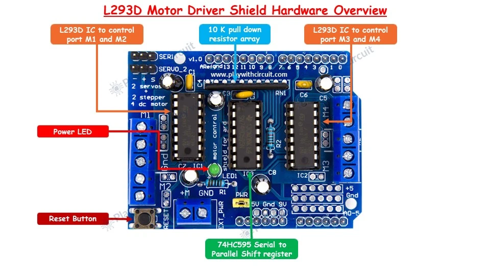
Several components on the shield are important for understanding how it interacts with the Arduino.
L293D Driver ICs
The two L293D ICs are the main motor-driving components on the board. Each IC contains two H-bridge channels. One L293D therefore provides two motor channels, while the two ICs together provide four.
The driver separates the low-current control signals from the higher-current motor outputs. This prevents the Arduino I/O pins from having to drive the motor directly.
74HC595 Shift Register
The shield also contains a 74HC595 serial-in, parallel-out shift register. It is used to expand the available control outputs for the motor driver circuitry.
This arrangement reduces the number of Arduino pins that would otherwise be required to control the direction signals of all the motor channels.
Servo Connectors
Two three-pin servo headers are provided on the board. The first servo connector uses Arduino PWM pin D10, while the second uses PWM pin D9.
This makes connecting a standard hobby servo considerably easier than building a separate servo interface circuit.
Power Circuit
The board provides a motor power connection and a power-selection jumper. Depending on the application, the Arduino and motor supply can either share a supply arrangement or the motors can be powered separately.
When using an external supply through the shield's EXT_PWR connector, the power jumper must be removed to prevent the two supply paths from being connected incorrectly.
L293D Shield Pin Usage
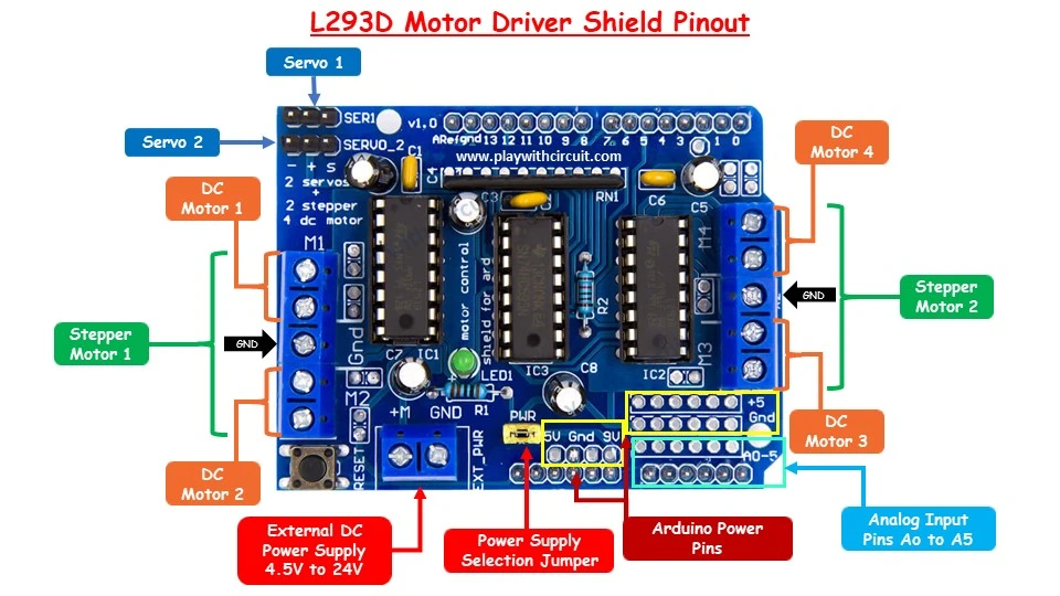
One important consideration when designing a project around this shield is that it occupies a significant number of Arduino UNO pins.
The shield uses:
-
D3
-
D4
-
D5
-
D6
-
D7
-
D8
-
D9
-
D10
-
D11
-
D12
D0 and D1 are normally used for serial communication, while D13 is connected to the Arduino's onboard LED.
This leaves very few conventional digital I/O pins available. For this reason, the analog inputs A0 through A3 can be used as digital inputs when additional buttons or control switches are required.
Motor Output Connections
The four DC motor terminals are labeled M1, M2, M3, and M4.
For a DC motor project, a motor can be connected directly to one of these output terminals. The direction of rotation can then be changed by reversing the polarity applied by the H-bridge.
For stepper motor applications, one stepper can be connected across the M1/M2 channels and another across M3/M4, depending on the motor and shield configuration.
Servo motors use the dedicated servo headers rather than the M1-M4 terminals.
Controlling an SG90 Servo Motor
For this demonstration, we will use a common SG90 5V micro servo with an Arduino UNO and the L293D shield.
The objective is simple: two push buttons are used to move the servo arm in opposite directions, while a potentiometer provides an adjustable input that can be used by the program to control the movement rate.
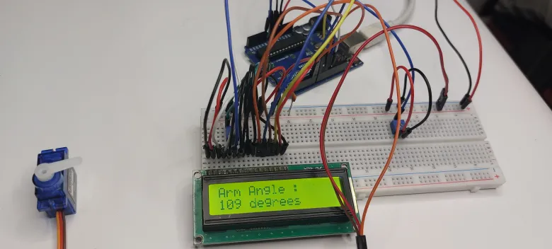
A 16×2 I2C LCD can also be included to display information about the servo's movement.
Hardware Required
-
Arduino UNO R3
-
L293D Motor Driver Shield
-
SG90 5V micro servo
-
10K potentiometer
-
2 push buttons
-
16×2 I2C LCD
-
Breadboard
-
Jumper wires
-
USB cable
Software Required
The project can be developed using the Arduino IDE.
The main libraries required are:
-
Servo library
-
LiquidCrystal I2C library
The Servo library is commonly available with the Arduino development environment, while the I2C LCD library needs to be installed if it is not already present.
Servo Wiring
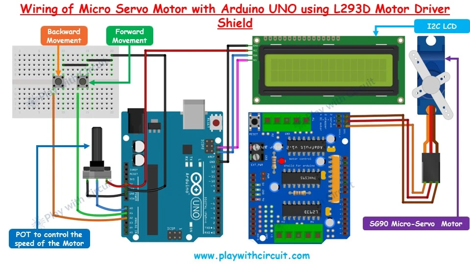
The L293D shield should be mounted on top of the Arduino UNO. If the shield is shown beside the Arduino in a wiring illustration, it is only to make the additional connections easier to see.
The SG90 servo is connected to the first servo header, SERVO_1. The orange signal wire is connected to the shield's D10/PWM connection, while the servo receives 5V and GND through the servo header.
The basic servo connection is:
| Servo connection | L293D shield |
|---|---|
| Signal | SERVO_1 / D10 |
| VCC | 5V |
| GND | GND |
Potentiometer Connection
The 10K potentiometer provides an adjustable analog voltage to the Arduino.
Connect its:
-
Middle pin → A0
-
One outer pin → 5V
-
Other outer pin → GND
Turning the potentiometer changes the voltage measured at A0. The Arduino can use this changing value to determine the servo's movement speed or other motion parameters defined by the program.
Push Button Connections
Because the L293D shield uses most of the Arduino UNO's digital pins, analog inputs are used as digital inputs for the two push buttons.
The connections are:
-
A1 → Forward movement button
-
A2 → Reverse movement button
When the button connected to A1 is pressed, the servo moves in one direction. The A2 button moves it in the opposite direction.
The exact movement range and speed are determined by the Arduino program.
LCD Connections
A 16×2 LCD with an I2C interface can be used to provide visual feedback.
Connect:
-
LCD VCC → Arduino 5V
-
LCD GND → Arduino GND
-
LCD SDA → Arduino SDA
-
LCD SCL → Arduino SCL
The LCD can be used to display information such as movement direction, servo position, or the current speed setting.
How the Servo Control Works
When the Arduino starts, the servo is initialized at its center position. This provides a known starting point instead of allowing the servo to begin from an unpredictable position.
The Arduino continuously monitors the two push buttons. Pressing the forward button causes the servo position to move progressively in one direction. Pressing the reverse button changes the position in the opposite direction.
The potentiometer connected to A0 provides an analog value. The program can convert this value into a suitable movement interval or speed parameter. As the potentiometer is rotated, the servo movement can therefore be made slower or faster.
This is a useful approach for mechanisms where the user needs direct control over the rate of movement rather than simply commanding the servo to jump from one position to another.
Important Power Considerations
A servo motor should not be treated like a simple logic-level peripheral. It can draw considerably more current when starting, changing direction, or operating under mechanical load.
The L293D shield's servo header is powered from the Arduino 5V supply. Therefore, the current requirements of the particular servo should be checked before using this arrangement.
For larger or higher-current servos, a suitable external regulated supply is generally a better approach, with the grounds connected appropriately.
Also avoid connecting an external motor supply while leaving the shield's power-selection jumper configured incorrectly. When the EXT_PWR input is being used according to the shield's external-power configuration, the PWR jumper should be removed.
Extending the Project
The servo example is only one possible application of the L293D shield.
The same hardware can be used to build more advanced motion-control projects. For example, a DC motor can be connected to one of the M1-M4 outputs and controlled for both speed and direction. A 28BYJ-48 5V unipolar stepper motor can also be connected using two motor channels and controlled through the appropriate motor-control library.
This makes the shield particularly useful when experimenting with different motor technologies on the same Arduino platform.
If you want to explore the complete setup for DC motor speed and direction control, servo control, and 28BYJ-48 stepper motor operation, the full L293D motor shield tutorial on Play with Circuit covers those configurations with their corresponding wiring details and example programs.
Conclusion
The L293D Motor Driver Shield provides a convenient way to add motor-control capability to an Arduino UNO without designing a separate driver circuit for every motor type. Its two L293D ICs provide four motor channels, while the dedicated servo headers make hobby servo integration straightforward.
In this project, an SG90 servo was controlled using an Arduino UNO, with push buttons providing directional commands and a potentiometer supplying an adjustable analog input. An I2C LCD can be added to provide useful feedback during operation.
For makers who want to go beyond servo control, the same shield can also be used for DC and stepper motor projects. A complete reference covering those additional configurations, including the wiring and Arduino code, is available in the full L293D Motor Driver Shield and Arduino tutorial on Play with Circuit.