







Story
# Arduino Uno R3 SMD + IMU + BMP280 + 3.3V I²C
## Overview
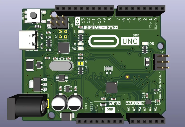
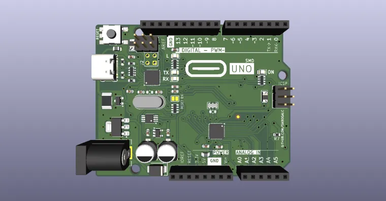
This project is a modified, sensor-integrated version of the **Arduino Uno R3 SMD**, designed specifically for projects where physical space is limited and external sensor breakout boards are inconvenient, bulky, or mechanically difficult to position.
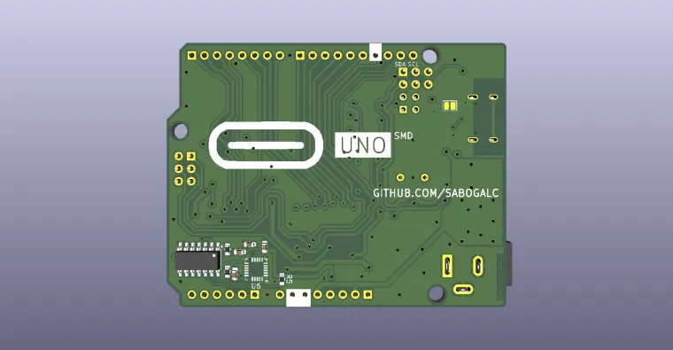
The design integrates an **MPU-6050 6-axis IMU**, a **Bosch BMP280 barometric pressure sensor**, and a dedicated **3.3 V I²C interface with voltage-level translation** directly onto the Arduino Uno PCB.
The fundamental idea behind this project is simple:
> **Instead of adding sensor modules around the Arduino, put commonly required sensors directly onto the Arduino itself.**
In many robotics, mechanical, wearable, experimental, and embedded projects, the electronics are not the only constraint. The physical structure of the project can be even more restrictive.
A robot may have a very small chassis.
A mechanical assembly may have only a narrow electronics compartment.
A wearable project may have very little space available for a controller and several breakout boards.
A moving mechanism may have no convenient location for an external sensor board.
A compact enclosure may have been designed around the Arduino itself, leaving no room for additional modules.
In situations like these, using conventional breakout boards can become surprisingly problematic.
Every additional module requires:
* PCB area
* mounting space
* wires
* connectors
* mechanical clearance
* cable routing
* additional fastening
* additional power connections
* additional points of failure
More importantly, external sensors often cannot be positioned exactly where the application requires them.
That matters particularly for motion sensors.
An IMU does not merely need to communicate electrically with the microcontroller. Its physical orientation and mounting position are part of the measurement system.
If an external IMU breakout is mounted at an awkward angle, on a flexible cable, away from the main PCB, or with an orientation different from the intended coordinate system, the resulting measurements may require additional calibration, coordinate transformation, or mechanical compensation.
This project therefore explores a different approach:
**integrate the sensors into the controller PCB itself while preserving the familiar Arduino Uno form factor and interface.**
---
# Why This Project Exists
## The problem with adding sensors externally
A conventional Arduino Uno project might look something like this:
```text
Arduino Uno
|
+---- jumper wires ---- MPU-6050 breakout
|
+---- jumper wires ---- BMP280 breakout
|
+---- additional wiring ---- other peripherals
```
Electrically, this is perfectly reasonable.
Mechanically, however, it can become a mess.
For a simple breadboard experiment, this does not matter much.
For a compact robot or constrained mechanical project, it can matter enormously.
Imagine building a small robotic mechanism where the entire electronics compartment is only slightly larger than the Arduino PCB.
Adding a separate IMU board means finding another place for the board.
Adding a separate BMP280 means finding yet another place.
The result can quickly turn into:
```text
[ Arduino ]
|
wires
|
[ IMU board ]
|
wires
|
[ BMP280 board ]
```
This consumes space that could otherwise be used for:
* motors
* gears
* batteries
* structural elements
* brackets
* actuators
* mechanical linkages
* wiring channels
* cooling
* protective enclosures
The objective of this project is therefore to **make the Arduino PCB itself the sensor carrier**.
---
# Design Philosophy
The project follows several principles.
### 1. Preserve the Arduino Uno experience
The board remains fundamentally an Arduino Uno-style development board.
The familiar headers remain available, allowing existing Arduino shields, sensors, and accessories to continue being used.
### 2. Integrate frequently useful sensors
Instead of requiring external breakout boards, the PCB itself contains:
* MPU-6050
* BMP280
This turns the Uno into a much more capable sensing platform without requiring additional sensor boards.
### 3. Reduce mechanical footprint
Integrating the sensors eliminates the physical footprint of separate breakout boards.
This is particularly useful for compact robotics and mechanically constrained designs.
### 4. Provide proper 3.3 V interfacing
Many modern sensors operate at 3.3 V rather than 5 V.
The project therefore does not simply connect a 3.3 V sensor directly to a 5 V Arduino I²C bus.
Instead, the design incorporates dedicated level translation.
### 5. Keep the sensor interfaces accessible
The sensors are integrated internally, but the design also provides access to the relevant interfaces through the Arduino headers.
This allows the board to function both as a standalone sensing controller and as a development platform.
---
# Integrated Sensors
## MPU-6050
The first major addition is the **MPU-6050**.
The MPU-6050 combines:
* 3-axis accelerometer
* 3-axis gyroscope
into a single integrated motion-sensing device.
This makes it suitable for applications involving:
* robotics
* orientation sensing
* motion tracking
* balancing robots
* gesture detection
* stabilization
* inertial measurement
* mechanical movement analysis
* experimental control systems
The sensor is connected through I²C.
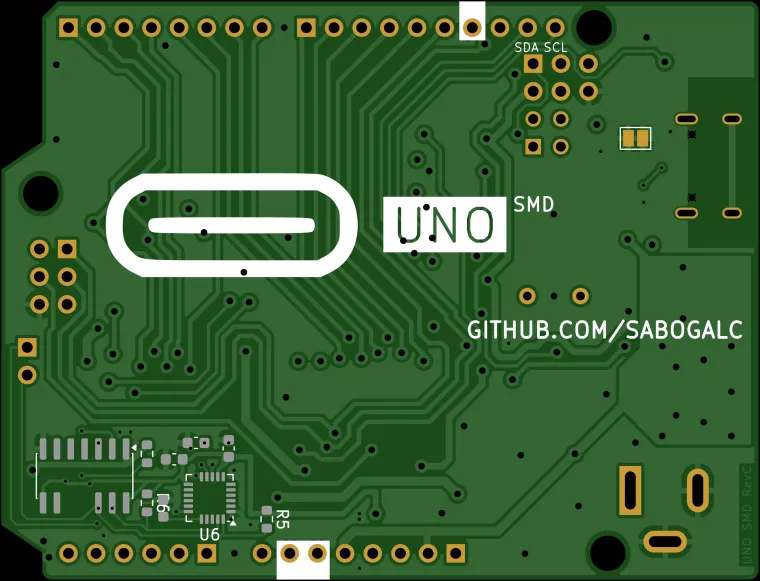
In this project, the MPU-6050 is designated as **U6** in the schematic and BOM.
The BOM specifies an:
```text
MPU-6050
QFN-24
4 mm × 4 mm
```
package.
This is particularly appropriate for the project's space-saving objective because the actual sensor IC occupies dramatically less PCB area than a conventional MPU-6050 breakout module.
---
# BMP280
The second integrated sensor is the **Bosch BMP280**.
The BMP280 is a digital barometric pressure sensor capable of measuring:
* atmospheric pressure
* temperature
Pressure measurements can also be used to estimate relative altitude when combined with an appropriate reference and calculation.
The BMP280 is designated as **U8** in the design.
The BOM specifies the Bosch LGA package:
```text
Bosch LGA-8
2 mm × 2.5 mm
```
This extremely compact package makes the sensor well suited to direct PCB integration.
The BMP280 communicates using I²C in this design.
This gives the Arduino access to another environmental measurement channel without requiring a separate breakout board.
---
# Why Combine an IMU and Barometer?
Combining these sensors makes the board particularly interesting for robotics and experimental motion systems.
The MPU-6050 provides information about:
* acceleration
* angular velocity
* rotational movement
while the BMP280 provides:
* pressure
* temperature
* pressure-derived altitude information
Together, they can be used as a foundation for experiments involving:
* motion tracking
* robotic platforms
* altitude experiments
* vertical movement detection
* balancing systems
* autonomous vehicles
* drones and flight experiments
* mechanical motion analysis
* sensor fusion experiments
The sensors measure fundamentally different physical quantities, which makes the combination significantly more useful than either sensor alone.
---
# 3.3 V I²C Interface
One of the important parts of this design is the integrated **3.3 V I²C interface**.
The Arduino Uno is traditionally associated with a 5 V ATmega328P system.
Many modern sensors and peripherals, however, use 3.3 V logic.
Simply connecting a 3.3 V sensor to a 5 V I²C bus is therefore not something that should be done casually.
This project addresses that problem with a dedicated level translator.
The BOM identifies:
```text
U7 = TXS0104ED
```
as the voltage-level translation device.
The schematic uses separate sensor-side I²C nets:
```text
MPU_SDA
MPU_SCL
```
and the corresponding translated connection is routed toward the Arduino-side I²C interface.
This allows the board to maintain compatibility between the Arduino's logic environment and the lower-voltage sensor domain.
---
# Why Level Translation Matters
I²C is slightly different from an ordinary unidirectional digital signal.
SDA and SCL are open-drain/open-collector style bus signals and rely on pull-up resistors.
That means a proper voltage-domain interface is important.
The project therefore includes dedicated circuitry rather than simply relying on software or hoping that the voltage levels will be acceptable.
This is especially useful when the board is used as a platform for additional 3.3 V peripherals.
The design also contains dedicated 3.3 V power circuitry.
The BOM identifies:
```text
U2 = LP2985-3.3
```
as the 3.3 V regulator.
This creates a dedicated low-voltage supply domain for the 3.3 V electronics.
---
# Integrated Architecture
At a high level, the board can be thought of as several interconnected domains:
```text
┌─────────────────────┐
│ USB Type-C │
└──────────┬──────────┘
│
▼
┌─────────────────────┐
│ Arduino Uno │
│ │
│ ATmega328P │
│ │
└──────────┬──────────┘
│
Arduino I²C
│
┌──────▼──────┐
│ TXS0104ED │
│ Level │
│ Translator │
└──────┬──────┘
│
3.3 V I²C
│
┌───────────┴───────────┐
│ │
┌─────▼─────┐ ┌─────▼─────┐
│ MPU-6050 │ │ BMP280 │
│ │ │ │
│ Accel │ │ Pressure │
│ Gyro │ │ Temp │
└───────────┘ └───────────┘
```
This architecture allows the sensor subsystem to remain physically integrated into the Arduino PCB while still maintaining an appropriate 3.3 V electrical domain.
---
# Arduino Uno Core
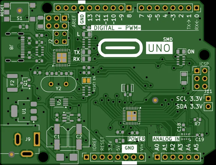
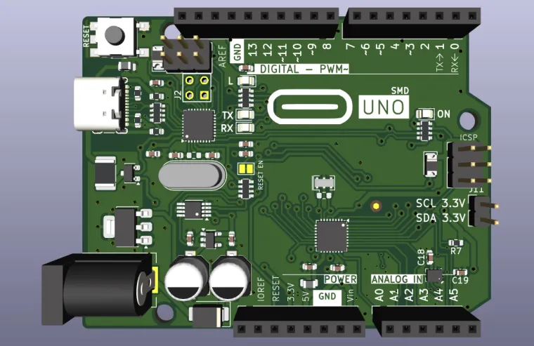
The project retains the essential architecture of the Arduino Uno SMD design.
The BOM includes:
```text
ATMEGA328P-MU
```
as the primary microcontroller.
The USB interface is handled by:
```text
ATMEGA16U2-MU
```
The project therefore retains the familiar Arduino USB-to-microcontroller architecture rather than replacing the Arduino ecosystem with an entirely different controller.
This is important because the goal is not to create an entirely new development board.
The goal is to create a **more capable physical implementation of the familiar Arduino Uno platform**.
---
# USB Type-C
Another notable hardware modification is the use of a **USB Type-C connector**.
The BOM specifies:
```text
USB_C_Receptacle_USB2.0_16P
```
for the USB connector.
This provides a modern physical USB interface while retaining USB 2.0 connectivity.
The combination of:
* USB Type-C
* ATmega16U2
* ATmega328P
* Arduino-compatible headers
keeps the board familiar from a software and development perspective while modernizing the physical implementation.
---
# SMD Construction
The project uses an SMD-oriented implementation rather than relying on large through-hole components for the core electronics.
Several important ICs use compact packages, including:
| Component | Package |
| ---------- | -------- |
| ATmega328P | VQFN-32 |
| ATmega16U2 | VQFN-32 |
| MPU-6050 | QFN-24 |
| BMP280 | LGA-8 |
| TXS0104ED | SOIC-14 |
| LP2985 | SOT-23-5 |
| LMV358 | MSOP-8 |
This contributes significantly to the board's compactness.
It also makes the design more appropriate for automated PCB assembly.
---
# Why Integrate the Sensors Instead of Using Breakout Boards?
This is arguably the central motivation behind the project.
A breakout board is excellent for experimentation.
It is convenient.
It provides accessible pins.
It is easy to replace.
But breakout boards are not always ideal for a finished mechanical system.
Consider a small robot.
The robot may have a carefully designed frame where every millimeter matters.
A separate sensor PCB can create problems such as:
```text
Additional PCB
↓
Additional mounting
↓
Additional screws
↓
Additional wires
↓
Additional connectors
↓
Additional mechanical volume
```
Integrating the sensors turns that entire chain into a much simpler system:
```text
Arduino PCB
│
├── MPU-6050
│
└── BMP280
```
The sensors effectively become part of the controller.
---
# Mechanical Constraints and Calibration
Mechanical constraints are particularly important for IMUs.
An accelerometer and gyroscope measure motion relative to their own physical coordinate system.
Therefore, the orientation of the sensor relative to the robot or mechanism matters.
With a separate breakout board, the sensor may end up:
* rotated
* tilted
* mounted upside down
* positioned far from the controller
* attached using wires
* mounted on an uneven mechanical surface
All of these can complicate calibration and interpretation of the sensor data.
For example, an IMU intended to measure a robot's X/Y/Z axes should ideally have a clearly defined physical relationship with those axes.
If the breakout board is mounted at an arbitrary angle, software may need to compensate for that orientation.
Integrating the sensor into the main PCB provides a **known mechanical reference**.
The PCB itself becomes the mechanical reference plane for the sensor.
This does not magically eliminate calibration. Real sensors still have offsets, scale errors, temperature effects, manufacturing tolerances, and other error sources.
However, it can eliminate one major source of uncertainty:
**the sensor's mechanical relationship with the rest of the electronics.**
That makes the design particularly useful for projects where repeatable physical geometry matters.
---
# Space-Constrained Robotics
This board is especially relevant to compact robotics.
For example:
### Small balancing robot
The MPU-6050 can provide acceleration and angular-rate information without requiring a separate IMU PCB.
### Compact rover
The Arduino can remain the main controller while the integrated IMU provides motion information.
### Robotic arm
The integrated motion sensor can be used for experimentation involving orientation and movement.
### Wearable device
Removing external sensor boards reduces the amount of hardware that needs to fit inside an enclosure.
### Small autonomous vehicle
The IMU and barometer can provide additional environmental and motion information without expanding the PCB footprint.
### Mechanical experiment
A designer can place the entire controller and sensing system into a constrained mechanical assembly.
---
# External I²C Expansion
An important design philosophy of the board is that integrating sensors should **not** mean sacrificing expandability.
The Arduino's normal interfaces remain available.
The board exposes the Arduino-style headers, allowing additional external hardware to be connected.
The integrated sensors therefore act as built-in peripherals rather than replacing the expansion capability of the Uno.
This makes the board useful in two modes:
### Standalone sensing platform
```text
Arduino
+ MPU-6050
+ BMP280
```
No external sensor boards required.
### Expandable development platform
```text
Arduino
+ MPU-6050
+ BMP280
+ external I²C devices
+ external SPI devices
+ external UART devices
+ shields
```
This makes the integrated sensors an addition to the platform rather than a restriction.
---
# Power Architecture
The project retains the traditional Arduino power architecture while incorporating the additional 3.3 V sensor domain.
The BOM contains:
* NCP1117-5.0
* LP2985-3.3
* capacitors for local decoupling
* ferrite filtering
* protection components
* USB power input
* barrel-jack input
The 3.3 V rail is specifically used by the low-voltage sensor circuitry.
The design therefore has both:
```text
5 V domain
```
and
```text
3.3 V domain
```
with the voltage translator providing the interface between the relevant logic domains.
---
# Protection and Supporting Components
The design is not simply the microcontroller and sensors.
The BOM contains a range of supporting components required for a functional Arduino board, including:
* reset circuitry
* USB circuitry
* power filtering
* decoupling capacitors
* pull-up resistors
* indicator LEDs
* protection components
* ferrite elements
* connectors
* clock components
Examples include:
```text
MF-MSMF050-2
FDN340P
LMV358IDGKR
CD1206-S01575
CGRB307-G
```
along with multiple resistor and capacitor networks.
These components form the supporting infrastructure around the Arduino and sensor subsystem.
---
# PCB Connectivity
The project retains the standard Arduino-style connector arrangement.
The design contains:
* 1 × 10-pin header
* 2 × 8-pin headers
* 1 × 6-pin header
* 2 × 3-pin headers
* USB Type-C
* barrel-jack power input
This means the board can still be treated like an Arduino Uno from a hardware-integration perspective.
The integrated sensors simply add functionality behind the familiar connector layout.
---
# Design Files
The repository contains the KiCad design data necessary to inspect and work with the project.
The main project includes:
```text
Arduino Uno SMD.kicad_sch
Arduino Uno SMD.kicad_pro
Arduino Uno SMD.kicad_sym
Power.kicad_sch
Headers.kicad_sch
ATMEGA328P-MU.kicad_sch
production/bom.csv
production/netlist.ipc
```
The design is therefore not merely a conceptual rendering.
It contains the underlying schematic and manufacturing-oriented information needed to continue development of the PCB.
---
# Bill of Materials Highlights
The project's BOM identifies the major integrated components as follows:
| Reference | Component | Purpose |
| --------- | ------------------ | --------------------------------- |
| U3 | ATMEGA16U2-MU | USB interface / USB communication |
| U4 | ATMEGA328P-MU | Main Arduino microcontroller |
| U6 | MPU-6050 | 6-axis IMU |
| U7 | TXS0104ED | Logic-level translation |
| U8 | BMP280 | Barometric pressure + temperature |
| U2 | LP2985-3.3 | 3.3 V regulation |
| U5 | LMV358IDGKR | Analog/support circuitry |
| Y1 | CSTNE16M0V530000R0 | ATmega328P clock source |
| Y2 | LFXTAL003240BULK | USB MCU clock source |
The BOM also includes the connector, protection, filtering, resistor, capacitor, LED, and power components required for the complete board.
---
# Sensor Data Architecture
Conceptually, the sensor system looks like:
```text
Arduino ATmega328P
│
│ I²C
▼
┌──────────────┐
│ TXS0104ED │
│ Level Shift │
└──────┬───────┘
│
3.3 V I²C
┌─────┴─────┐
│ │
▼ ▼
MPU-6050 BMP280
│ │
┌─────┴─────┐ ┌─┴──────┐
│ │ │ │
Accelerometer Gyro Pressure Temperature
```
This gives the software a unified way to communicate with the integrated sensing subsystem.
---
# Calibration Considerations
Although integrating the sensors reduces mechanical uncertainty, calibration remains important.
For the MPU-6050, calibration may involve:
* accelerometer offset calibration
* gyroscope offset calibration
* axis alignment
* scale-factor correction
* temperature compensation where required
For the BMP280, pressure readings depend on:
* atmospheric conditions
* reference pressure
* temperature
* sensor characteristics
* physical installation
Therefore, this board should not be interpreted as a "zero-calibration" sensor platform.
Instead, the objective is to create a **mechanically consistent sensing platform that is easier to calibrate and integrate into a project**.
That distinction is important.
---
# Why This Is Useful for Physical Projects
Software projects often have effectively unlimited virtual space.
Mechanical projects do not.
A software developer can add another library.
A PCB designer can sometimes add another component.
A mechanical designer cannot simply add another 20 mm of space.
Physical constraints are absolute.
That makes PCB-level integration particularly valuable.
By integrating commonly required sensors directly into the Arduino PCB, this project attempts to shift functionality from:
```text
Arduino + modules + wires + mounts
```
toward:
```text
single integrated controller PCB
```
This can simplify both the electrical and mechanical architecture of a project.
---
# Intended Applications
This board can be useful for:
* robotics
* compact robots
* balancing robots
* autonomous vehicles
* mechanical experiments
* wearable electronics
* motion sensing
* orientation experiments
* educational projects
* sensor-fusion experiments
* altitude experiments
* embedded prototyping
* compact IoT devices
* custom Arduino-based instruments
It is particularly suited to projects where the physical arrangement of electronics matters as much as the electrical design.
---
# What Makes This Variant Different?
A normal Arduino Uno provides the computing and I/O platform.
This variant adds an integrated sensing layer.
Instead of:
```text
Arduino Uno
+
MPU-6050 module
+
BMP280 module
+
level shifter
+
extra wiring
```
the project attempts to consolidate the system into:
```text
┌───────────────────────────────────┐
│ │
│ Arduino Uno PCB │
│ │
│ ┌─────────┐ ┌─────────┐ │
│ │ MPU-6050│ │ BMP280 │ │
│ └─────────┘ └─────────┘ │
│ │
│ 3.3 V I²C circuitry │
│ │
│ ATmega328P + ATmega16U2 │
│ │
│ USB Type-C │
│ │
└───────────────────────────────────┘
```
The result is a controller that can be dropped into a project with sensing capabilities already built in.
---
# Design Heritage and Credits
This project is based on and modifies the **Arduino Uno SMD** design work from:
**sabogalc / Carlos Sabogal**
Original project:
**KiCad-Arduino-Boards**
The original repository contains KiCad recreations of Arduino boards, including the Arduino Uno R3 SMD design.
The files in this project were **modified from the original `sabogalc/KiCad-Arduino-Boards` design** to create this sensor-integrated variant.
The modifications in this project include, among other things:
* integrating the MPU-6050
* integrating the BMP280
* adding the 3.3 V sensor power domain
* adding I²C voltage-level translation
* modifying the schematic and PCB design for the integrated sensors
* adapting the design for the intended space-constrained applications
* updating the manufacturing/BOM information for the additional components
The original design work by **sabogalc** is therefore an important part of the project's design lineage and is explicitly credited here.
Please refer to the original repository for the original Arduino Uno SMD implementation:
[sabogalc/KiCad-Arduino-Boards](https://github.com/sabogalc/KiCad-Arduino-Boards?utm_source=chatgpt.com)
---
# Attribution
A major portion of the underlying Arduino Uno SMD structure originates from the work of **Carlos Sabogal (`sabogalc`)**.
This project should therefore be understood as a **modified derivative design**, rather than an entirely independent recreation of the Arduino Uno SMD board.
Credit:
> **Original Arduino Uno SMD design:** Carlos Sabogal (`sabogalc`)
> **Original repository:** `sabogalc/KiCad-Arduino-Boards`
> **This variant:** modified to integrate MPU-6050, BMP280, and 3.3 V I²C functionality.
The original repository itself describes its collection as including Arduino Uno R3, Arduino Uno R3 SMD, Arduino Uno R4 variants, Leonardo, Micro, and other Arduino board designs.
---
# Project Philosophy
This project is ultimately about a small but important idea:
## Don't make the mechanical system adapt to the electronics when the electronics can adapt to the mechanical system.
A conventional development workflow often looks like:
```text
Choose Arduino
↓
Add sensor breakout
↓
Add another sensor breakout
↓
Find somewhere to mount them
↓
Route wires
↓
Secure boards
↓
Deal with orientation
↓
Calibrate everything
```
This project reverses part of that process:
```text
Design the controller
↓
Integrate commonly required sensors
↓
Define the sensor orientation
↓
Provide proper voltage domains
↓
Expose standard Arduino interfaces
↓
Install the complete board into the project
```
The result is not intended to replace every Arduino breakout board.
Instead, it provides another option for projects where **integration, physical size, wiring reduction, and repeatable sensor placement** are important.
---
# Current Hardware Summary
### Microcontroller
* ATmega328P-MU
* Arduino Uno architecture
* SMD implementation
### USB
* ATmega16U2-MU
* USB 2.0
* USB Type-C connector
### Motion sensing
* MPU-6050
* 3-axis accelerometer
* 3-axis gyroscope
* I²C interface
### Environmental sensing
* Bosch BMP280
* Barometric pressure sensing
* Temperature sensing
* I²C interface
### Logic translation
* TXS0104ED
* Used for interfacing between the Arduino-side and 3.3 V sensor-side I²C domains
### 3.3 V power
* LP2985-3.3 regulator
### Expansion
* Standard Arduino-style headers
* External peripheral connectivity retained
---
# Conclusion
The **Arduino Uno R3 SMD + IMU + BMP280 + 3.3 V I²C** project is an experiment in turning a familiar Arduino Uno into a more physically integrated embedded platform.
The project addresses a practical problem encountered in compact electronics and robotics:
**external sensor modules consume physical space and can introduce mechanical placement and calibration complications.**
By integrating an MPU-6050 and BMP280 directly onto the Arduino PCB, the sensing hardware becomes part of the controller itself.
The integrated 3.3 V power domain and TXS0104ED level translation provide the electrical infrastructure needed to interface the lower-voltage sensors with the Arduino architecture.
At the same time, the traditional Arduino headers, USB connectivity, and ATmega328P-based architecture remain available, keeping the platform familiar and expandable.
The result is a board intended for projects where every millimeter matters, where sensor orientation should be mechanically predictable, and where reducing external modules and wiring can make the difference between a convenient prototype and a practical embedded system.
---
## Credits
**Original Arduino Uno SMD design:**
Carlos Sabogal (`sabogalc`)
**Original repository:**
`https://github.com/sabogalc/KiCad-Arduino-Boards`
**Modified project:**
Kaustubh / `kaustubh850`
**Modified repository:**
`https://github.com/kaustubh850/ArduinoEquipped`
This project is a modified derivative of the original Arduino Uno SMD design and is intended to preserve attribution to the original designer while extending the hardware for integrated motion and environmental sensing.