1 Introduction to CrowPanel-Advance-HMI Screen Version 1.1
1.1 product overview
The CrowPanel-ESP32 Advance HMI Display product is divided into 6 sizes, namely 7.0 inches, 5.0 inches, 4.3 inches, 3.5 inches, 2.8 inches, and 2.4 inches.Its main control chip uses ESP32-S3 as the core of the man-machine interface.
The resolution of the 7.0-inch display screen is 800 * 480, the screen driver chip is SC7277, and the touch driver chip is GT911;
5.0-inch display screen resolution of 800 * 480, screen driver chip ST7262, touch driver chip GT911;
4.3-inch display screen resolution of 800 * 480, screen driver chip ST7265, touch driver chip GT911;
3.5-inch display screen resolution of 320 * 480, screen driver chip ILI9488, touch driver chip GT911;
2.8-inch display screen resolution of 240 * 320, screen driver chip ST7789, touch driver chip FT6336U;
2.4-inch display screen with a resolution of 240 * 320, screen driver chip ST7789, and touch driver chip FT6336U.

which combines powerful processing capabilities, diverse peripheral interfaces, and excellent low-power performance. Its integrated 2.4GHz Wi Fi and Bluetooth 5 (LE), combined with the module's built-in RF antenna, ensure the stability of wireless connection, especially suitable for HMI application scenarios with high requirements for wireless connection.
1.2 Hardware feature
After understanding the optimization of the product, let's take a closer look at the hardware changes.
For 4.3-inch, 5.0-inch, and 7.0-inch screens, they only have one USB interface that can be used for code burning, etc.
For 2.4-inch, 2.8-inch, and 3.5-inch, there are two USB ports here. When using the USB port for code burning, you need to first hold down the BOOT button, then press the RESET button, and then release them together to burn the code; The UART0 interface allows for direct code burning without the need to press any buttons.
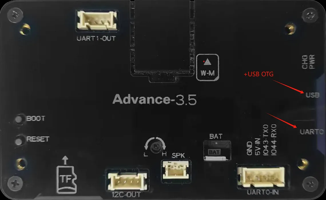
Attention: For the three sizes of 2.4 inches, 2.8 inches, and 3.5 inches, USB OTG function is also available.
The USB OTG function of ESP32-S3 supports switching between host and device roles, allowing for the connection of peripherals such as keyboards, mice, USB drives, or as USB peripherals (such as virtual serial ports, HID devices) to communicate with the host. It is suitable for scenarios such as data transmission, peripheral control, debugging interfaces, custom USB devices, etc. It has high flexibility and simplifies IoT and embedded development.
For 3.5-inch, 4.3-inch, 5.0-inch, and 7.0-inch products, RTC circuits have been added to ensure the continuity and accuracy of system time in the event of a power outage, providing a reliable time reference for data recording and event monitoring.
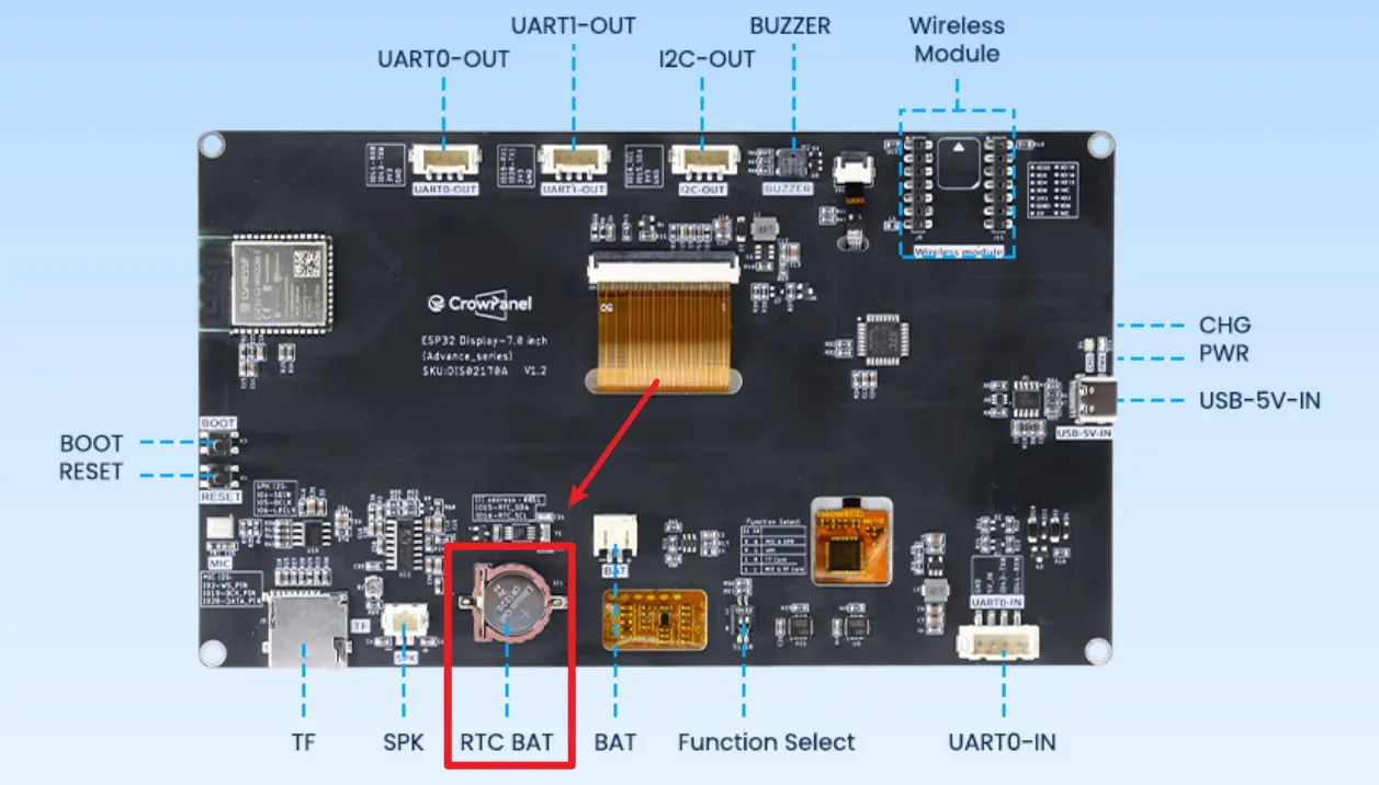
Secondly, this wireless module can be used for communication and data transmission. It supports 802.11 a/b/g/n wireless communication standards, WiFi in the 2.4GHz frequency band, as well as low-power Bluetooth and Bluetooth 5.0, and also supports Zigbee NBIOT、LoRa、UWB、NF2401。
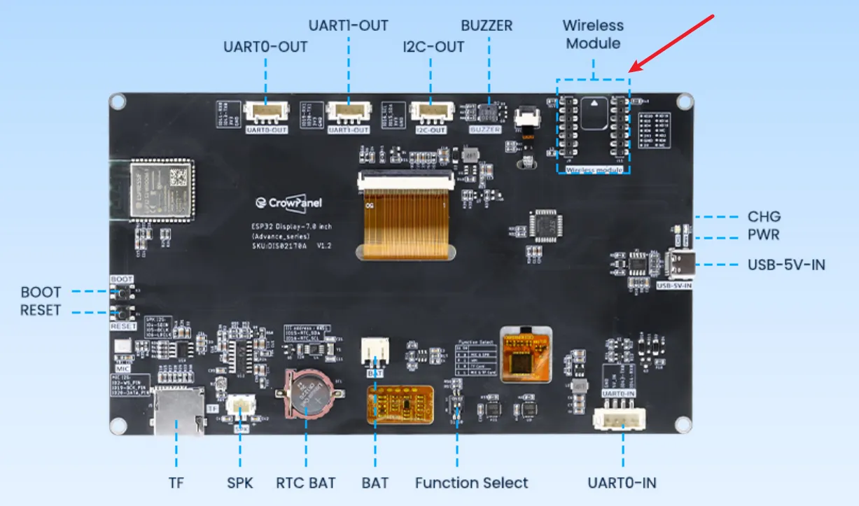
There are also some other interfaces and peripherals available for everyone to use. For example, the I2C interface can be used for sensor devices suitable for using I2C communication; UART0 interface, suitable for sensor devices that use serial communication; SD card slot, capable of meeting local storage requirements; Speaker interface, capable of connecting external speakers for playing songs, etc; Battery interface, which can be used for external battery power supply.
2 Environment configuration
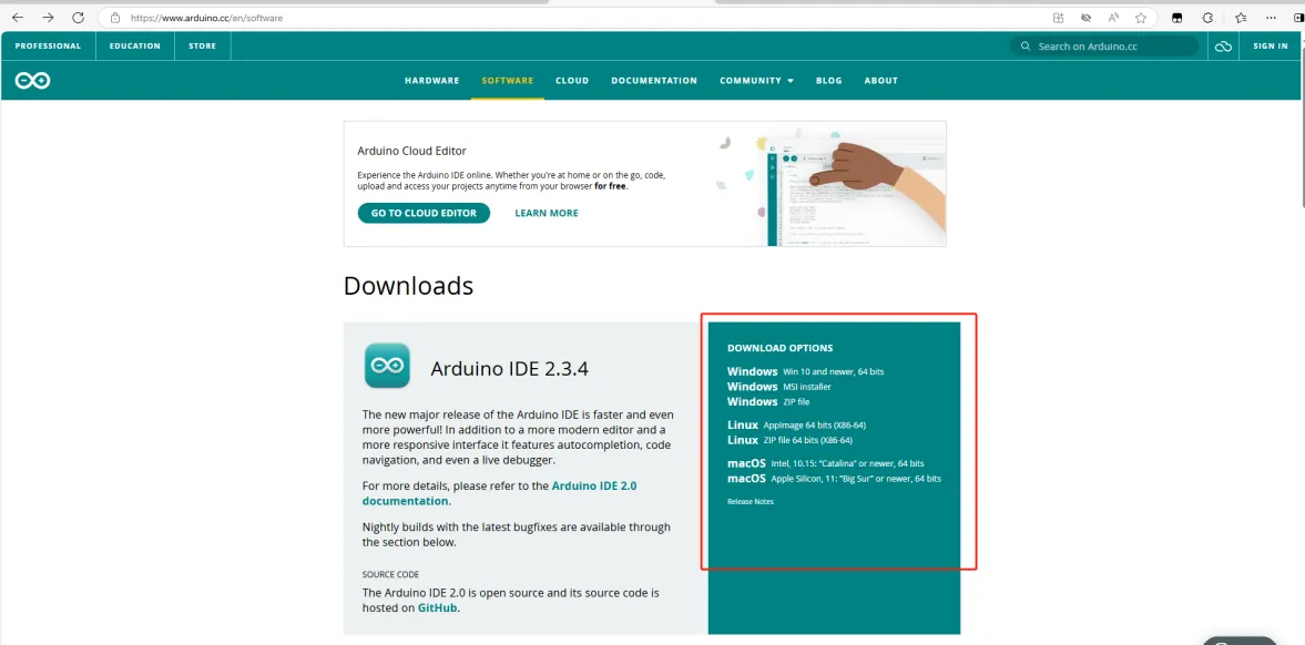
2.1 Open the official Arduino website
https://www.arduino.cc/en/software
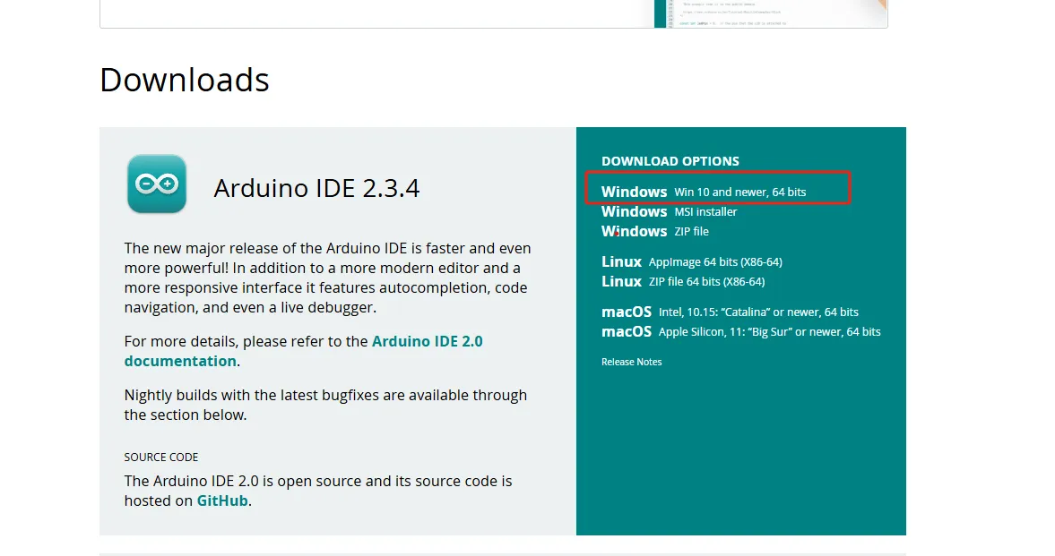
2.2 Choose the appropriate system for installation based on your system
2.2.1 I have chosen the first one here
2.2.2 Choose to download only
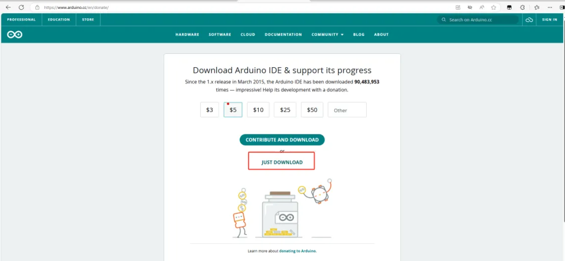
2.2.3 ditto

2.2.4 Waiting for download to complete
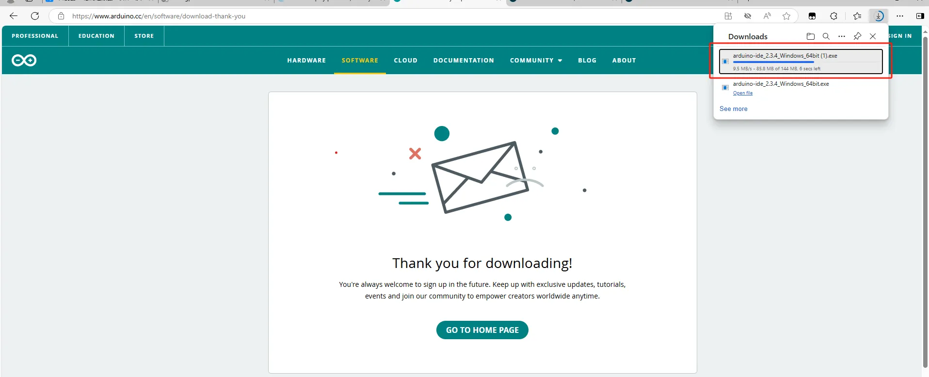
2.3 Confirm the download process
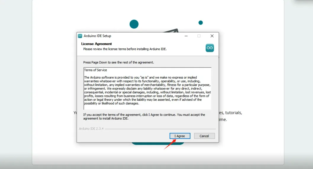
2.3.1 Agree option
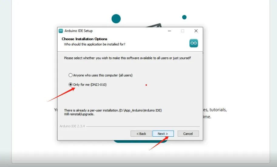
2.3.2 As shown in the figure, confirm
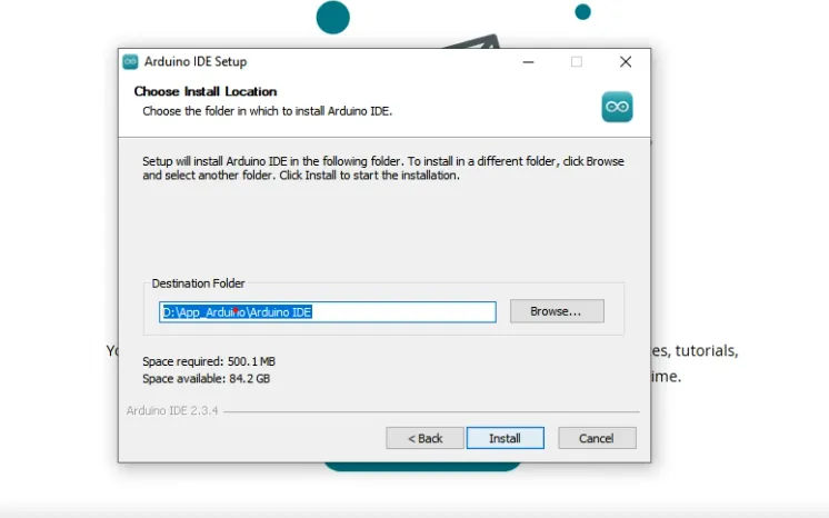
2.3.3 Customize your path and click install
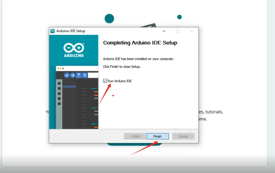
2.3.4 After installation, you can run the Arduino IDE
3 Install ESP32 development board version 3.0.2
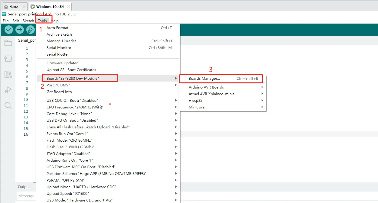
3.1 Open Development Board Management
Path: Tools ->Board ->Board Manager or press Ctrl+Shift+B directly
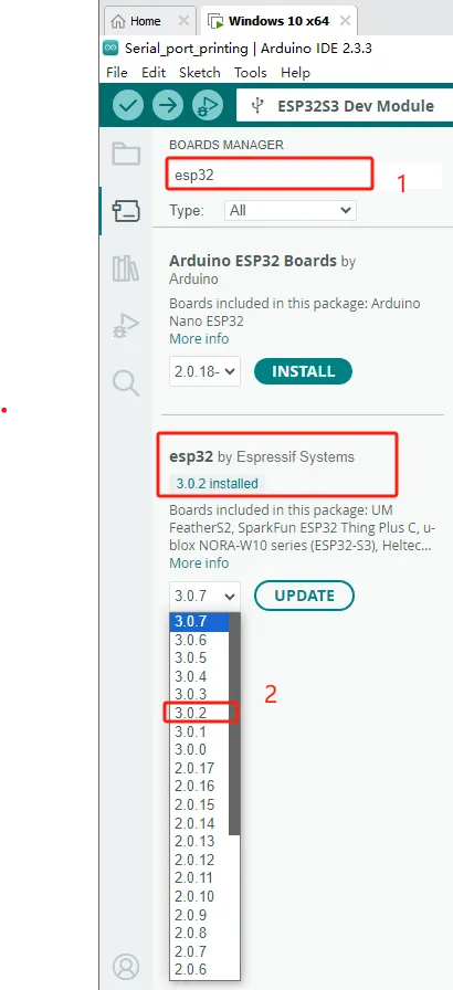
3.2 Search for ESP32 and download it (the version we were using for development at the time was 3.0.2)
3.3 After completing the Esp32 download, replace the files in that directory
3.3.1 Open the "ESP32S3_120M" file we provided, copy a copy of the file from that folder to the following path in ESP32, and replace it
Path reference:
C:\ESP32_Code\CrowPanel_Advanced_HMI\ESP32S3_120M(1)\ESP32S3_120M
C:\Users\14175\AppData\Local\Arduino15\packages\esp32\tools\esp32-arduino-libs\idf-release_v5.1-bd2b9390ef

Note: "ESP32S3_120M" is a recompiled official file that has enabled PSRAM high-speed communication mode, and the improved refresh rate is just one of its optimizations. If not replaced, the maximum can only reach 80M, and after replacement, the maximum is 120M.
3.4 Enter the following code
This case code only requires the use of Advance HMI series board and serial port cable.
It is possible to print Hello World every second through a serial port tool.
int counter = 0; // Define a counter variable
void setup() {

 Serial.begin(9600); // Initialize serial communication

}


void loop() {

 // Print "Hello, World!" and the value of the counter

 Serial.print("Hello, World! "); // Print "Hello, World!"

 Serial.print("--- "); // Add space between "Hello, World!" and the number

 Serial.println(counter); // Print the value of the counter


 counter++; // Increment the counter

 delay(1000); // Output every 1 second

}
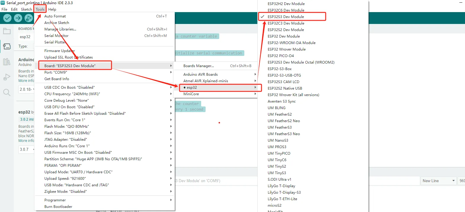
3.5 Configure the burning environment
3.5.1 Select development board
Path:Tools->Board->esp32->ESP32S3 Dev Module
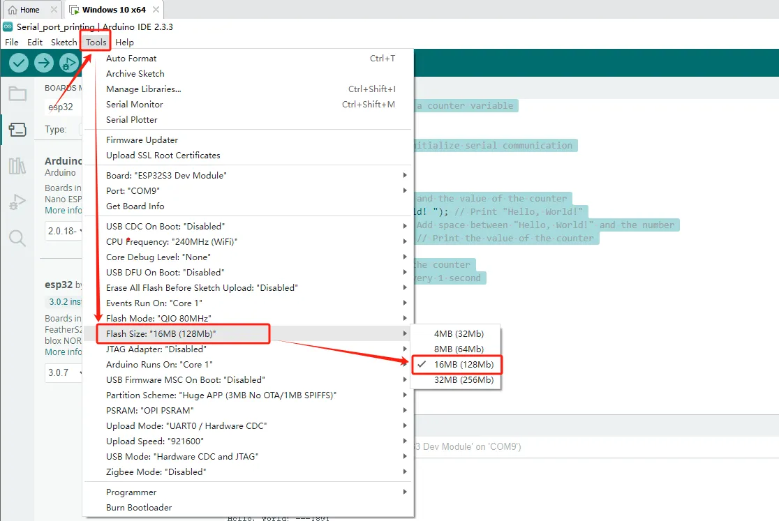
3.5.2 Select Flash Size
Path:Tools->Flash Size->16MB(128Mb)
3.5.3 Select Partition Scheme
Path:Tools->Partition Scheme->Huge APP (3MB No OTA/1MB SPIFFS)

3.5.4 Select PSRAM
Path:Tools->PSRAM->OPI PSRAM

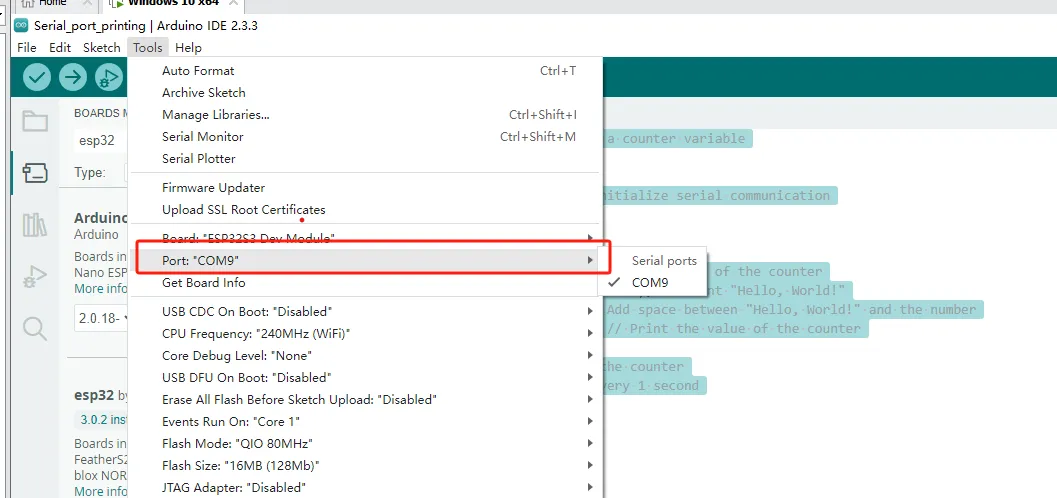
3.5.5 Finally, choose the serial port number you are using
Path:Tools->Port->(The port number you are using yourself)
3.6 Burn code

3.7 Wait for the burning to complete, open the serial port tool, and observe that Hello World is printed every second

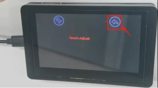
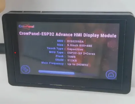
Attention: After powering on the screen, you may see an interface displaying relevant information about the product
If needed, you can perform touch calibration in the lower left corner. (The product has already been calibrated when it leaves the factory)
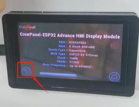
Then, click on the icon in the upper left corner to calibrate
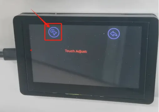
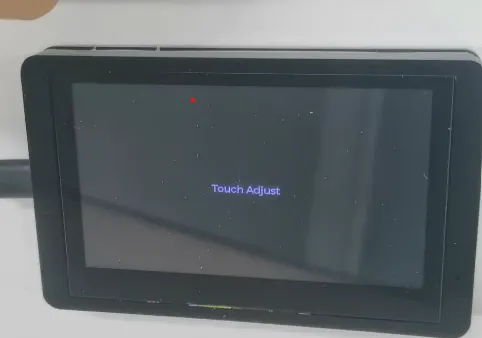
After calibration is completed, simply return