CrowPanel Advance 4.3-HMI ESP32 AI Display
Model DIS01943A

Version 1.0
Pin Output:
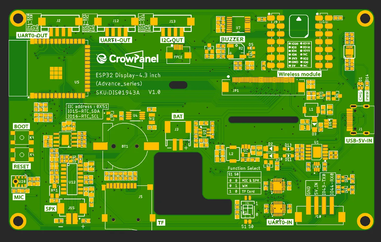
Functional description of the product's internal interfaces:
| Pin Name | Description | Connector Type |
|---|---|---|
| SPK | Output audio signals to connect to speakers. The main board comes with a power amplifier chip circuit. | PH2.0-2P |
| PWR | Power LED. | |
| RST | Reset button. Press it to reset the system. | |
| boot | ||
| UART0-OUT | Builds communication between Logic modules, including the serial communication module and the print module. | HY2.0-4P |
| UART1-OUT | Builds communication between Logic modules, including the serial communication module and the print module. | HY2.0-4P |
| UART0-IN | Input power supply and serial communication functionality | XH2.54-4P |
| I2C-OUT | Establish communication between the microcontroller and peripheral devices. | HY2.0-4P |
| BAT | Connect the lithium battery. (with battery charging circuit)(Input voltage: 3.7–4.2 V) | PH2.0-2P |
Product External Interface Functions:
| 4.3-inch HMI port | pin number | Electrical Characteristics |
|---|---|---|
| UART0-OUT | RX(IO44); TX(IO43) RX; | Output voltage: 3.3V Output current: 1A max. Use: Power supply output and communication. |
| UART1-OUT | RX(IO19); TX(IO20) RX; | Output voltage: 3.3V Output current: 1A max. Use: Power supply output and communication. |
| UART0-IN | RX(IO44); TX(IO43) RX; | Input voltage: 5V ± 5%. 5.5V max. Input current: 2A max. Purpose: Power supply input and communication. |
| I2C | SDA(IO15); SCL(IO16) ; | Output voltage: 3.3V Output current: 1A max. Use: Power supply output and communication. |
| SPK | I2S_LRCLK(IO6);I2S_BCLK(IO5);I2S_SDIN(IO4); | Maximum output current: 20mA Signal type: 3.3V logic level, digital control signal |
| SD Card Slot | MOSI(IO6); MISO(IO4); CLK(IO5); CS(3.3V) | Maximum output current: 20mA Signal type: 3.3V logic level, digital control signal |
| LCD Backlight | PCA9557PW-IO1 | Maximum output current: 20mA Signal type: 3.3V logic level, digital control signal |
| I2S MIC | MIC_SD(IO20);MIC_WS(IO2);MIC_CLK(IO19) | Maximum output current: 20mA Signal type: 3.3V logic level, digital control signal |
| BUZZER | IO8 | Maximum output current: 20mA Signal type: 3.3V logic level, digital control signal |
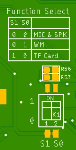
Switching Function Keys:
| S1 | S0 | effective function |
|---|---|---|
| 0 | 0 | MIC&SPK |
| 0 | 1 | WM(wireless module) |
| 1 | 0 | TF Card |
Schematic:
ESP32-S3 and ISP Display Wiring Pins:

ESP32-S3 and Touch Driver Wiring:
i2c address: 0x5D.

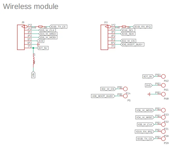
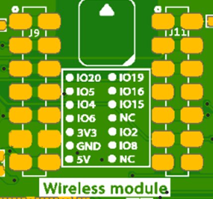
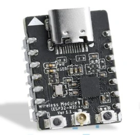
ESP32-S3 and wireless module wiring pins:
Schematic diagram of function selection:
Switching Function Keys:
| S1 | S0 | effective function |
|---|---|---|
| 0 | 0 | MIC&SPK |
| 0 | 1 | WM(wireless module) |
| 1 | 0 | TF Card |
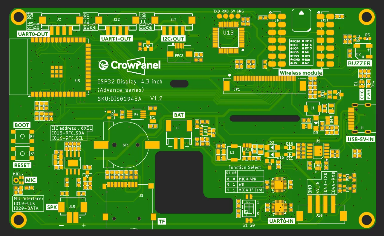
Version 1.1
| 4.3-inch HMI port | pin number | Electrical Characteristics |
|---|---|---|
| UART0-OUT | RX(IO44); TX(IO43) RX; | Output voltage: 3.3V Output current: 1A max. Use: Power supply output and communication. |
| UART1-OUT | RX(IO19); TX(IO20) RX; | Output voltage: 3.3V Output current: 1A max. Use: Power supply output and communication. |
| UART0-IN | RX(IO44); TX(IO43) RX; | Input voltage: 5V ± 5%. 5.5V max. Input current: 2A max. Purpose: Power supply input and communication. |
| I2C | SDA(IO15); SCL(IO16) ; | Output voltage: 3.3V Output current: 1A max. Use: Power supply output and communication. |
| SPK | I2S_LRCLK(IO6);I2S_BCLK(IO5);I2S_SDIN(IO4); | Maximum output current: 20mA Signal type: 3.3V logic level, digital control signal |
| SD Card Slot | MOSI(IO6); MISO(IO4); CLK(IO5); CS(3.3V) | Maximum output current: 20mA Signal type: 3.3V logic level, digital control signal |
| LCD Backlight_PWR | P3.5(STC8H1K28) | Maximum output current: 20mA Signal type: 3.3V logic level, digital control signal |
| Backlight Adjustment | P1.1(STC8H1K28) | |
| I2S MIC | MIC_SD(IO20);MIC_CLK(IO19) | Maximum output current: 20mA Signal type: 3.3V logic level, digital control signal |
| BUZZER | P2.7(STC8H1K28) | Maximum output current: 20mA Signal type: 3.3V logic level, digital control signal |
| TP_RST | P1.7(STC8H1K28) | |
| power amplifier SHUT | P3.6(STC8H1K28) |
Switching Function Keys:
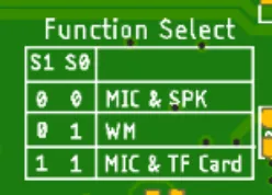
| S1 | S0 | effective function |
|---|---|---|
| 0 | 0 | MIC&SPK |
| 0 | 1 | WM(wireless module) |
| 1 | 1 | MIC&TF Card |
ESP32-S3 and wireless module wiring pins:
Version 1.1
① Version 1.3 introduces an updated backlight control function. In this iteration, the backlight is managed by the STC8H1K28 microcontroller. The programme illuminates the backlight by transmitting numerical values to the microcontroller's address (0x30). Brightness adjustment spans 0-245 levels, where 0 denotes maximum brightness, 244 represents minimum brightness, and 245 disables the backlight.
The buzzer control principle mirrors that of the backlight: sending 246 activates the buzzer, while sending 247 deactivates it.
Version 1.2
Only the button component has been updated. All other hardware and I/O pins remain the same as in the previous version.
Platforms Supported


| Thread Wireless | ESP-matter |
|---|---|
 | |
 | |
Resources
Github link:
(This GitHub link usually may contain 3D files, schematics, program code, factory firmware, factory sourcecode and other materials. Please click to view.)
Code lib link:
Wireless link:
How to buy
Please visit this page to purchase ESP32 Display-4.3 inch(Advance_Series).
Support
If you encounter any issues while using the service, you can contact us via the social media links in the bottom-right corner of elecrow or send an email to techsupport@elecrow.com for technical support.