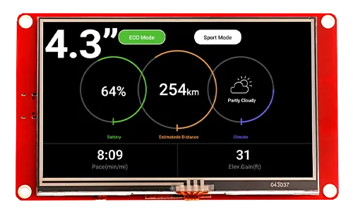
CrowPanel ESP32 HMI 4.3-inch Display
Module: DIS06043H

Updated Record
Please click on the "UPDATED RECORD" below to check the updated details in text.

Please watch below to check the updated explanation.
Feature
- lIntegrated ESP32-S3-WROOM-1-N4R2 module,built-in wireless communication 2.4 GHz Wi-Fi (802.11 b/g/n) and Bluetooth 5.0;
- Support development environment Arduino IDE, Espressif IDF, Lua RTOS, Micro python and compatible with LVGL graphics library;
- Built-in LVGL demo interface and Arduino example, plug and play;
- LCD 480*272 4.3 inches TFT-LCD with driver IC NV3047;
- Rich peripheral interfaces and expansion functions enable it to meet the needs of different fields.
Specification
- Model: 4.3 inch ESP32 display
- Main Processor: ESP32-S3-WROOM-1-N4R2
- Resolution: 480x272
- Color Depth: 16M
- Touch Type: Resistive Touch Screen
- Touch Panel: TN Panel
- Screen: TFT-LCD Screen
- Display driver: NV3047
- External power supply: DC5V-2A
- Interface: 1xTF Card Slot, 1x GPIO, 1xSpeak, 1x UART1, 1xUART0
Pin Out
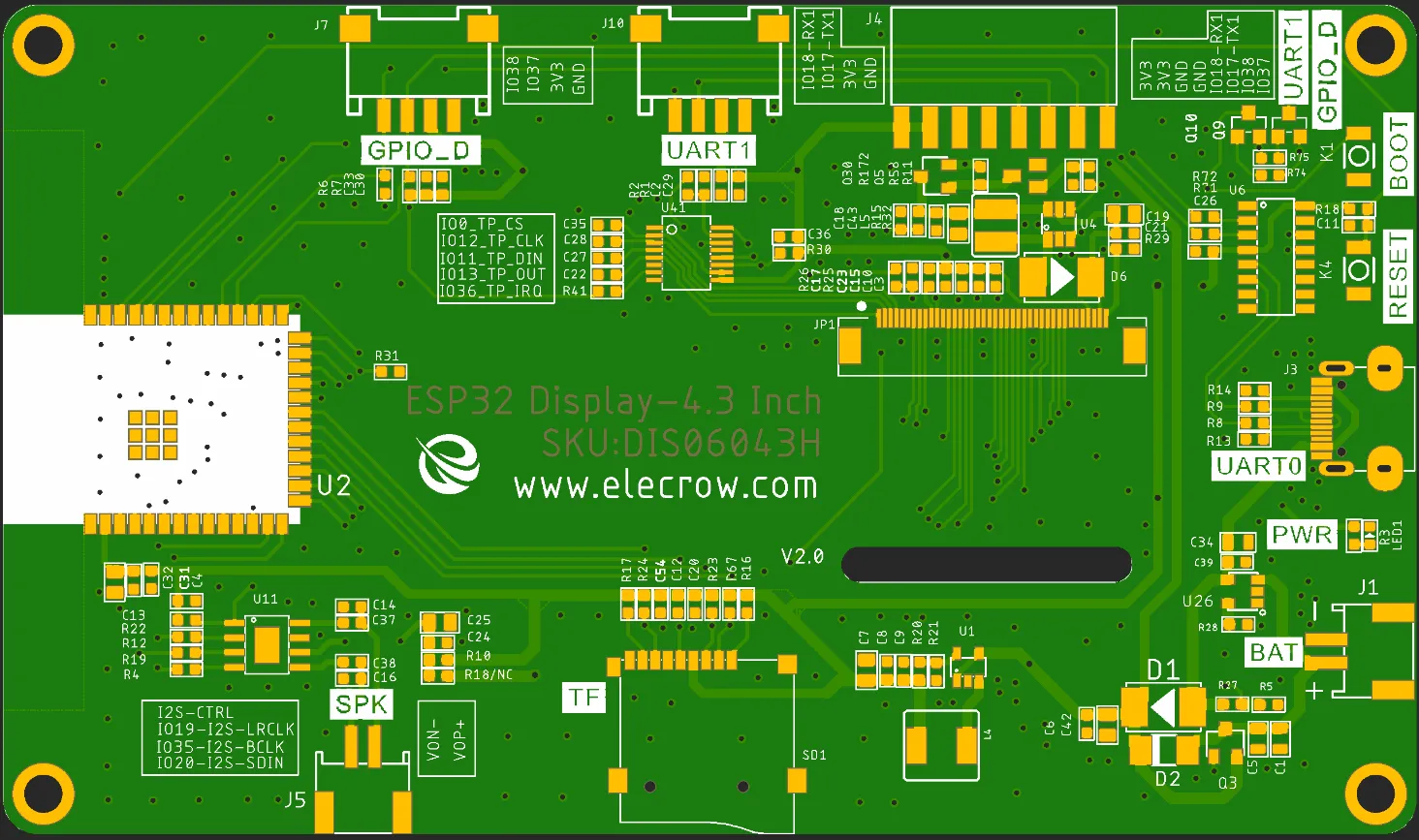
| Pin Name | Description | Connector Type |
|---|---|---|
| SPK | Output audio signal,connected with speakers. The motherboard comes with a power amplifier chip circuit. | PH2.0-2P |
| PWR | Power LED. | |
| RST | Reset button. Push it to reset the system. | |
| BOOT | ||
| GPIO_D | Digital and artificial I/O interface. | HY2.0-4P |
| TF | Provide off-line save and extra storage space. | |
| UART1 | Build the communication among Logic modules, including serial communication module and print module. | HY2.0-4P |
| BAT | Connect with the lithium battery. (With the battery charging circuit) | PH2.0-2P |
| UART0 | Provide serial communication, supply voltage(transform USB to UART0) and serial information printing. | USB-C |
| 4.3-inch HMI Port | Pin Number |
|---|---|
| GPIO_D | IO37, IO38(Can be used to simulate UART or IIC) |
| UART1 | RX(IO18); TX(IO17) |
| SPK(I2S) | I2S-CTRL(3V3); I2S-MCLK(IO19); I2S-BCLK(IO35); I2S-SDIN(IO20) |
| SD Card Slot(SPI) | MOSI(IO11); MISO(IO13); CLK(IO12); CS(IO10) |
| LCD Backlight | IO2 |
Schematic Diagram
ESP32-S3 and TFT display wiring pins
Schematic Diagram:

Definition in the main program(If use LovyanGFX library):
#define screenWidth   480
#define screenHeight  272

class LGFX : public lgfx::LGFX_Device
{
public:
    lgfx::Bus_RGB _bus_instance;
    lgfx::Panel_RGB _panel_instance;
    lgfx::Light_PWM _light_instance;
    lgfx::Touch_XPT2046 _touch_instance;
    LGFX(void)
    {
        {
            auto cfg = _panel_instance.config();
            cfg.memory_width = screenWidth;
            cfg.memory_height = screenHeight;
            cfg.panel_width = screenWidth;
            cfg.panel_height = screenHeight;
            cfg.offset_x = 0;
            cfg.offset_y = 0;
            _panel_instance.config(cfg);
        }

        {
            auto cfg = _bus_instance.config();
            cfg.panel = &_panel_instance;

            cfg.pin_d0 = GPIO_NUM_8;  // B0
            cfg.pin_d1 = GPIO_NUM_3;  // B1
            cfg.pin_d2 = GPIO_NUM_46; // B2
            cfg.pin_d3 = GPIO_NUM_9;  // B3
            cfg.pin_d4 = GPIO_NUM_1;  // B4

            cfg.pin_d5 = GPIO_NUM_5;  // G0
            cfg.pin_d6 = GPIO_NUM_6;  // G1
            cfg.pin_d7 = GPIO_NUM_7;  // G2
            cfg.pin_d8 = GPIO_NUM_15; // G3
            cfg.pin_d9 = GPIO_NUM_16; // G4
            cfg.pin_d10 = GPIO_NUM_4; // G5

            cfg.pin_d11 = GPIO_NUM_45; // R0
            cfg.pin_d12 = GPIO_NUM_48; // R1
            cfg.pin_d13 = GPIO_NUM_47; // R2
            cfg.pin_d14 = GPIO_NUM_21; // R3
            cfg.pin_d15 = GPIO_NUM_14; // R4

            cfg.pin_henable = GPIO_NUM_40;
            cfg.pin_vsync = GPIO_NUM_41;
            cfg.pin_hsync = GPIO_NUM_39;
            cfg.pin_pclk = GPIO_NUM_42;
            cfg.freq_write = 8000000;

            cfg.hsync_polarity    = 0;
            cfg.hsync_front_porch = 8;
            cfg.hsync_pulse_width = 4;
            cfg.hsync_back_porch  = 43;

            cfg.vsync_polarity    = 0;
            cfg.vsync_front_porch = 8;
            cfg.vsync_pulse_width = 4;
            cfg.vsync_back_porch  = 12;

            cfg.pclk_active_neg = 1;
            cfg.de_idle_high = 0;
            cfg.pclk_idle_high = 0;

            _bus_instance.config(cfg);
            _panel_instance.setBus(&_bus_instance);
        }

        {
            auto cfg = _light_instance.config();
            cfg.pin_bl = GPIO_NUM_2;
            _light_instance.config(cfg);
            _panel_instance.light(&_light_instance);
        }

        {
            auto touch_cfg = _touch_instance.config();
            touch_cfg.x_min      = 100;    // タッチスクリーンから得られる最小のX値(生の値)
            touch_cfg.x_max      = 4000;  // タッチスクリーンから得られる最大のX値(生の値)
            touch_cfg.y_min      = 100;    // タッチスクリーンから得られる最小のY値(生の値)
            touch_cfg.y_max      = 4000;  // タッチスクリーンから得られる最大のY値(生の値)
            touch_cfg.pin_int    = 36;   // INTが接続されているピン番号
            touch_cfg.bus_shared = true; // 画面と共通のバスを使用している場合 trueを設定
            touch_cfg.offset_rotation = 0;// 表示とタッチの向きのが一致しない場合の調整 0~7の値で設定

            // SPI接続の場合
            touch_cfg.spi_host   = SPI2_HOST; //HSPI_HOST;// 使用するSPIを選択 (HSPI_HOST or VSPI_HOST)
            touch_cfg.freq       = 1000000;     // SPIクロックを設定
            touch_cfg.pin_sclk   = GPIO_NUM_12;     // SCLKが接続されているピン番号
            touch_cfg.pin_mosi   = GPIO_NUM_11;     // MOSIが接続されているピン番号
            touch_cfg.pin_miso   = GPIO_NUM_13;     // MISOが接続されているピン番号
            touch_cfg.pin_cs     = GPIO_NUM_0;     //   CSが接続されているピン番号

            _touch_instance.config(touch_cfg);
            _panel_instance.setTouch(&_touch_instance);  // タッチスクリーンをパネルにセットします。
        }
        setPanel(&_panel_instance);
    }
};
Definition in the main program(If use Arduino_GFX library):
Arduino_ESP32RGBPanel *bus = new Arduino_ESP32RGBPanel(
  GFX_NOT_DEFINED /* CS */, GFX_NOT_DEFINED /* SCK */, GFX_NOT_DEFINED /* SDA */,
  40 /* DE */, 41 /* VSYNC */, 39 /* HSYNC */, 42 /* PCLK */,
  45 /* R0 */, 48 /* R1 */, 47 /* R2 */, 21 /* R3 */, 14 /* R4 */,
  5 /* G0 */, 6 /* G1 */, 7 /* G2 */, 15 /* G3 */, 16 /* G4 */, 4 /* G5 */,
  8 /* B0 */, 3 /* B1 */, 46 /* B2 */, 9 /* B3 */, 1 /* B4 */
);

Arduino_RPi_DPI_RGBPanel *lcd = new Arduino_RPi_DPI_RGBPanel(
  bus,
  480 /* width */, 0 /* hsync_polarity */, 8 /* hsync_front_porch */, 4 /* hsync_pulse_width */, 43 /* hsync_back_porch */,
  272 /* height */, 0 /* vsync_polarity */, 8 /* vsync_front_porch */, 4 /* vsync_pulse_width */, 12 /* vsync_back_porch */,
  1 /* pclk_active_neg */, 7000000 /* prefer_speed */, true /* auto_flush */);
ESP32-S3 and touch driver wiring
Schematic Diagram:
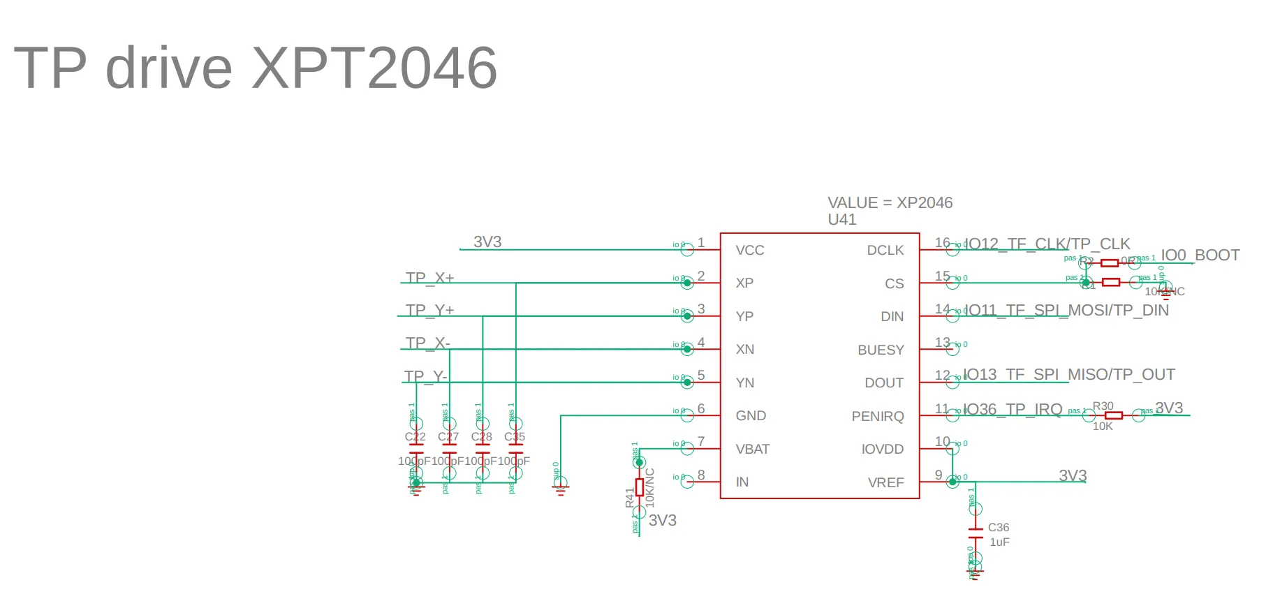
Pin definition in the touch.h:
#define TOUCH_XPT2046
#define TOUCH_XPT2046_SCK 12
#define TOUCH_XPT2046_MISO 13
#define TOUCH_XPT2046_MOSI 11
#define TOUCH_XPT2046_CS 0
#define TOUCH_XPT2046_INT 36
Platforms Supported
| Arduino IDE | SquareLine Studio | PlatformIO | Home Assistant |
|---|---|---|---|
 | |||
 | | | |
| ESPHome | MicroPython | ESP-IDF |
|---|---|---|
| | |


FAQ
- Click here to see the frequently asked questions of ESP32 display.
- Please list your question at the forum or contact techsupport@elecrow.com for technology support.
Resources
Github Link
Schematic & PCB
Specifications
Certification
- CrowPanel CE Certificate
- ESP32-S3-WROOM-1 Wi-Fi Certification
- ESP32-S3-WROOM-1 NCC Certification
- ESP32-S3-WROOM-1 IC Certification.pdf
- ESP32-S3-WROOM-1 MIC Certification.pdf