Pico Shield
Description
Raspberry Pi Pico is a new popular low-cost, high-performance microcontroller board. This Pico board can be well integrated with Crowtail sensors. Without jumpers and breadboards, you can quickly build prototypes and projects, and explore the endless possibilities of Pico.
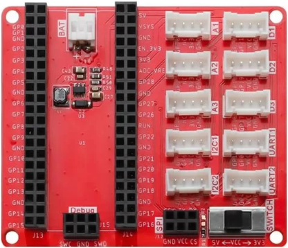
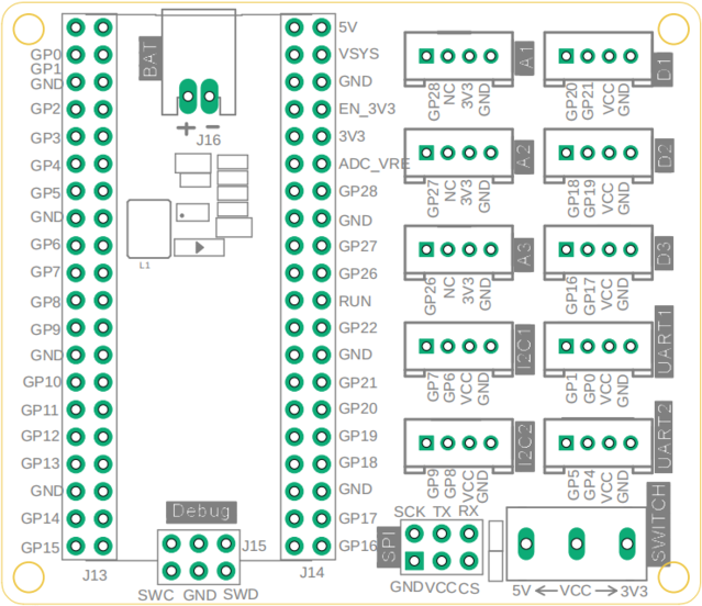
Crowtail Shield for Pi Pico is a plug-and-play expansion board for Raspberry Pi Pico, integrating various Crowtail connectors, including 2*I2C, 3*Analog, 2*UART, 3*Digital ports, 1*BAT, SWD debug interface and SPI pin, 3.3v/5v selectable power switch. The shield board is a stackable add-on board. You can directly use the Pre-Soldered Pico and plug it into the shield board, connect the Crowtail series sensors, and start developing your new project. Learn more about the Crowtail series, click here. Get the Pico board together, click here.
Model: Pico Shield
Features
- Analog Port: Include 3 analogs ports, A1, A2, A3
- Digital Port: Include 3 digital ports, D1, D2, D3
- UART Port: Include 2 UART port
- I2C Port: Include 2 I2C ports
- SPI Port: Provide one SPI port
- BAT Port: Provide one BAT port
- Power Switch: Provide 5V/3.3V selectable power switch
- Platform support: MicroPython & Arduino
- Operating Temperature: -25℃ to +85℃
- Operating voltage: Input power ⅗ V
- Dimension: 65mm * 56mm
- Weight: 26g
Interface Function
Usage
Burn Firmware
1. Use a MicroUSB cable to connect the USB interface of the Pico motherboard and the USB interface of the PC. If the Pico has not been burned into the firmware, a U disk will be generated (named: RPI-RP2);

2. Enter the official website and follow the instructions to download and burn the firmware: https://www.raspberrypi.com/documentation/microcontrollers/micropython.html
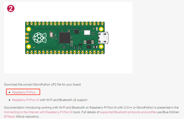
3. Operation instructions: Press and hold the BOOTSEL button, insert the USB cable connected to the Pico into the USB port of the computer, a new U disk folder will pop up on the computer, drag and drop the “UF2” file just downloaded to the folder, the Raspberry Pi Pico will restart automatically. In this way, the firmware burning is completed.
2. If there is no USB flash drive, it may be that the firmware supporting MicroPython has been burned in. At this time, we can also delete the firmware and re-import the latest version.
Software Download and Installation
1. Enter Thonny's official website: https://thonny.org/.
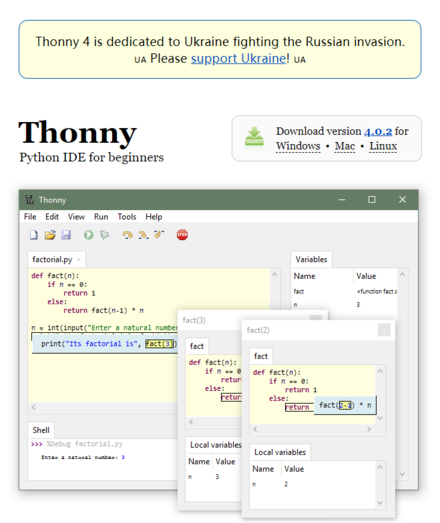
2. As shown in the figure, click to jump to the download interface, select and download the corresponding system version installation package.

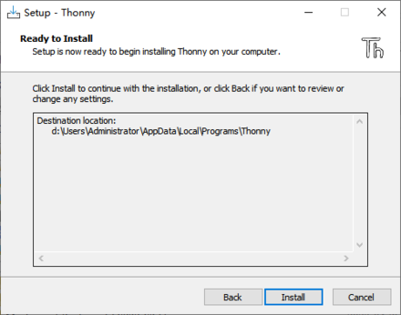
3. Open the installation package, select the installation path, and install Thonny software.
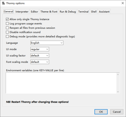
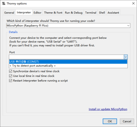
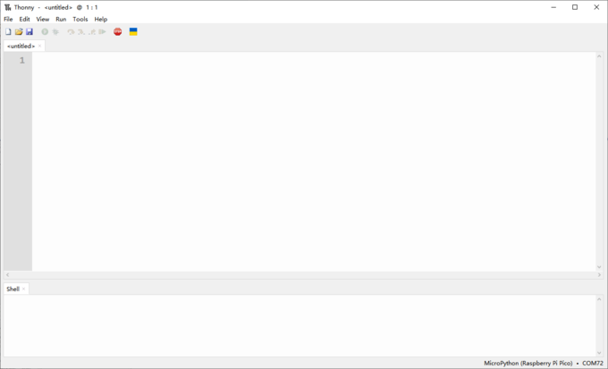
4. After opening Thonny, click "Tools" -> "Options" to open the setting window; then click "Interpreter", select "Micropython (Raspberry Pi Pico)" for the interpreter, and select the corresponding port for the port.
Program Example
Example 1: Flashing Light
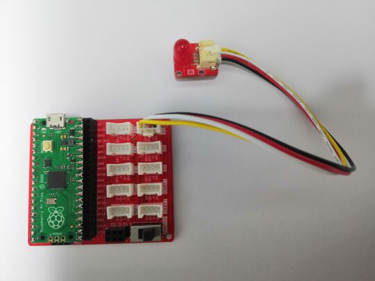
Connect the LED to the D1 port.
from machine import Pin
import time
led = Pin(20, Pin.OUT)
if __name__ == '__main__':
    while True:
        led.value(1)
        time.sleep(0.1)
        led.value(0)
        time.sleep(0.1)
cleanup()
Example 2: Switch Light
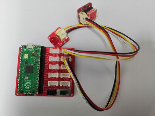
Connect the LED and the button to D1 port and D2 port respectively.
from machine import Pin
from  utime  import sleep_ms
button = Pin(18, Pin.IN, Pin.PULL_UP)
led = Pin(20, Pin.OUT)
State=0
if __name__ == '__main__':
    while True:
        print(button.value())
        if button.value() == 0:
            if State==0:
                led.value(1)
                sleep_ms(100)
                while button.value() == 0:
                   State = 1
            else:
                led.value(0)
                sleep_ms(100)
                while button.value()== 0:
                    State = 0
Example 3: Ultrasonic Ranging
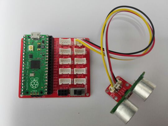
Connect the ultrasonic ranging sensor to the D1 port.
from machine import Pin
import utime
trigger = Pin(20, Pin.OUT)
echo = Pin(21, Pin.IN)
def getDistance(trigger, echo):
    trigger.low()
    utime.sleep_us(2)
    trigger.high()
    utime.sleep_us(10)
    trigger.low()
    while echo.value() == 0:
        start = utime.ticks_us()
    while echo.value() == 1:
        end = utime.ticks_us()
    d = (end - start) * 0.0343 / 2
    return d
if __name__ == '__main__':
    while True:
        distance = getDistance(trigger, echo)
        print("distance:{:.2f} cm".format(distance))
        utime.sleep(0.1)
Example 4: Dimmer
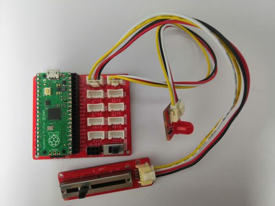
Connect the LED and the rotary angle sensor to D1 port and A1 port respectively.
from machine import Pin,ADC,PWM
from time import sleep
Led_pin = 20
Potentiometer_pin = 2
def setup():
    global LED
    global Pot_ADC
    LED = PWM(Pin(Led_pin))
    LED.freq(2000)
    Pot_ADC = ADC(Potentiometer_pin)
def loop():
    while True:
        print ('Potentiometer Value:', Pot_ADC.read_u16())
        Value = Pot_ADC.read_u16()
        LED.duty_u16(Value)
        sleep(0.2)
if __name__ == '__main__':
    setup()
    loop()
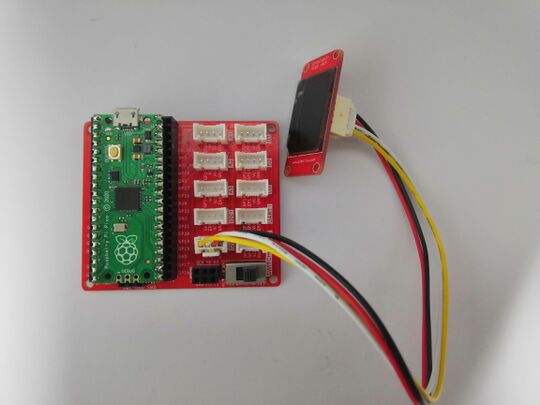
Example 5: OLED Display
- Connect the OLED to the I2C2 port;
- Upload the "ssd1306.py" file to the Raspberry Pi Pico.
from machine import Pin, I2C
from ssd1306 import SSD1306_I2C
import time
list = [2022, 7, 4, 14, 42, 25]
mon_max = [1,3,5,7,8,10,12]
mon_min = [4,6,9,11]
i2c=I2C(0,sda=Pin(8), scl=Pin(9), freq=400000)
oled = SSD1306_I2C(128, 64, i2c)
def set_time():
    global text1
    if list[5] > 9:
        if list[4] > 9:
            text1 = 'Time:%d:%d:%d'%(list[3],list[4],list[5])
        else:
            text1 = 'Time:%d:0%d:%d'%(list[3],list[4],list[5])
    else:
        if list[4] > 9:
            text1 = 'Time:%d:%d:0%d'%(list[3],list[4],list[5])
        else:
            text1 = 'Time:%d:0%d:0%d'%(list[3],list[4],list[5])
def set_date():
    global text2
    if list[2] > 9:
        if list[1] > 9:
            text2 = 'Date:%d.%d.%d'%(list[0],list[1],list[2])
        else:
            text2 = 'Date:%d.0%d.%d'%(list[0],list[1],list[2])
    else:
        if list[1] > 9:
            text2 = 'Date:%d.%d.0%d'%(list[0],list[1],list[2])
        else:
            text2 = 'Date:%d.0%d.0%d'%(list[0],list[1],list[2])
def date_change():
    list[2] = 1
    list[1] += 1
    if list[1] > 12:
        list[1] = 1
        list[0] += 1
def time_change():
    list[5] += 1
    if list[5] > 59:
        list[5] = 0
        list[4] += 1
        if list[4] > 59:
            list[4] = 0
            list[3] += 1
            if list[3] > 23:
                list[3] = 0
                list[2] += 1
                if list[1] in mon_max:
                    if list[2] > 31:
                        date_change()
                elif list[1] in mon_min:
                    if list[2] > 30:
                        date_change()
                elif list[1] == 2:
                    if (list[0] % 4 == 0 and list[0] % 100 != 0) or list[0] % 400 == 0:
                        if list[2] > 29:
                            date_change()
                        elif list[2] > 28:
                            date_change()
if __name__ == '__main__':
    while True:
        set_date()
        oled.text(text2, 0, 0)
        set_time()
        oled.text(text1, 8, 12)
        oled.show()
        time_change()
        time.sleep(1)
        oled.fill(0)
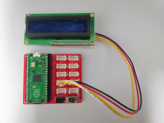
Example 6: LCD Display
- Connect the I2C LCD to the I2C1 port;
- Upload the lcd_api.py and pico_i2c_adafruit_lcd.py file to the Raspberry Pi Pico.
from machine import I2C, Pin
import utime
from pico_i2c_adafruit_lcd import I2cLcd
DEFAULT_I2C_ADDR = 0x20
BUS = 1
LCD_SDA = Pin(6, Pin.PULL_UP)
LCD_SCL = Pin(7, Pin.PULL_UP)
i2c = I2C(BUS, sda=LCD_SDA, scl=LCD_SCL, freq = 400000)
lcd = I2cLcd(i2c, DEFAULT_I2C_ADDR, 2, 16)
lcd.putstr("Elecrow 2013")
utime.sleep_ms(3000)
lcd.clear()
count = 0
if __name__ == "__main__":
    while True:
        lcd.move_to(0, 0)
        lcd.putstr("Crowtail - Pico")
        utime.sleep_ms(1000)
        lcd.clear()
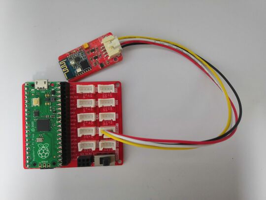
Example 7: Bluetooth Control
- Connect the BLE module to the UART1 port;
- Download a Bluetooth serial port assistant on the mobile phone, turn on the mobile phone Bluetooth, search and connect the HMSoft device, and send characters.
import machine
import utime
uart = machine.UART(0, baudrate=115200, tx=machine.Pin(0), rx=machine.Pin(1))
print(uart)
led = machine.Pin(25, machine.Pin.OUT)
if __name__ == '__main__':
    while True:
        if uart.any() == True:
            cmd = uart.read(1)
            print(cmd)
            if cmd == b'a':
                led.value(1)
            if cmd == b'b':
                led.value(0)
        utime.sleep(0.1)
Resources
Support
If you have any problem about how to use it, you can connect to us at the bottom-right of bazzer or contact to techsupport@elecrow.com to get technology support.
