Lesson01---Print "Hello World"
Introduction
In this class, we will officially learn to write code in the ESP-IDF environment to drive the Advance-P4 development board. The subsequent courses will follow a gradient design from simple to complex, helping you gradually master the ESP-IDF development framework and the usage logic of the ESP32-P4 chip, and establish a clear technical understanding. Specifically for this class, there are two core goals: First, to teach you how to create and burn a basic program in ESP-IDF, achieving the first "communication" between your computer and the ESP32-P4 chip on the Advance-P4 development board; second, to enable you to clearly see the "Hello World" information printed in real-time by the chip in the terminal window of the ESP-IDF tool, completing the crucial step from "configuring the environment" to "verifying the function".
Hardware Used in This Lesson
This class does not involve the use of hardware. It is only to teach you how to create a new project and how to flash code to the ESP32-P4 chip on ESP-IDF.
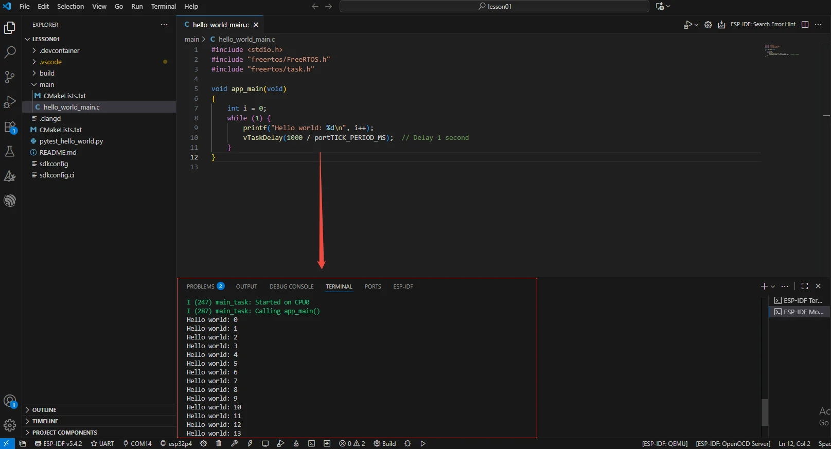
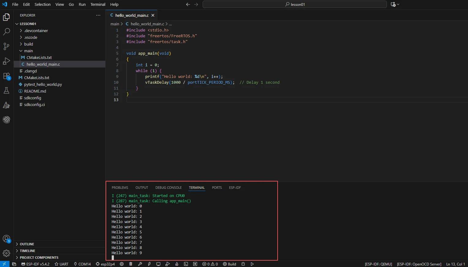
Operation Effect Diagram
When running on the ESP32-P4, the serial terminal will output "Hello world" with an increasing counter every 1 second.
Key Explanations
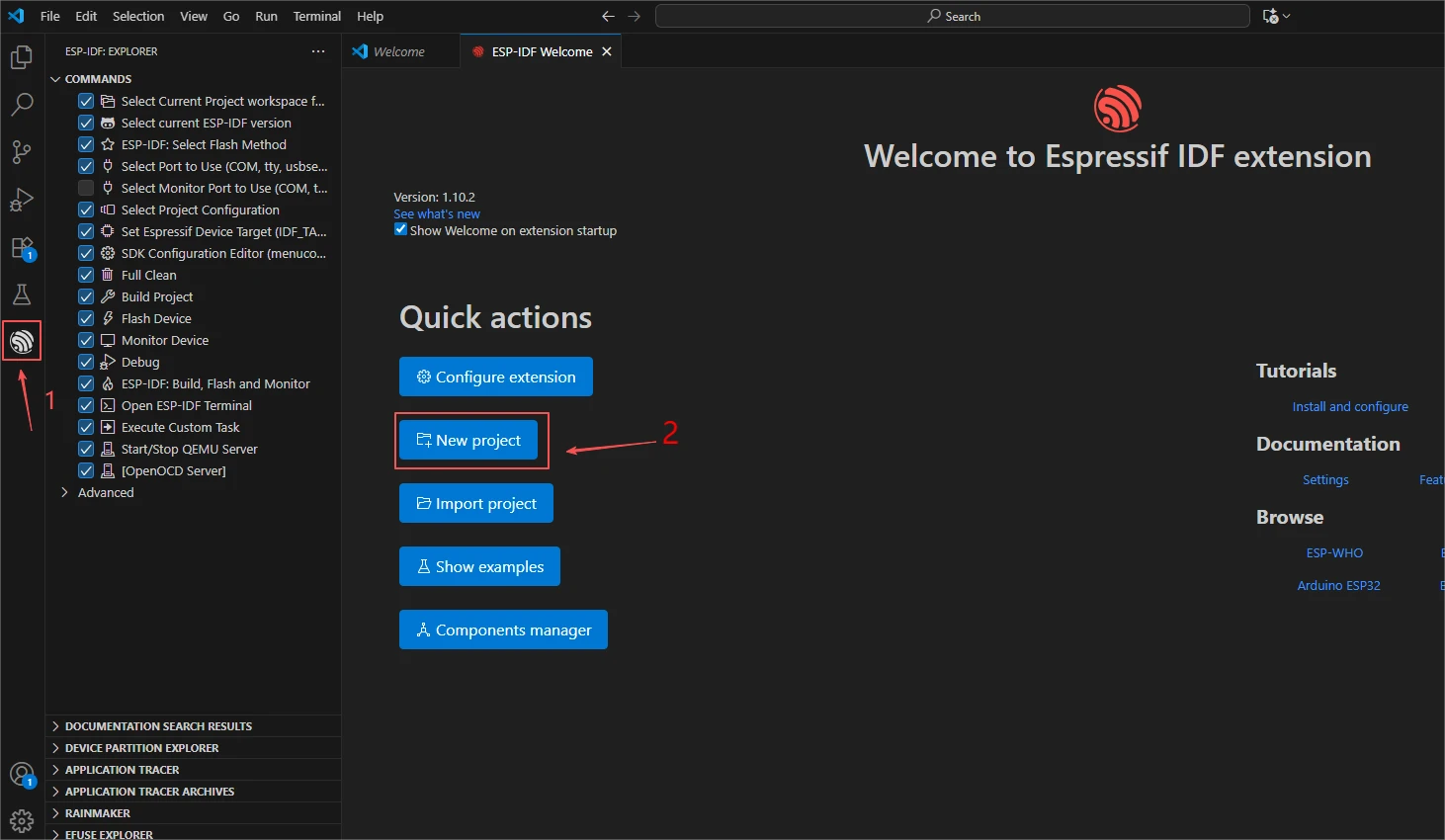
First, let's talk about how to create a new project in the already installed ESP-IDF.
Click on the ESP-IDF icon, then click "New project"
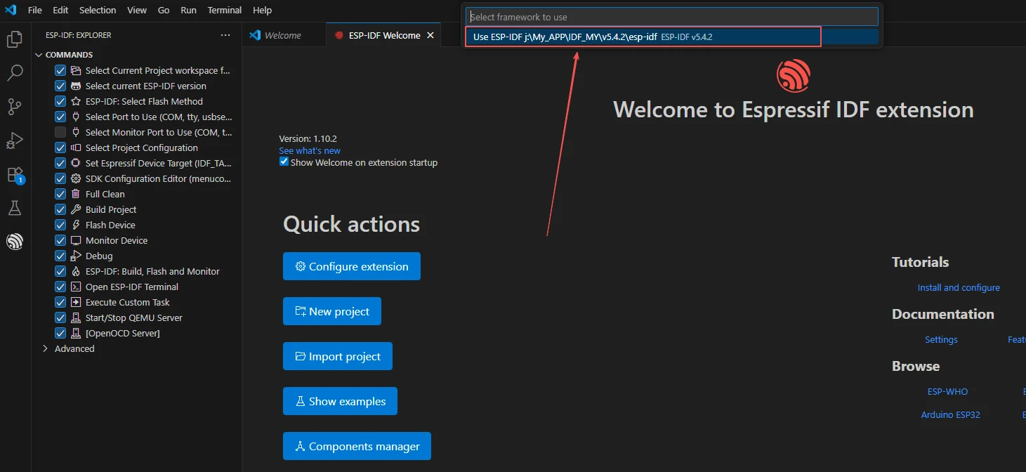
Then a version of the ESP-IDF environment that you configured in the previous class will pop up.
Select the 5.4.2 version that you previously set up.
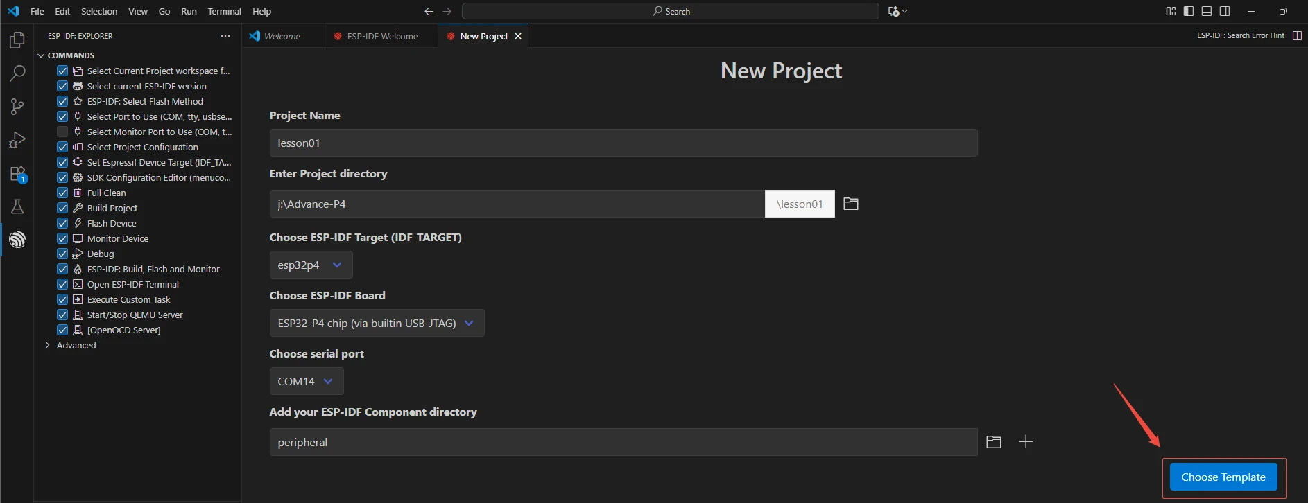
Then, enter this configuration interface. Here, fill in and set the name, path, target chip, serial port, and the folder name for the subsequent used component files of your newly created project.
Finally, select the template.
Choose ESP-IDF
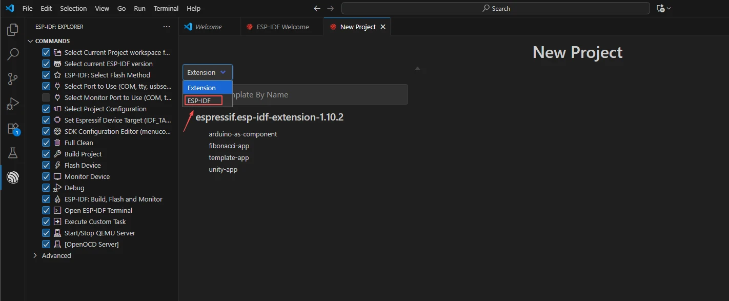
After selecting "Hello World", click "Confirm Creation" (you can also take a detailed look at the official introduction of this interface).
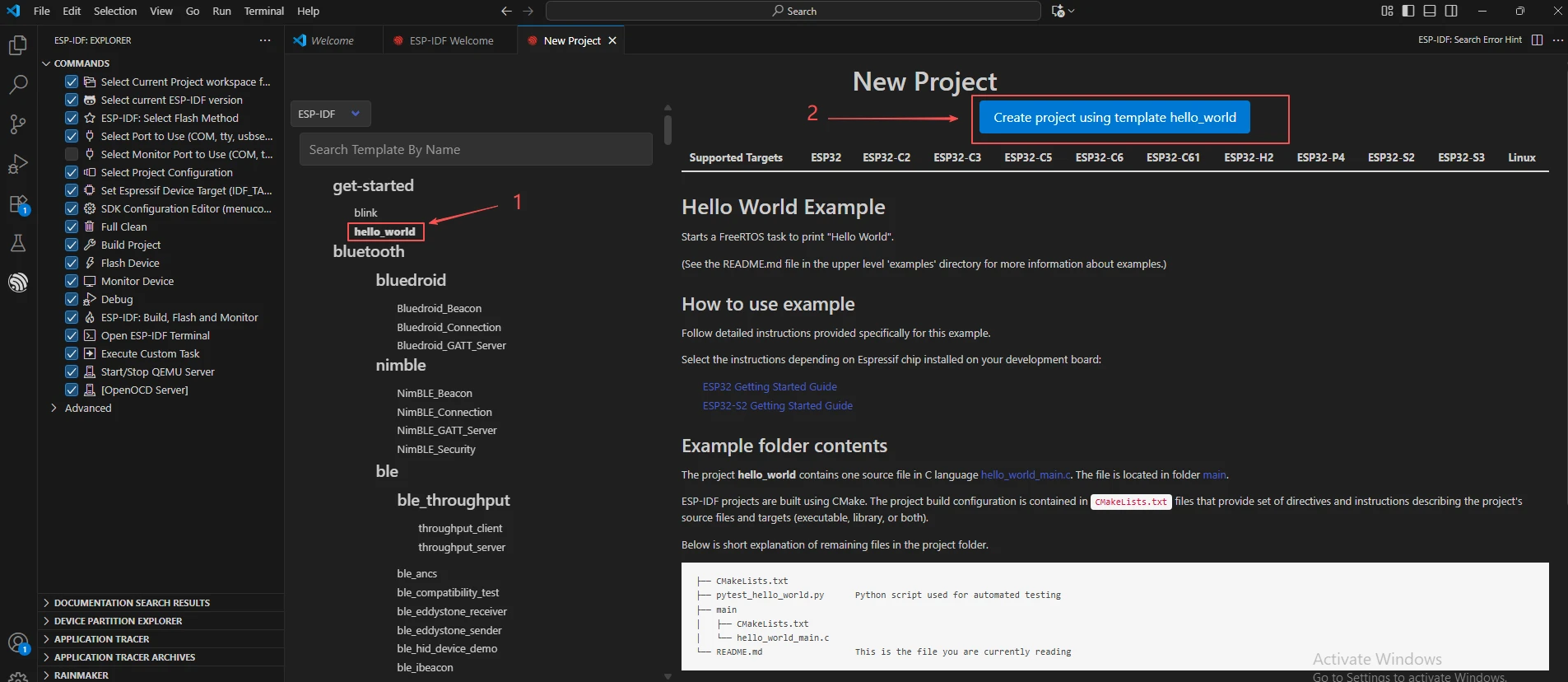
Thus, we have successfully created the new project.
Subsequently, we will modify the code based on this project and add the necessary components we need to use in the subsequent courses.
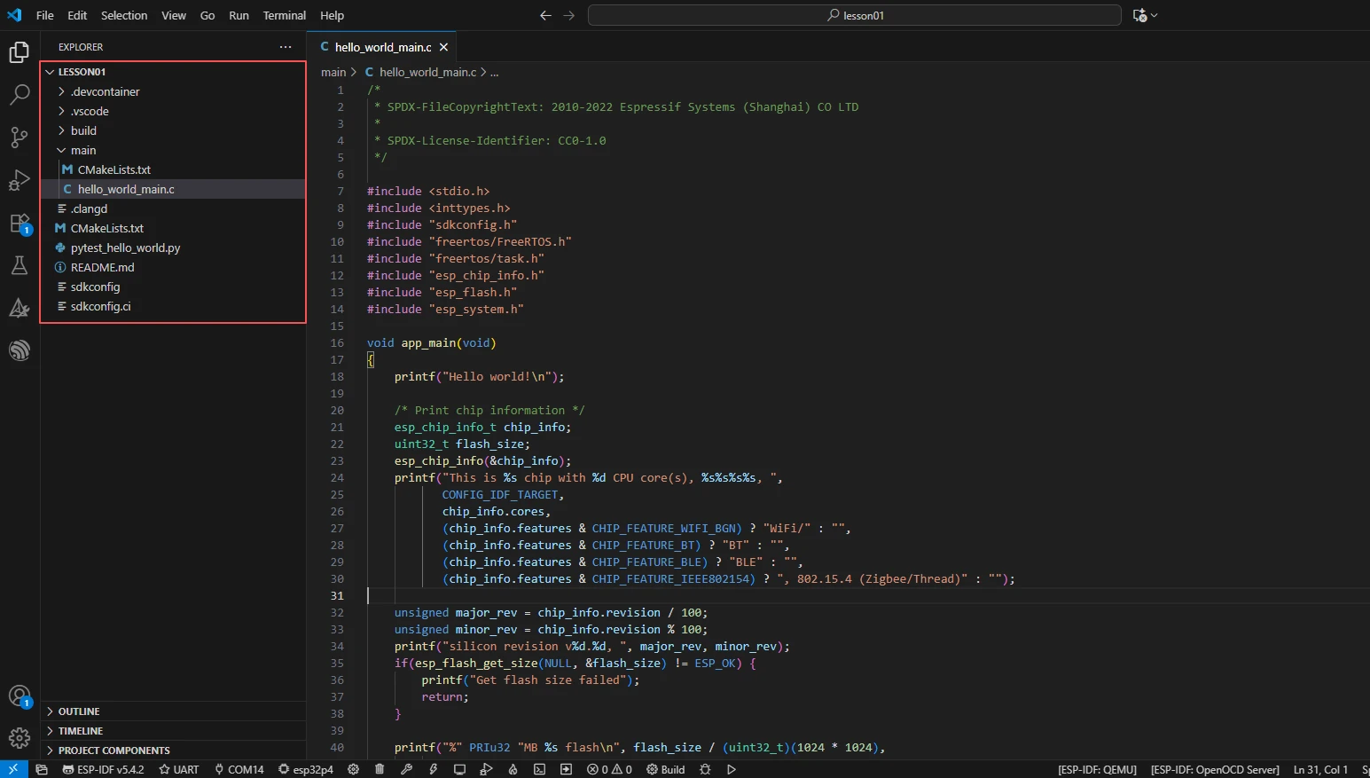
Now, we can modify the hello_world_main.c function.
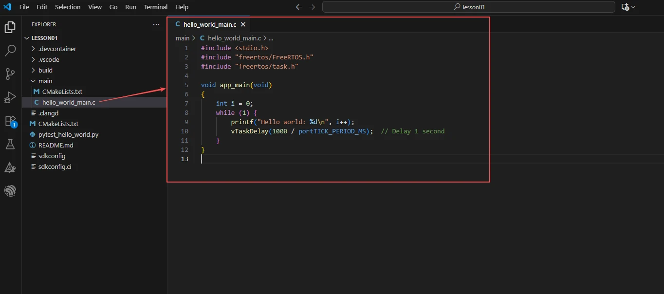
Since in this class, I want to achieve the loop printing of "hello world:i" and continuously increment i, I deleted this sample code and replaced it with the code I wrote myself.
Next, we will provide a detailed explanation of this code to help everyone have a clear understanding.
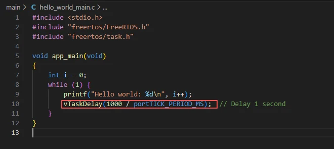
When this code runs on the ESP32-P4, it outputs "Hello world" with an increasing counter every 1 second through the serial port. It utilizes the delay mechanism of FreeRTOS to achieve a non-blocking loop.
The program first imports stdio.h to use 'printf()' for outputting debugging information. Then, it includes FreeRTOS.h and task.h, allowing the use of task management and delay functions provided by FreeRTOS. Based on this, the main function uses 'printf()' to print the content and controls the loop rhythm using 'vTaskDelay()' to achieve outputting information every 1 second without blocking the operation of other system tasks.

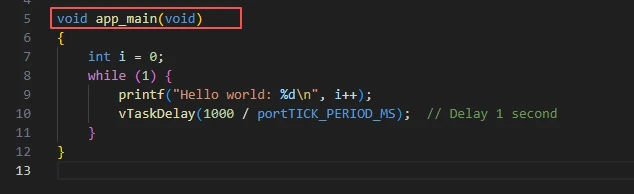
In ESP-IDF, the entry function of the program is not main(), but app_main().
This function will be automatically called by the IDF framework.
Note: app_main is actually a FreeRTOS task (the main task), so you can write an infinite loop in it.
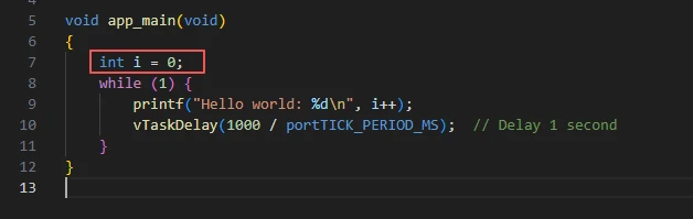
i is a counter, with an initial value of 0.
It increments after each loop.
printf("Hello world: %d\n", i++);
Output "Hello world: i" to the serial port.
i++: First use the value of i, then increment i by 1.

vTaskDelay(1000 / portTICK_PERIOD_MS): This function delays the current task for a certain period of time.
Parameter explanation:
1000: The duration of the delay (in milliseconds).
portTICK_PERIOD_MS: The number of milliseconds corresponding to one tick in the system.
For example, if FreeRTOS is configured such that 1 tick = 1 ms, then 1000 / 1 = 1000 ticks = 1 second.
Therefore, vTaskDelay(1000 / portTICK_PERIOD_MS); is equivalent to delaying for 1 second.
Complete Code
Kindly click the link below to view the full code implementation.
GitHub Link
Programming Steps
Now the code is ready. Next, we need to flash the ESP32-P4 so that we can observe the results.
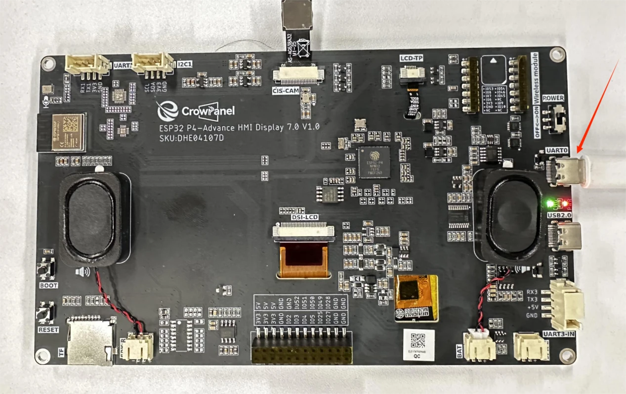
First, we connect the Advance-P4 device to our computer host via the USB cable. (Connect UART0)
In order of priority, select the ESP-IDF version 5.4.2 that you are currently using.
We are using serial flash programming, so select UART.
Since the serial port number displayed may vary depending on your device, after clicking 3, select the serial port that belongs to your own device.
Make sure that you are using the esp32-p4 chip.
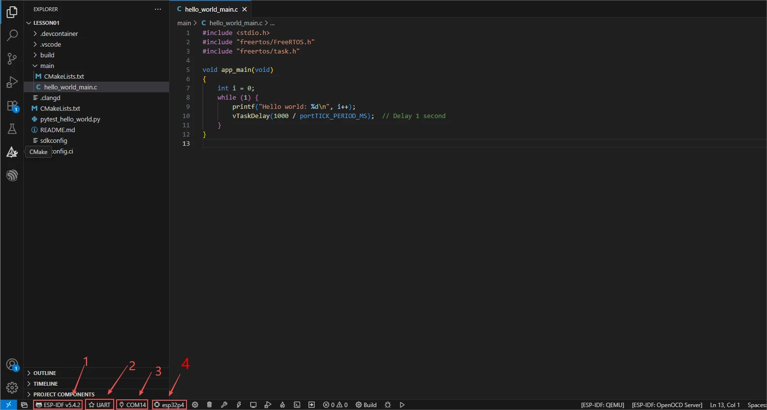
After configuring 1, 2, 3, and 4 as mentioned above, we will proceed to compile the project to check if there are any issues with the code.
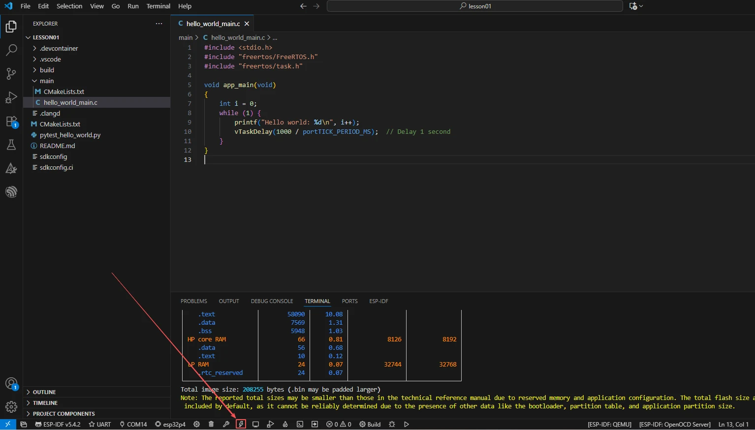
First, click on 1 in the picture below, which represents the function of compiling the code.
Wait for a while, after the code is compiled, you will be able to see the following information in the terminal, indicating that your code has been compiled successfully.

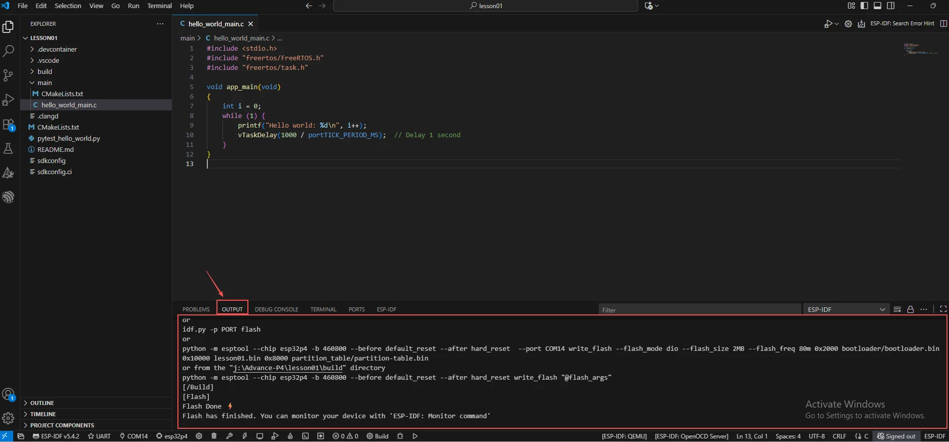
Then, click the "Burn" button.
After waiting for a while, you will be able to see from the displayed information on the output that the code has been uploaded successfully.
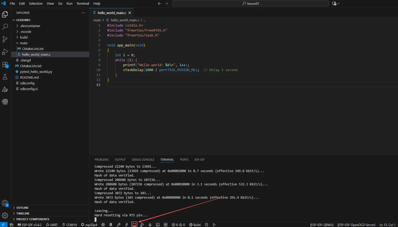
Of course, you can also see from the upload process displayed on the terminal that your code has been uploaded successfully.

Next, all you need to do is to open the serial port monitor, and then you will be able to see that "hello world" is being printed.
So, that's all for this lesson. In the next class, we will gradually increase the difficulty level. We will teach you how to use components, how components are related to the main function, and how to have the main function utilize the interfaces within the components.