Lesson02---Turn on the LED
Introduction
In this class, we will start to explore the most important component in ESP-IDF.
In this class, we will use the bsp_extra component we have written ourselves to control the level of the UART1 interface on the Advance-P4, so that the LED connected to the UART1 interface will light up for one second and then go off for one second.
Hardware Used in This Lesson
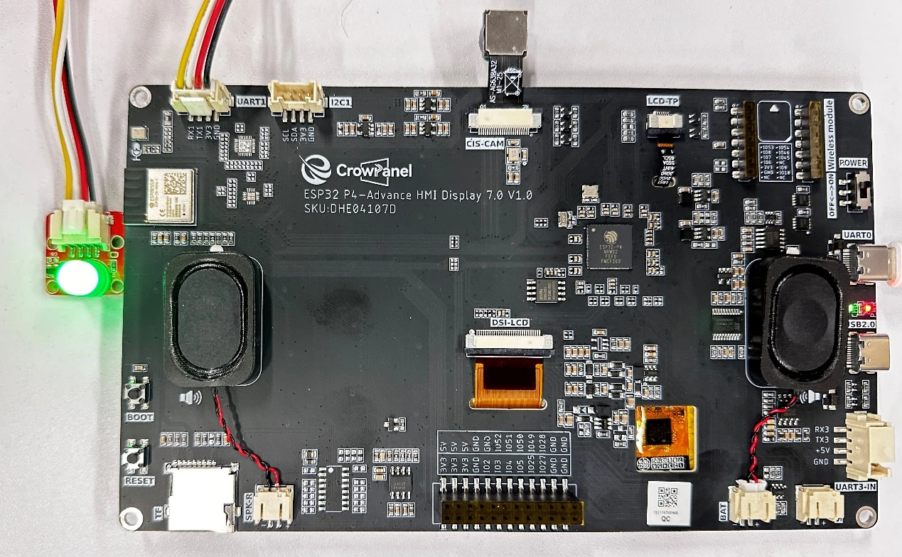
Introduction to the UART1 Interface on Advance-P4
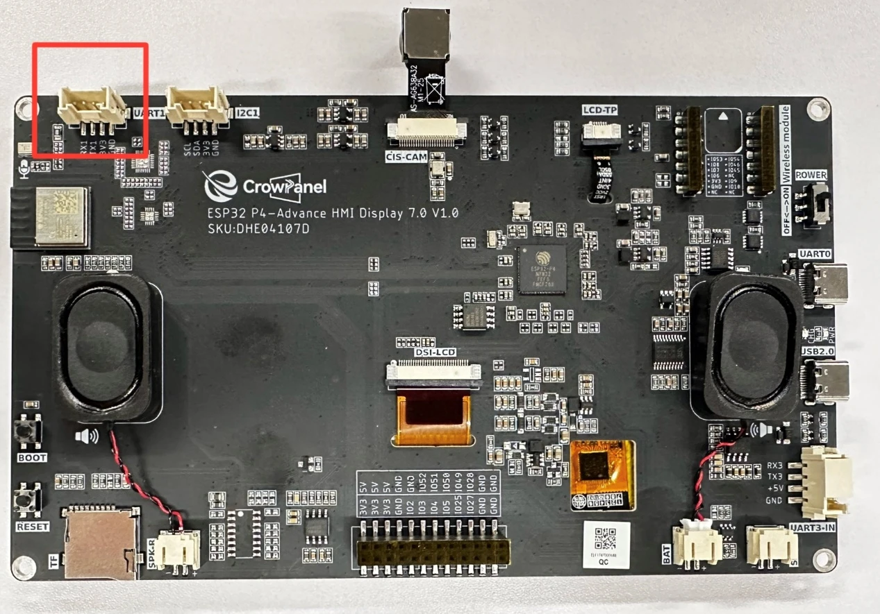
On our Advance-P4 board, the UART1 interface is identified by the name "UART". We should look for an interface that can be used for serial communication. Moreover, during the initial design phase, this UART1 interface can also be used as a regular GPIO port. That is, we can treat the RX and TX pins on this interface as two regular GPIO ports.
Introduction to GPIO
The ESP32-P4 chip offers 55 general-purpose input/output (GPIO) functions, providing flexibility and adaptability for a wide range of applications. The key features of these GPIOs include:
① Multi-functionality: Each GPIO pin can not only be used as an input or output, but can also be configured as various roles through IO MUX (refer to Chapter 2 for details), such as PWM, ADC, I2C, SPI, etc. This enables the ESP32-P4 to adapt to various peripheral connections.
② High current output: The GPIO pins of ESP32-P4 support up to 40mA of current output, allowing direct driving of low-power loads such as LEDs. This reduces the complexity of external driver circuits.
③ Programmability: Through the ESP-IDF (SDK) development framework, users can flexibly configure the input/output mode, pull-up/pull-down parameters, and other settings of each GPIO to meet specific application requirements.
④ Interrupt support: GPIO pins support interrupt functionality, which can trigger interrupts when the signal changes. This is suitable for real-time response applications such as button detection and sensor triggering.
⑤ Status indication: GPIO pins can be used as LED indicators, achieving status visualization through simple high/low level switching. This helps users debug and monitor system operation.
The GPIO functions of ESP32-P4 provide powerful hardware support for developers. In this chapter, we will delve into the application and configuration of GPIO through an example of lighting an LED.
Introduction to LED
LED is a highly efficient and durable miniature semiconductor device that emits light when an electric current passes through it. It has the advantages of high energy conversion efficiency, low heat generation, and environmental friendliness. They are commonly used in indicator lights, display screens, and lighting equipment. LEDs have fast response times and a wide range of color options, making them widely used in electronic products. In the ESP32-P4 lighting demonstration, GPIO control simplifies and makes it intuitive to switch the LEDs, helping users better understand their practical applications.
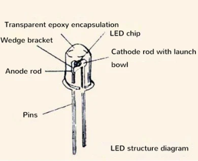
① The principle of LED light emission
LED devices are light-emitting components based on solid-state semiconductor technology. When a forward current is applied to a semiconductor material with a PN junction, the recombination of charge carriers within the semiconductor releases energy in the form of photons, thereby generating light. Therefore, LEDs are cold light sources, unlike lighting based on filament, which generates heat and thus avoids problems such as burning out. The following chart illustrates the operating principle of LED devices.
In the above chart, the PN junction of the semiconductor exhibits the characteristics of forward conduction, reverse blocking, and breakdown. When there is no external bias and the junction is in a thermal equilibrium state, no carrier recombination occurs within the PN junction, and thus no light emission is produced. However, when a forward bias is applied, the light emission process of the PN junction can be divided into three stages:
Firstly, carriers are injected under forward bias;
Secondly, electrons and holes recombine within the P region, releasing energy;
Finally, the energy released during the recombination process is radiated outward in the form of light. In summary, when current passes through the PN junction, electrons are driven to the P region by the electric field. There, they combine with holes, releasing excess energy and generating photons, thereby achieving the light-emitting function of the PN junction.
Note: The color of the light emitted by an LED is determined by the band gap width of the semiconductor material used. Different materials will produce light of different wavelengths, thus being able to generate light output of various colors. This efficient light-emitting mechanism has made light-emitting diodes widely adopted in lighting and indication applications.
② Principle of LED Lighting Driver
LED driving refers to providing appropriate current and voltage to LEDs through a stable power supply to ensure their normal lighting. The main driving methods for LEDs are constant current driving and constant voltage driving, among which constant current driving is more favored as it can limit the current. Due to the fact that LED lights are very sensitive to current fluctuations, exceeding their rated current may cause damage. Therefore, constant current driving ensures the operation of LEDs by maintaining a stable current flow. Next, we will study these two LED driving methods.
1) Current injection connection. This refers to the working current of the LED being provided externally, and the current is injected into our microcontroller.
The risk here is that the fluctuations of the external power supply can easily cause the microcontroller pins to burn out.

2) Power current configuration. This refers to the voltage and current provided by the microcontroller, and the current output will be applied to the LED. If the LED is driven directly by the GPIO of the microcontroller, its driving capability is relatively weak and may not be able to provide sufficient current for driving the LED.
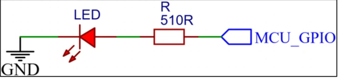
The LED circuit on the ESP32-P4 development board adopts the "current receiving" configuration. This approach avoids the microcontroller directly powering and supplying current to the LED, thereby effectively reducing the load on the microcontroller. This enables the microcontroller to focus more on performing other core tasks, thereby enhancing the performance and stability of the entire system.
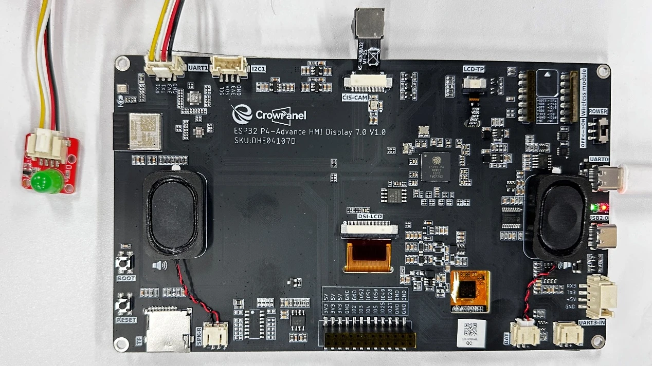
Operation Effect Diagram
After running the code, you will be able to observe that the LED connected to the UART1 interface will light up for one second and then go off for one second.
Key Explanations
Now let's talk about how the overall code framework is structured and connected after adding the bsp_extra component?
With this question in mind, let's explore it together. First, click on the Github link below and download the code for this lesson.
GitHub Link
Then, drag the code of this lesson into VS Code and open the project file.
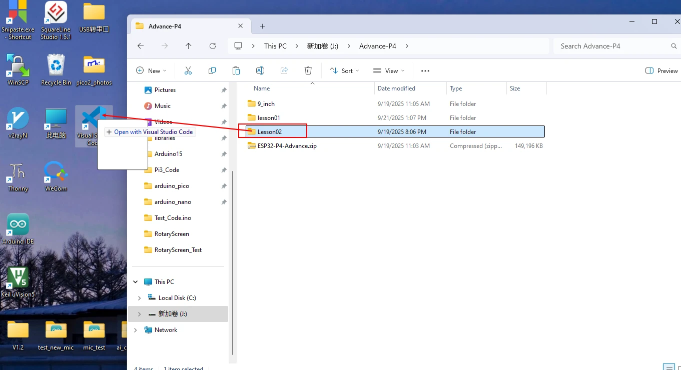
The code in the subsequent courses will also be opened in this way.
From now on, there will be no further explanation on how to open the code.
After opening it, you can see the framework of this project.
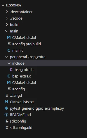
In the example of this class, a new folder named "bsp_extra" was created under "LESSON02/peripheral". Inside the "bsp_extra" folder, a new "include" folder, a "CMakeLists.txt" file, and a "Kconfig" file were created.
The "bsp_extra" folder contains the "bsp_extra.c" driver file, and the "include" folder contains the "bsp_extra.h" header file.
The "CMakeLists.txt" file integrates the driver into the build system, enabling the project to utilize the GPIO driver functionality.
The "Kconfig" file loads the entire driver and GPIO pin definitions into the sdkconfig file within the IDF platform (which can be configured through the graphical interface).
Initialization of GPIO code
The GPIO source code consists of two files: "bsp_extra.c" and "bsp_extra.h".
Next, we will first analyze the "bsp_extra.h" program: it contains the relevant definitions and function declarations for GPIO pins.
In this component, all the libraries we will use are placed in the "bsp_extra.h" file, so they can be managed uniformly.
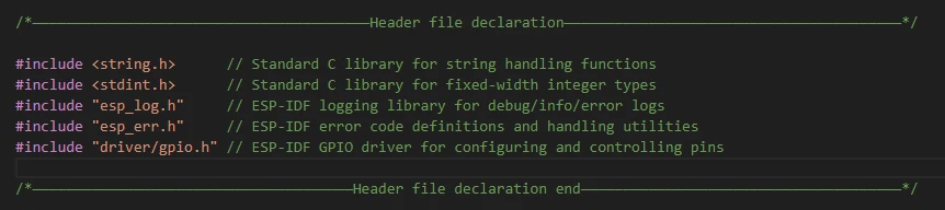
Below is the interface definition in the header file, which provides unified macros and function interfaces for the implementation file (.c).
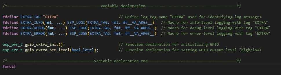
This is the content of "bsp_extra.h" (which is also what needs to be done in every .h file).
Next, we will analyze the code in the "bsp_extra.c" file: including the initialization configuration and functional code for the LED pins.
First, include the "bsp_extra.h" that we just explained, so that we can use the macros and header files declared in "bsp_extra.h".

The gpio_extra_init() function is used to configure GPIO48 of the ESP32-P4 as an output pin.

Define the return type: esp_err_t, which is the standard error code type of ESP-IDF.
Variable err: Stores the return value of the function call, initially set to ESP_OK (success).
gpio_config_t gpio_config: Prepare a configuration structure, which contains various settings for the pin.
-
.pin_bit_mask = (1ULL \<\< 48) → Select GPIO48.
-
.mode = GPIO_MODE_OUTPUT → Configure as output mode.
-
.pull_up_en / .pull_down_en = false → Do not enable the internal pull-up/pull-down resistors.
-
.intr_type = GPIO_INTR_DISABLE → Disable interrupts.
Call gpio_config() → Actually apply the configuration to the hardware.
The gpio_extra_set_level() function is used to set the level (high or low) of this pin, thereby controlling external devices such as LEDs.
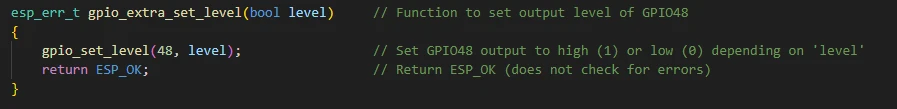
Function parameter level: Boolean value. True indicates a high level (1), and false indicates a low level (0). Call gpio_set_level(48, level): Set GPIO48 to the corresponding level.
CMkaLists.txt file
The function of this example routine mainly relies on the bsp_extra driver. To successfully call the contents within the bsp_extra folder in the main function, a CMakeLists.txt file must be created and configured within the bsp_extra folder.
The configuration details are as follows:
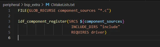
In ESP-IDF, each component directory (such as peripheral) must have a CMakeLists.txt file, which mainly performs two tasks:
- Declaration of Source File
SRCS specifies the .c files to be compiled within this component.
INCLUDE_DIRS specifies the paths of header files, allowing other components to #include.
- Define dependencies
If your peripheral module needs to use the IDF library (such as a driver), write it in the REQUIRES section, for example:
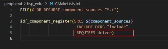
The "driver" library here is because we used the "gpio" library in the "bsp_extra.h" file.

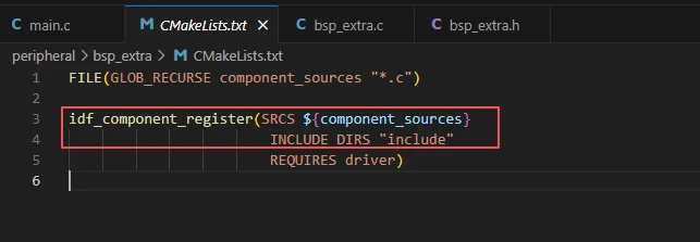
"peripheral/CMakeLists.txt" is what tells ESP-IDF: which source files and header files are included in the peripheral component, as well as which libraries it depends on.
If this file is missing, the code in the peripheral directory will not be compiled into your project.
Note: In the subsequent lessons, we will not start from scratch to create a new "CMakeLists.txt" file. Instead, we will make a few modifications to this existing file to incorporate more drivers into the build system.
main
The main folder is the core directory for program execution, and it contains the executable file main.c of the main function. Add the main folder to the CMakeLists.txt file of the build system.
This is the entry file of the entire application. In ESP-IDF, there is no int main(), but the program starts running from void app_main(void).
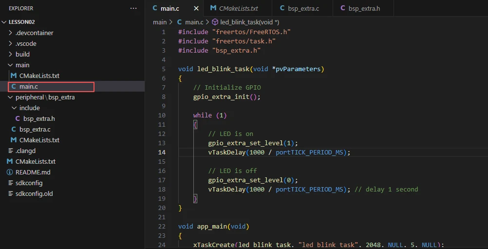
Let's first explain main.c.
Introduce the types of FreeRTOS and the task APIs (such as xTaskCreate, vTaskDelay, etc.).
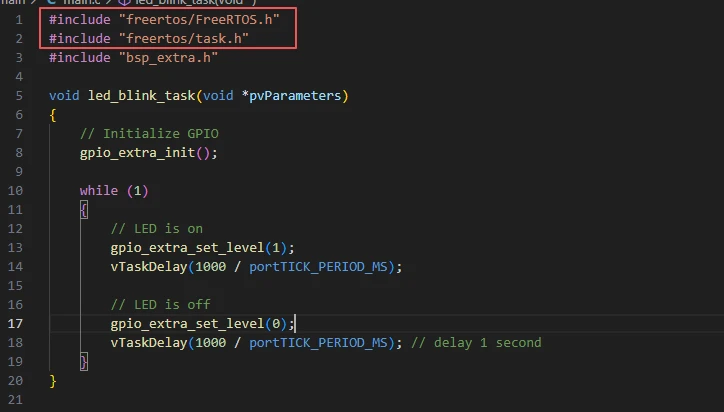
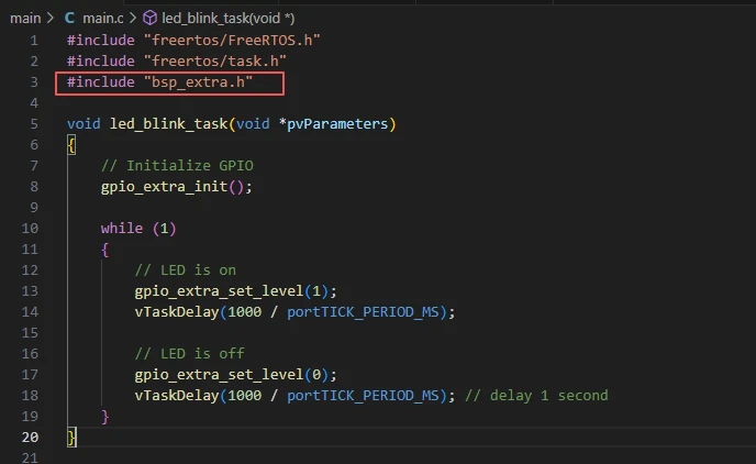
Our peripheral header files (placed in the "peripheral" component).
"bsp_extra.h" should declare interfaces such as gpio_extra_init() and gpio_extra_set_level().
Initialize GPIO (implemented in our peripheral/bsp_extra)
When explaining the "bsp_extra.c" file, it was explained that here we can directly call it for use.

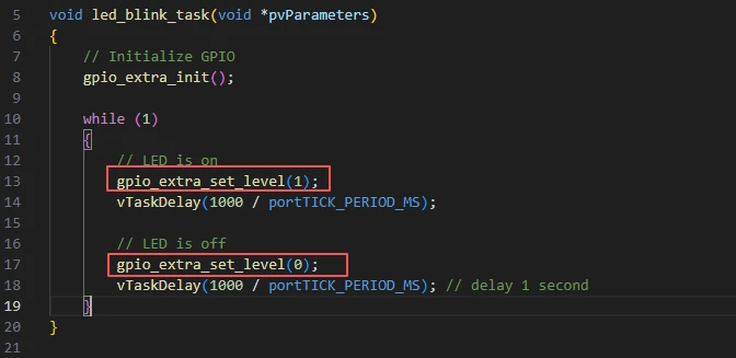
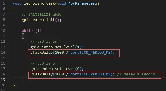
Then it enters the while loop, causing the LED light to repeatedly turn on for one second and off for one second.
Next, it calls the function for turning on or off the LED in the "bsp_extra.c" file.
Just by modifying parameter 1 or 0, it will take effect.
1: High level (on) 0: Low level (off)
Then, the delay function from the FreeRTOS library is called to delay for one second.
app_main is the program entry point of ESP-IDF (called after system startup).
In FreeRTOS, create a task named "led_blink_task", which will execute the led_blink_task function with a priority of 5 and using a 2048-byte stack to implement the LED blinking logic.
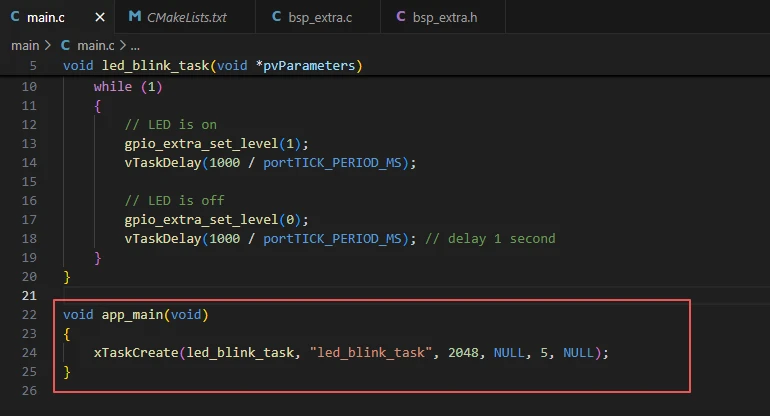
xTaskCreate(led_blink_task, "led_blink_task", 2048, NULL, 5, NULL);
Parameter meanings:
led_blink_task: Entry function of the task
"led_blink_task": Task name (string)
2048: Stack size of the task (on ESP-IDF, it is usually measured in bytes, and 2048 is a common value)
NULL: Parameters passed to the task
5: Task priority (5)
NULL: Pointer to task handle (NULL should be passed if not needed)
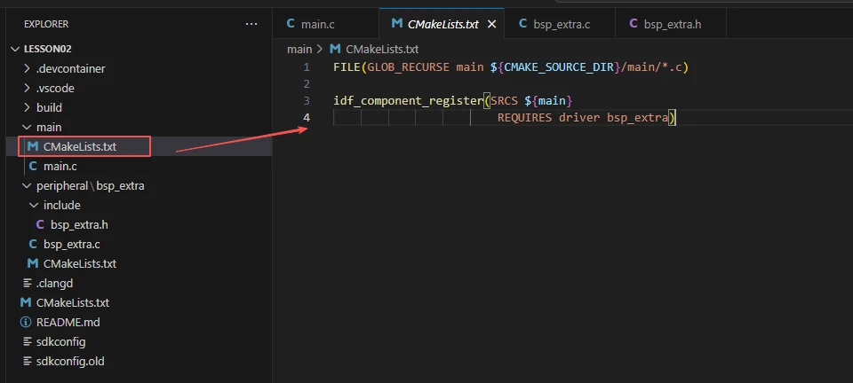
Now let's take a look at the CMakeLists.txt file in the main directory.
The function of this CMake configuration is as follows:
Collect all the .c source files in the main/ directory as the source files for the component;
Register the main component with the ESP-IDF build system and declare that it depends on the driver (an internal driver of ESP-IDF) and the custom component bsp_extra;
This way, during the build process, ESP-IDF knows to build bsp_extra first, and then build main.
Note: In the subsequent courses, we will not start from scratch to create a new CMakeLists.txt file. Instead, we will make some minor modifications to this existing file to integrate other drivers into the main function.
Complete Code
Kindly click the link below to view the full code implementation.
GitHub Link
Programming Steps
Now the code is ready. Next, we need to flash the ESP32-P4 so that we can observe the results.
First, we connect the Advance-P4 device to our computer host via the USB cable.

Here, following the steps in the first section, we first select the ESP-IDF version, the code upload method, the serial port, and the chip to be used.
Then here we need to configure the SDK.
Click the icon in the picture below.
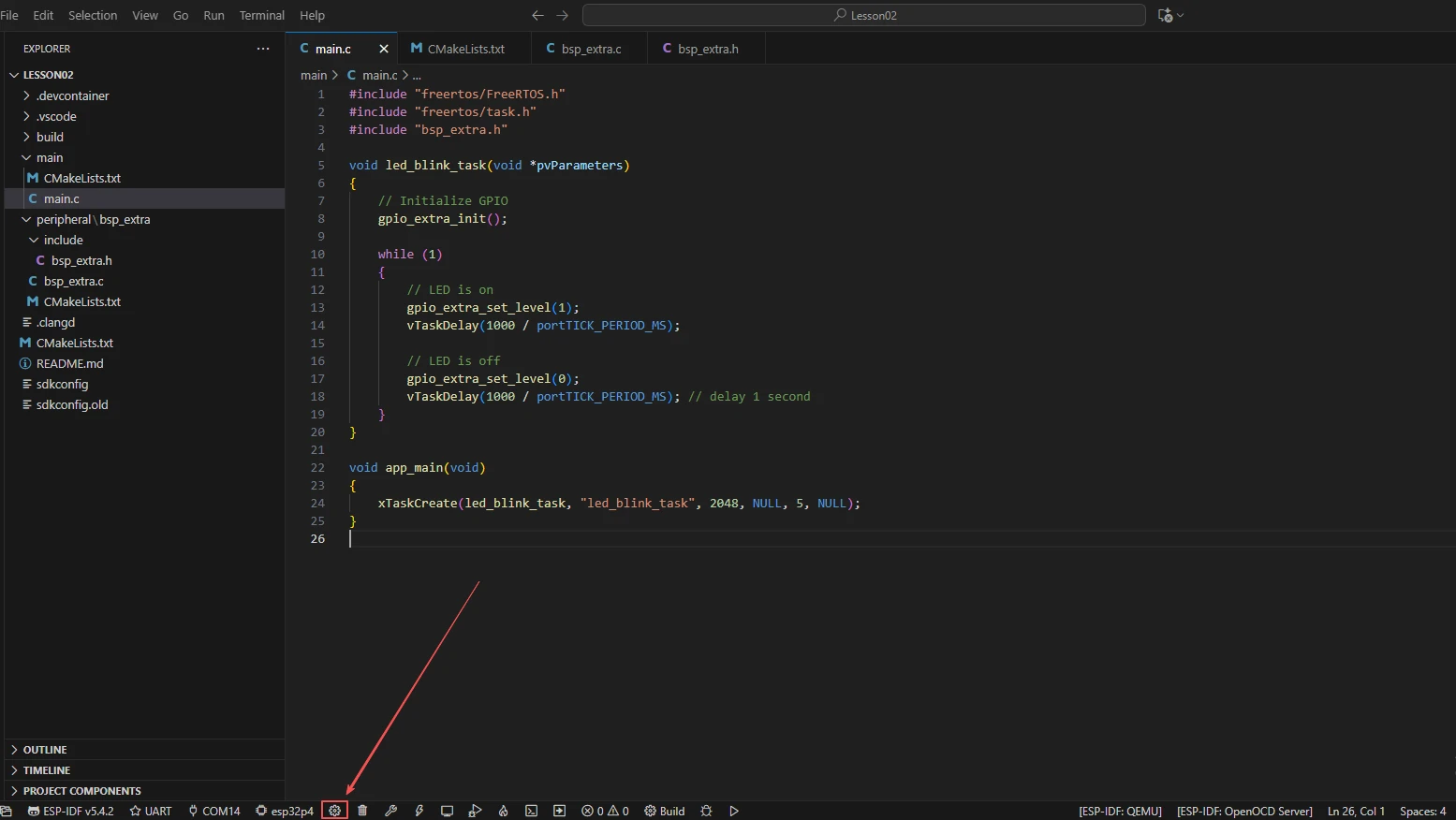
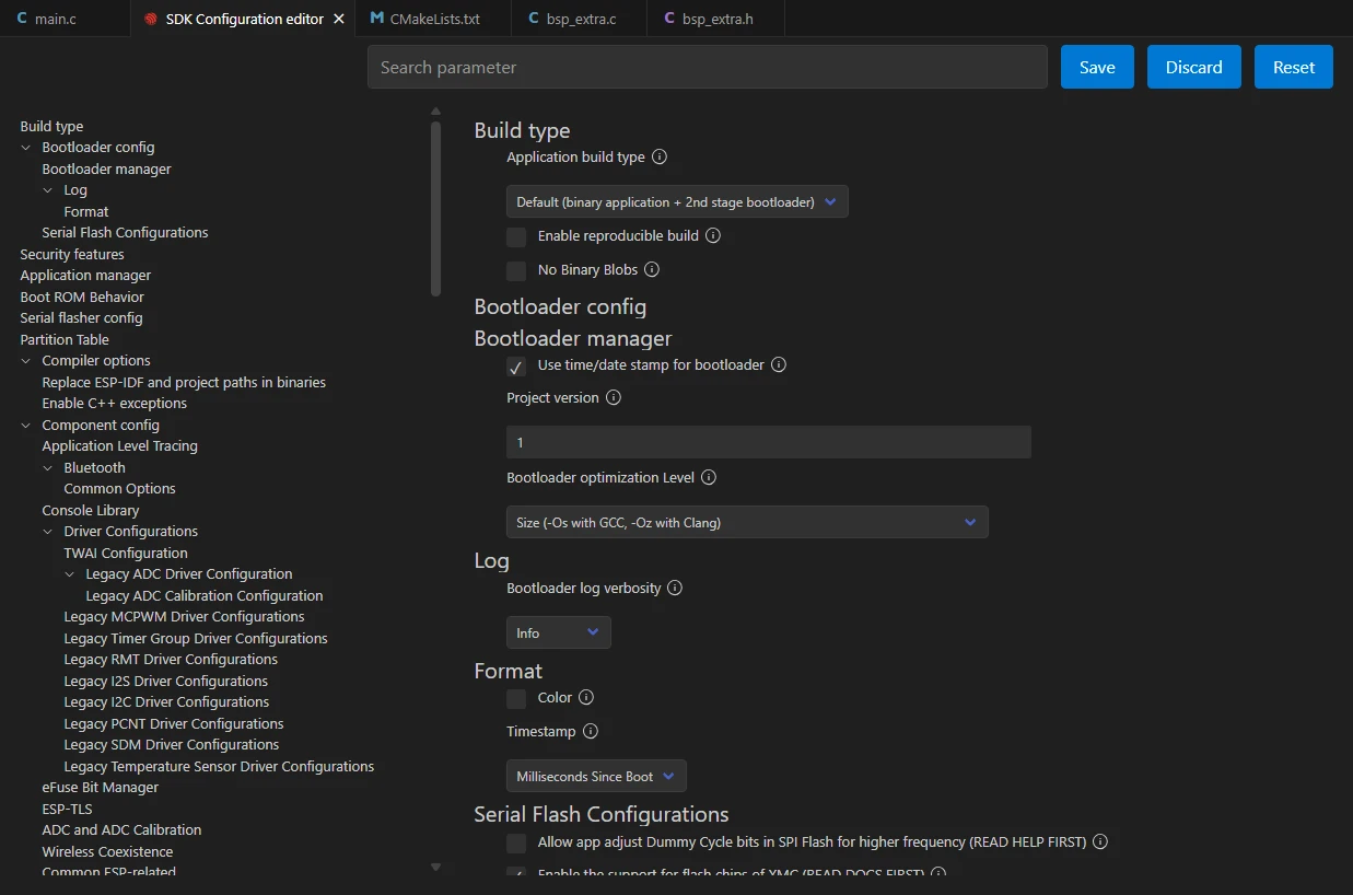
Wait for a moment for the loading process to complete, and then you can proceed with the relevant SDK configuration.
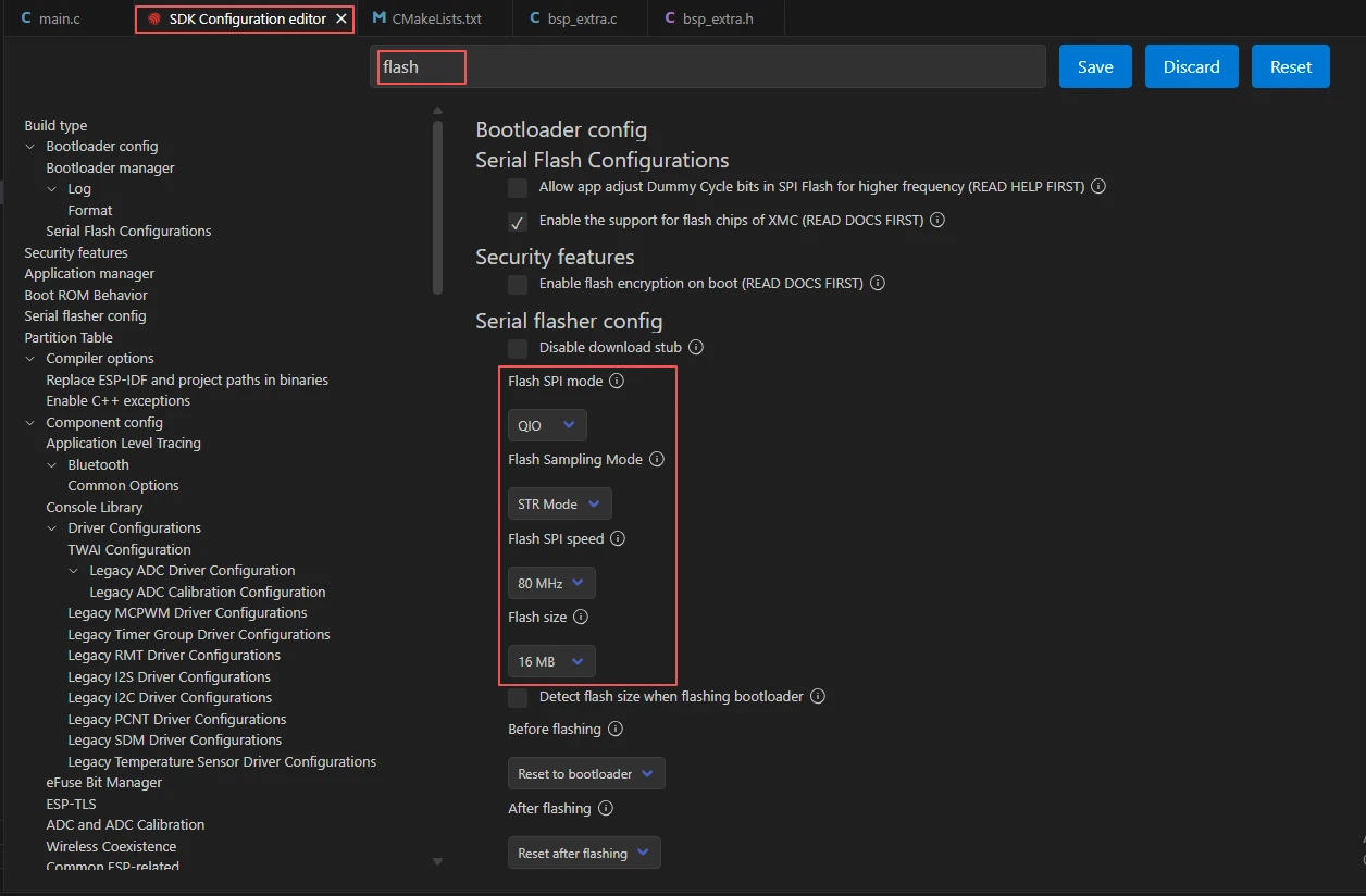
Then, search for "flash" in the search box.
(Make sure your flash settings are the same as mine.)
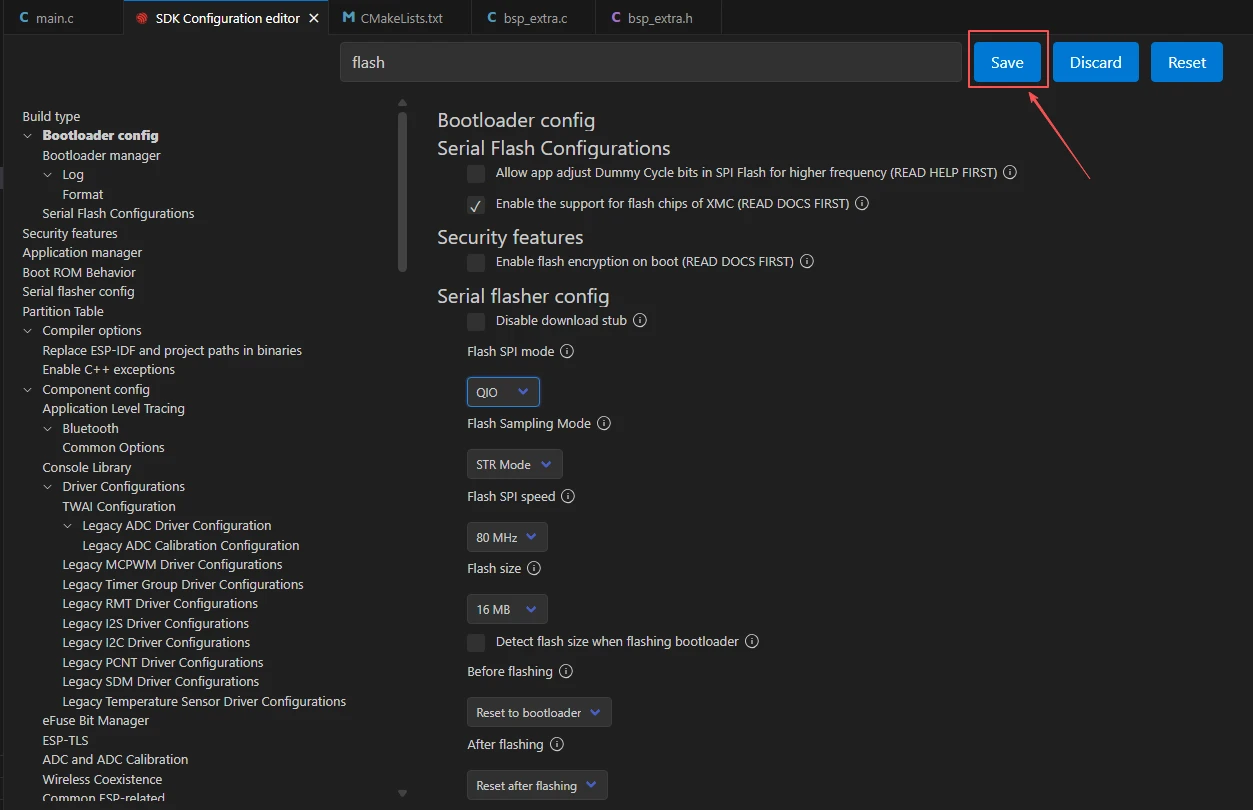
After the configuration is completed, remember to save your settings.
After that, we will compile and burn the code (which was explained in detail in the first class)

After waiting for a while, you will be able to see the LED connected to UART1 on your Advance-P4 turning on and off, remaining off for one second, and repeating this process over and over again.