Lesson04---Serial port usage
Introduction
In this class, we will start teaching you how to use the serial port component. We will communicate with the Wi-Fi serial module through the UART1 interface on the Advance-P4. The Advance-P4 connects to the Wi-Fi module via the serial port. After sending the AT command to the Wi-Fi module, it enables the Wi-Fi module to connect to the Wi-Fi network.
Hardware Used in This Lesson
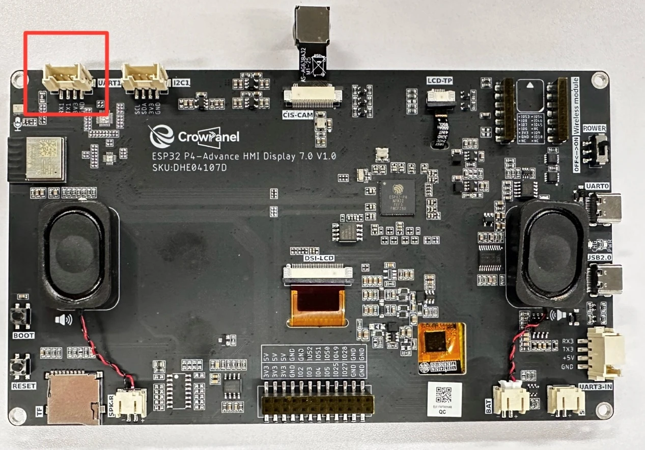
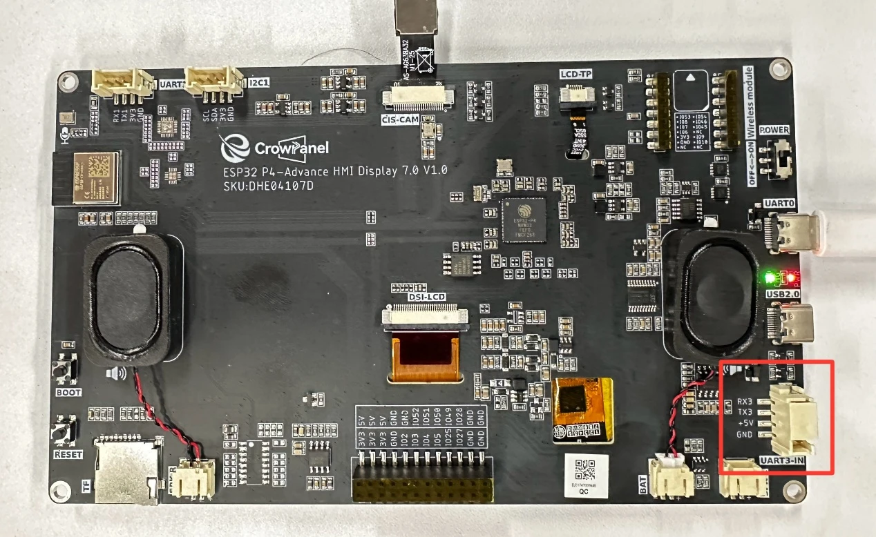
The UART1 interface on the Advance-P4

Operation Effect Diagram
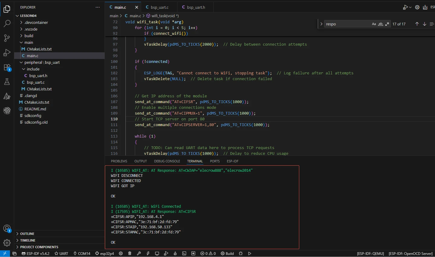
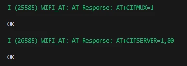
After running the code, you will be able to see the AT commands you sent on the monitor of ESP-IDF, as well as the responses returned to you by the Wi-Fi module via the serial port. (Green represents the Advance-P4's sending, and white represents the responses from the Wi-Fi module)
Key Explanations
The main focus of this class is on how to use the serial port. Here, we will provide everyone with a new component called bsp_uart. This component is mainly used for initializing the serial port, configuring the serial port, and providing related interface usage. As you know, you can call the interfaces we have written at the appropriate time.
Next, we will focus on understanding the bsp_uart component. First, click on the Github link below to download the code for this lesson.
GitHub Link
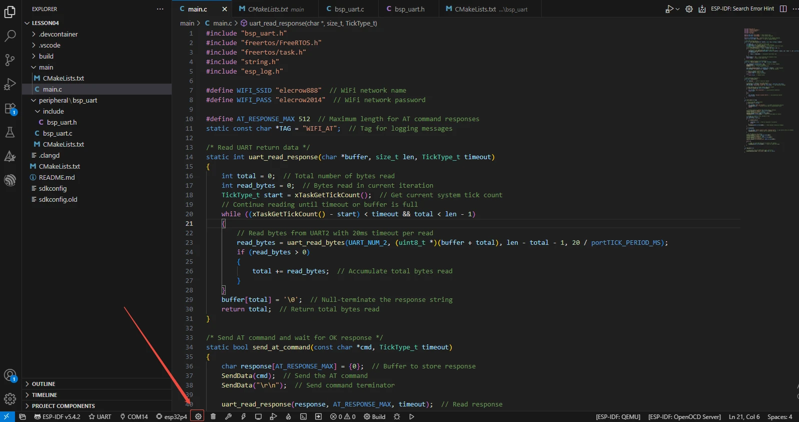
Then, drag the code of this lesson into VS Code and open the project file.
After opening it, you can see the framework of this project.
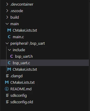
In the example of this class, a new folder named "bsp_uart" was created under the "peripheral" directory. Inside the "bsp_uart" folder, a new "include" folder and a "CMakeLists.txt" file were created.
The "bsp_uart" folder contains the "bsp_uart.c" driver file, and the "include" folder contains the "bsp_uart.h" header file.
The "CMakeLists.txt" file will integrate the driver into the build system, enabling the project to utilize the serial communication functionality written in "bsp_uart.c".
Serial port communication code
The driver code for serial port communication consists of two files: "bsp_uart.c" and "bsp_uart.h".
Next, we will first analyze the "bsp_uart.h" program.
"bsp_uart.h" is a header file for serial port communication, mainly used to:
Declare the functions, macros, and variables implemented in "bsp_uart.c" for external programs to use
Enable other .c files to call this module simply by including "#include "bsp_uart.h""
In other words, it is the interface layer, exposing which functions and constants can be used externally, while hiding the internal details of the module.
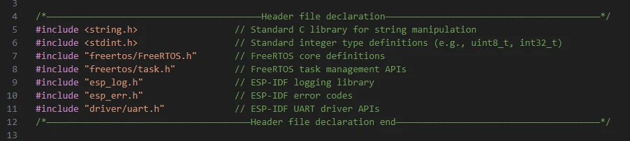
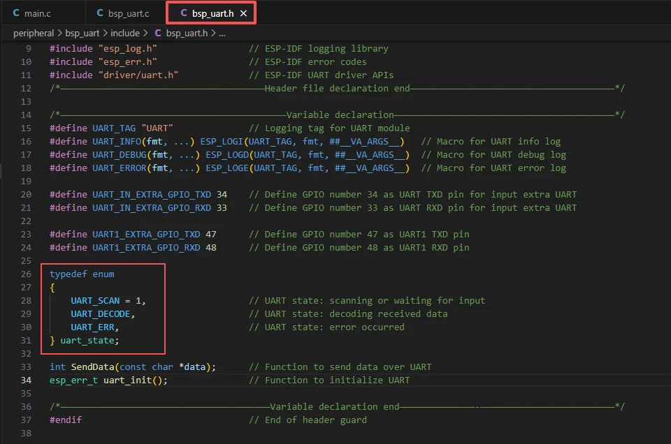
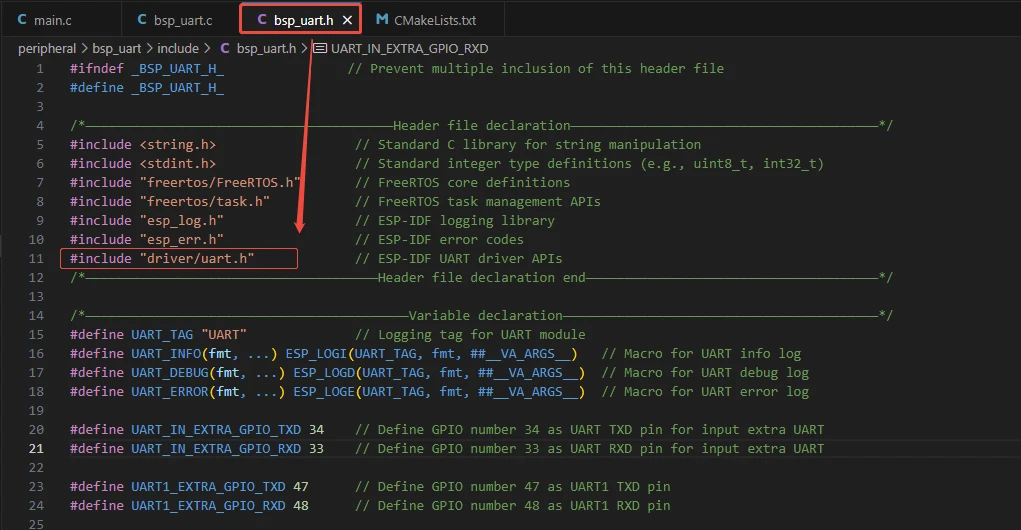
In this component, all the libraries we need to use are placed in the "bsp_uart.h" file for centralized management.
Then comes the declaration of the variables we need to use, as well as the declaration of the functions. The specific implementations of these functions are in "bsp_uart.c".
They are all uniformly placed in "bsp_uart.h" for ease of calling and management. (When they are used in "bsp_uart.c", we will understand their functions.)
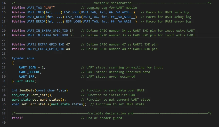
We can see that there are two sets of serial port pins here. The first set is UART_IN, which are the TX and RX pins of the UART3-IN interface, as shown in the figure. (This was not used in this lesson. We provided these pins to facilitate your future use. However, it should be noted that this interface cannot supply external power.)

The other group is the UART1 interface used in this class. As we mentioned before, this interface can not only be used as a regular GPIO port, but also as a serial port. This class will be using this interface.

Let's take a look at "bsp_uart.c" again, and see what each function specifically does.
bsp_uart: The bsp_uart component encapsulates the ESP32 UART hardware and provides unified interfaces for initialization, data transmission, reception, and status management, shielding the details of the underlying driver, enabling upper-layer tasks (such as WiFi AT control tasks) to communicate with external devices through UART stably and reliably.
Then the following functions are the interfaces we call to implement screen display.
uart_init():
This function is responsible for initializing UART2 of ESP32-P4 and configuring its communication parameters, including baud rate, data bits, stop bits, parity bits, and flow control mode. It also installs the UART driver and specifies the TX/RX pins.
By encapsulating the underlying uart_driver_install(), uart_param_config(), and uart_set_pin(), it shields the hardware details, allowing the upper-layer tasks to not need to worry about the cumbersome operations of UART initialization.
After calling this function, the UART hardware is ready and can perform data transmission and reception. It is usually called during system startup or before communication is needed.
There are a total of 3 serial port interfaces on our Advance-P4, namely UART0, UART1, and UART3-IN.
UART0 is our default interface for power supply and uploading code. By default, it is UART_NUM_0.
Then there are UART_NUM_1 and UART_NUM_2 left.
Here, we can choose either of these two ports as we like, because we only use one serial port interface here. So I choose UART_NUM_2.
If you also use the UART3-IN interface, make sure that the port number and pin you bind correspond and do not conflict.
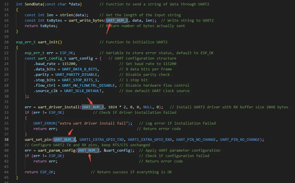
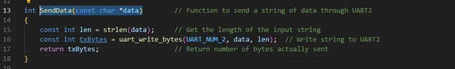
SendData(const char *data):
This function is used to send string data to UART2. It first calculates the length of the string, and then calls uart_write_bytes() to send the data to the UART hardware. The function returns the actual number of bytes sent, which is convenient for the upper layer to determine whether the transmission was successful. It encapsulates the underlying driver interface, allowing upper-level tasks or modules to safely send commands or data by simply calling SendData(), without having to handle the buffer and byte length every time.
That's all about the components of bsp_uart. Just make sure you know how to call these interfaces.
Then, if we need to make a call, we must also configure the "CMakeLists.txt" file located in the "bsp_uart" folder.
This file is placed in the "bsp_uart" folder and its main function is to inform the build system (CMake) of ESP-IDF: how to compile and register the "bsp_uart" component.
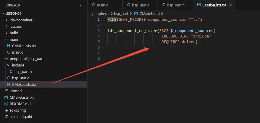
The reason why this is called "driver" is that we have called it in the "bsp_uart.h" file (for other libraries that are system libraries, there is no need to add anything).
Main function
The main folder is the core directory for program execution, and it contains the executable file main.c for the main function.
Add the main folder to the "CMakeLists.txt" file of the build system.
This is the entry file for the entire application. In ESP-IDF, there is no int main(), but the program starts running from void app_main(void).
In the ESP-IDF framework, app_main() is the main entry point of the entire program, equivalent to the main() function in standard C.
When the ESP32-P4 powers on or restarts, the system will execute app_main() to start the user tasks and application logic.
Let's explain main.c
Function: Calls the interfaces in the bsp_uart component to allow the FreeRTOS scheduler to run the wifi_task, and send AT commands to control the wifi module to connect to the wifi.
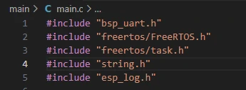
"bsp_uart.h":
This file imports the custom UART encapsulation component "bsp_uart", providing interfaces such as UART initialization, data transmission, data reception, and status management, enabling upper-layer tasks to conveniently communicate with external devices via UART.
include "freertos/FreeRTOS.h":
This file imports the basic header file of the FreeRTOS kernel, providing basic operation functions and type definitions such as task scheduling, time management, semaphores, and queues, which are necessary for using FreeRTOS.
include "freertos/task.h":
This file imports the interfaces related to task management in FreeRTOS, including functions such as xTaskCreate() for creating tasks, vTaskDelay() for task delay, and vTaskDelete() for task deletion, used for multi-task scheduling and management.
include "string.h":
This file imports the string processing functions of the C standard library, such as strlen(), strstr(), and snprintf(), for string length calculation, substring search, and string formatting operations.
include "esp_log.h":
This file imports the logging system interface provided by ESP-IDF, used for printing debug information, error information, and system status. It provides functions such as ESP_LOGI(), ESP_LOGE(), and ESP_LOGD().
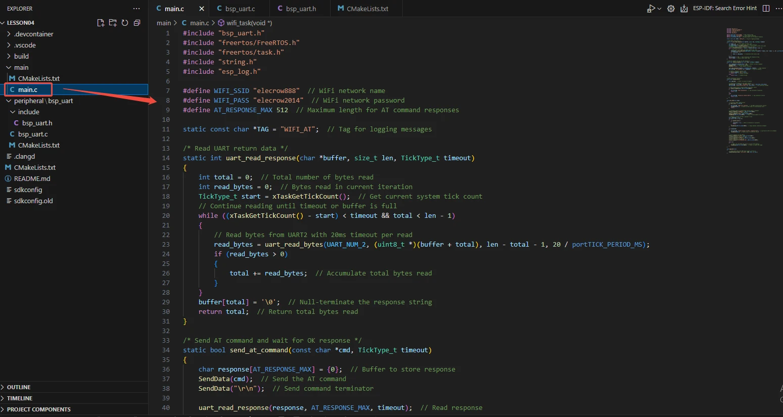
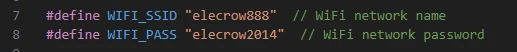
The name (SSID) of the WiFi was defined, which is used in the program to construct AT commands to enable the module to connect to the specified WiFi network.
The password (Password) of the WiFi was also defined, which, along with the SSID, is used in the AT commands to connect to the WiFi network.
Define a constant to represent the maximum length of the buffer for receiving AT command responses, which is 512 bytes. This ensures that the received data will not exceed the boundary.
Define a static string as the log tag (Tag), which is used by log functions such as ESP_LOGI() and ESP_LOGE() to distinguish the outputs of different modules, facilitating debugging and problem location.

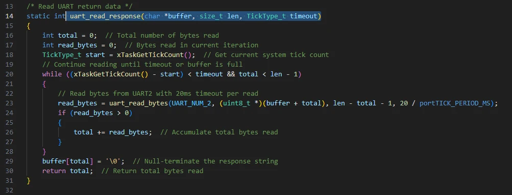
uart_read_response(char *buffer, size_t len, TickType_t timeout):
The 'uart_read_response()' function is the core function in the bsp_uart component for receiving data from the UART. It repeatedly calls the ESP32's 'uart_read_bytes()' interface to store the data received by UART2 into the buffer provided by the user. It also supports timeout control.
The function accumulates the actual received bytes each time it reads and adds \0 at the end of the buffer to ensure that the returned data is a valid C string. It not only prevents buffer overflow but also continuously waits for data within the specified time, making it suitable for reading AT command responses or other data returned by external devices. This enables upper-level tasks to safely and reliably obtain the received data without directly operating the underlying UART driver.
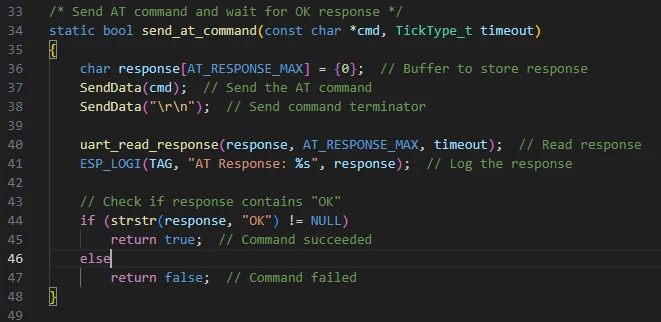
send_at_command(const char *cmd, TickType_t timeout):
The 'send_at_command()' function is a high-level wrapper function in the 'bsp_uart' component, used to send commands to the AT module and wait for a response.
It first sends the AT instruction passed by the user to the UART using the 'SendData()' function, and then sends a carriage return and line feed character as the command terminator; then it calls 'uart_read_response()' to read the data returned by the module and save it in the buffer, while also printing the log for debugging purposes.
The function checks if the returned string contains "OK". If it does, it means the command execution was successful and returns 'true'; otherwise, it returns 'false' indicating a command failure.
This function encapsulates the complete process of sending, receiving and result judgment, enabling the upper-level tasks to safely and simply operate the AT module through a single interface, without having to deal with the details of the underlying UART reading and writing as well as response parsing.
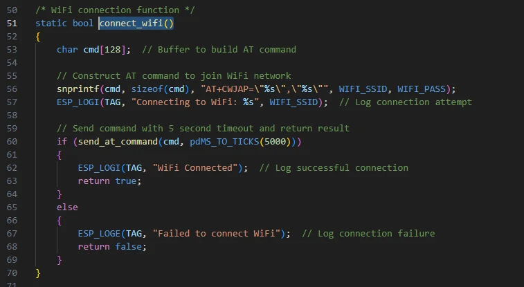
connect_wifi():
The 'connect_wifi()' function is a high-level encapsulation function used to enable the ESP32 to connect to a specified WiFi network through the AT module.
First, it builds the AT command for connecting to WiFi, "AT+CWMODE=1, 'SSID', 'PASSWORD'", in a 128-byte buffer and prints a log message indicating that the WiFi name is being attempted to connect.
Then, it calls the 'send_at_command()' function to send the command and waits for the module's response, setting the timeout to 5 seconds.
The function determines whether the connection was successful based on the response result: if the response is "OK", it prints the "WiFi Connected" log and returns true; if the connection was not successful, it prints an error log and returns false.
This function encapsulates the complete process from building the AT command, sending the command to judging the connection result, allowing the upper-level tasks to directly call it to achieve WiFi connection without handling the underlying UART and command parsing details.
wifi_task(void *arg):
This function calls all the interfaces we discussed earlier.
The function wifi_task() is a FreeRTOS task that communicates with the AT WiFi module via UART to achieve WiFi connection and initialization of the TCP server.
The task first initializes the UART; if it fails, it deletes itself to ensure system stability;
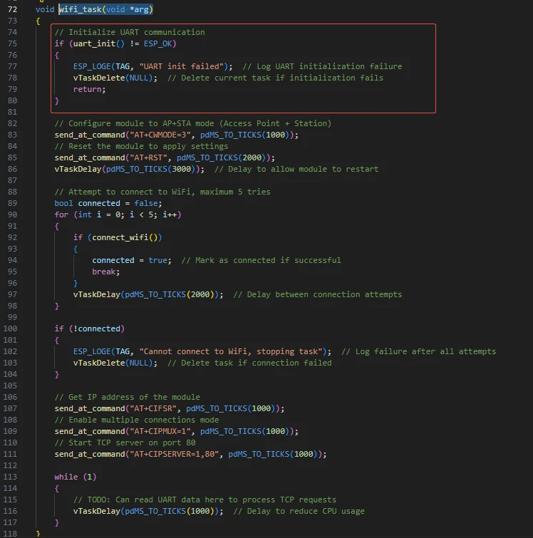
Then set the module to the AP + STA mode and reset it to make the configuration take effect.
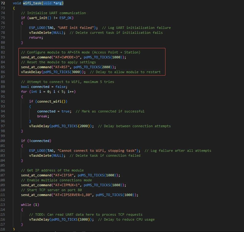
Then, the process will repeatedly attempt to connect to the specified WiFi, up to 5 times. Each failure will cause a 2-second delay. If the connection is still unsuccessful in the end, an error message will be printed and the task will be deleted.
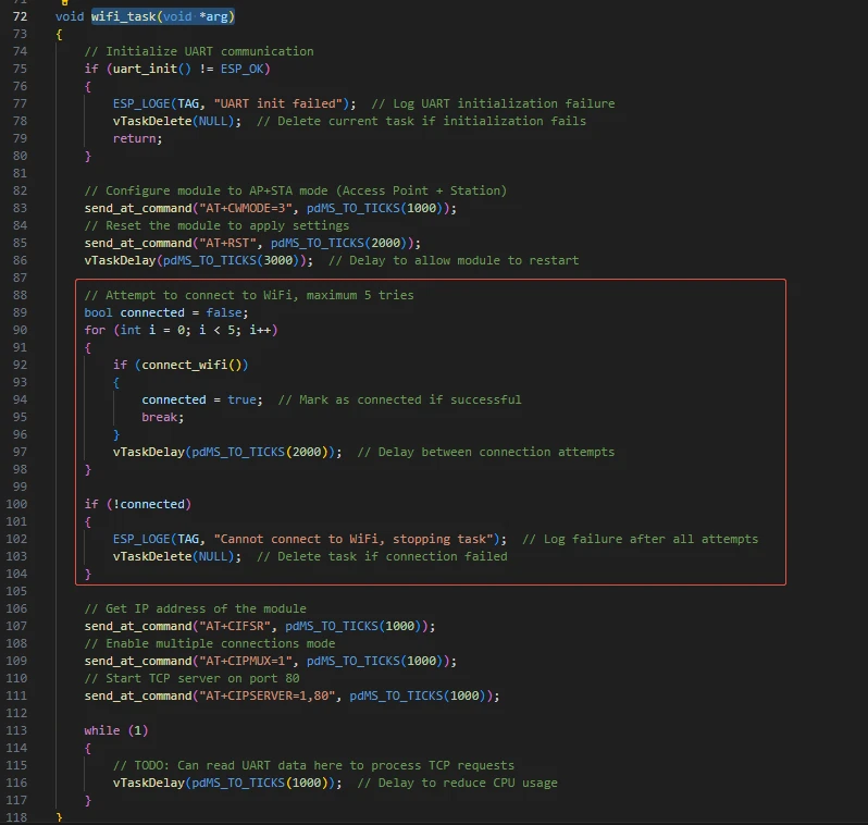
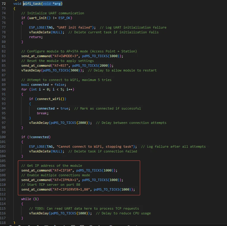
After the connection is successful, it obtains the module's IP address,enables the multi-connection mode, and starts the TCP server to listen on port 80.
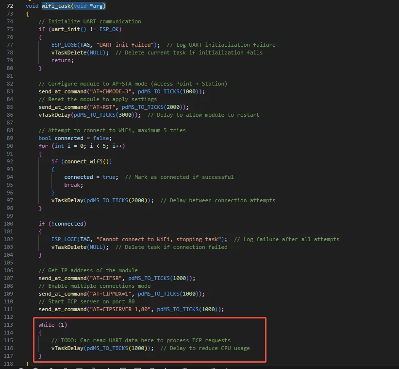
Finally, it enters an infinite loop, retaining the interface for subsequent processing of TCP requests, and reducing CPU usage through delay, thereby completing the entire process of WiFi network management and services.
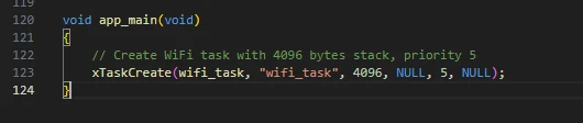
Then comes the main function app_main.
app_main() is the entry function of the ESP-IDF program, similar to the main() function in a standard C program. In this code, its role is very clear: it calls xTaskCreate() to create a FreeRTOS task named "wifi_task", with the task function being wifi_task, allocating 4096 bytes of stack space, having a priority of 5, not passing any task parameters, and setting the task handle to NULL (not saving the task handle).
The core meaning of this line of code is to encapsulate the WiFi initialization and TCP server logic into an independent task that runs under the management of the FreeRTOS scheduler. This keeps the main program entry point simple while ensuring that the WiFi connection task can be executed in parallel without blocking other tasks.
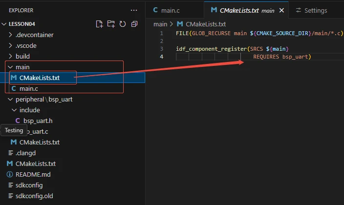
Now let's take a look at the "CMakeLists.txt" file in the "main" directory.
The function of this CMake configuration is as follows:
Collect all the .c source files in the "main/" directory as the source files for the component;
Register the "main" component with the ESP-IDF build system and declare that it depends on the custom component "bsp_uart".
This way, during the build process, ESP-IDF knows to build "bsp_uart" first, and then build "main".
Note: In the subsequent courses, we will not start from scratch to create a new "CMakeLists.txt" file. Instead, we will make some minor modifications to this existing file to integrate other drivers into the main function.
Complete Code
Kindly click the link below to view the full code implementation.
GitHub Link
Programming Steps
Now the code is ready. Next, we need to flash the ESP32-P4 so that we can observe the results.
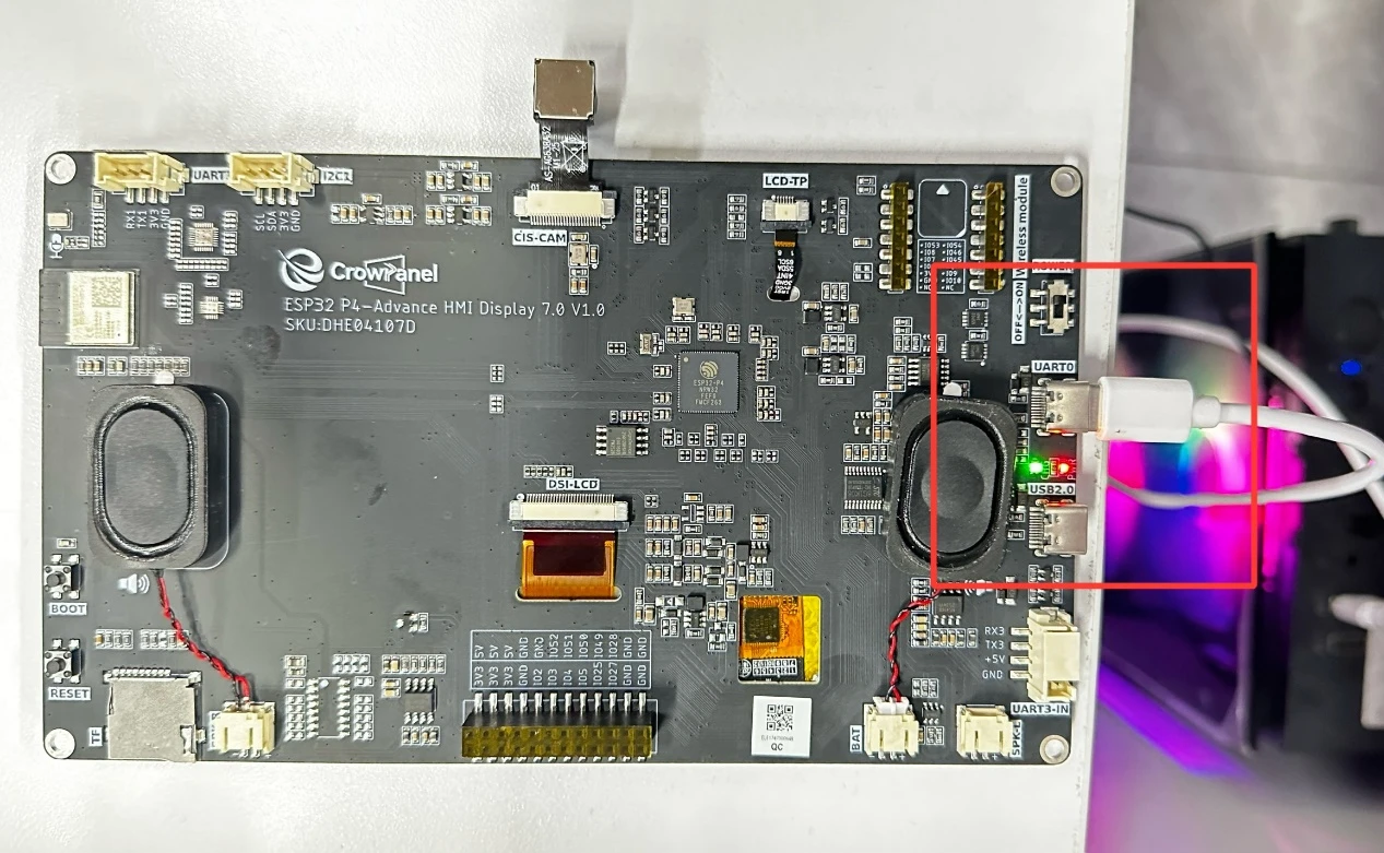
First, we connect the Advance-P4 device to our computer host via the USB cable.
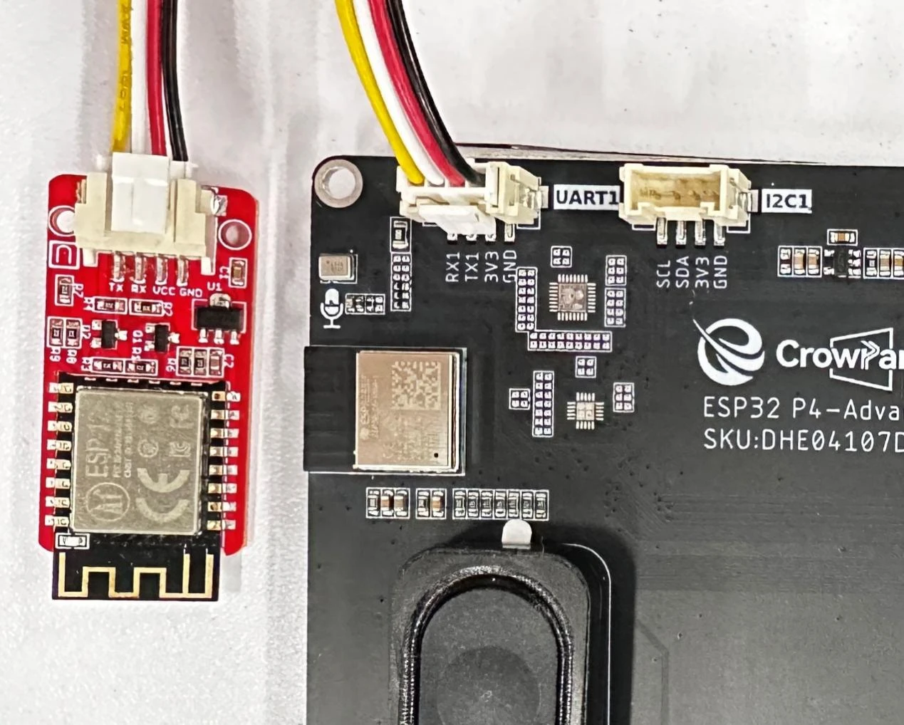
Then, connect an ESP8266 wifi module to the UART1 interface.
(Connect the VCC of UART1 interface to the VCC pin of the wifi module)
(Connect the GND of UART1 interface to the GND pin of the wifi module)
(Turn the TX of UART1 interface to the RX pin of the wifi module) (Cross connection)
(Turn the RX of UART1 interface to the TX pin of the wifi module) (Cross connection)
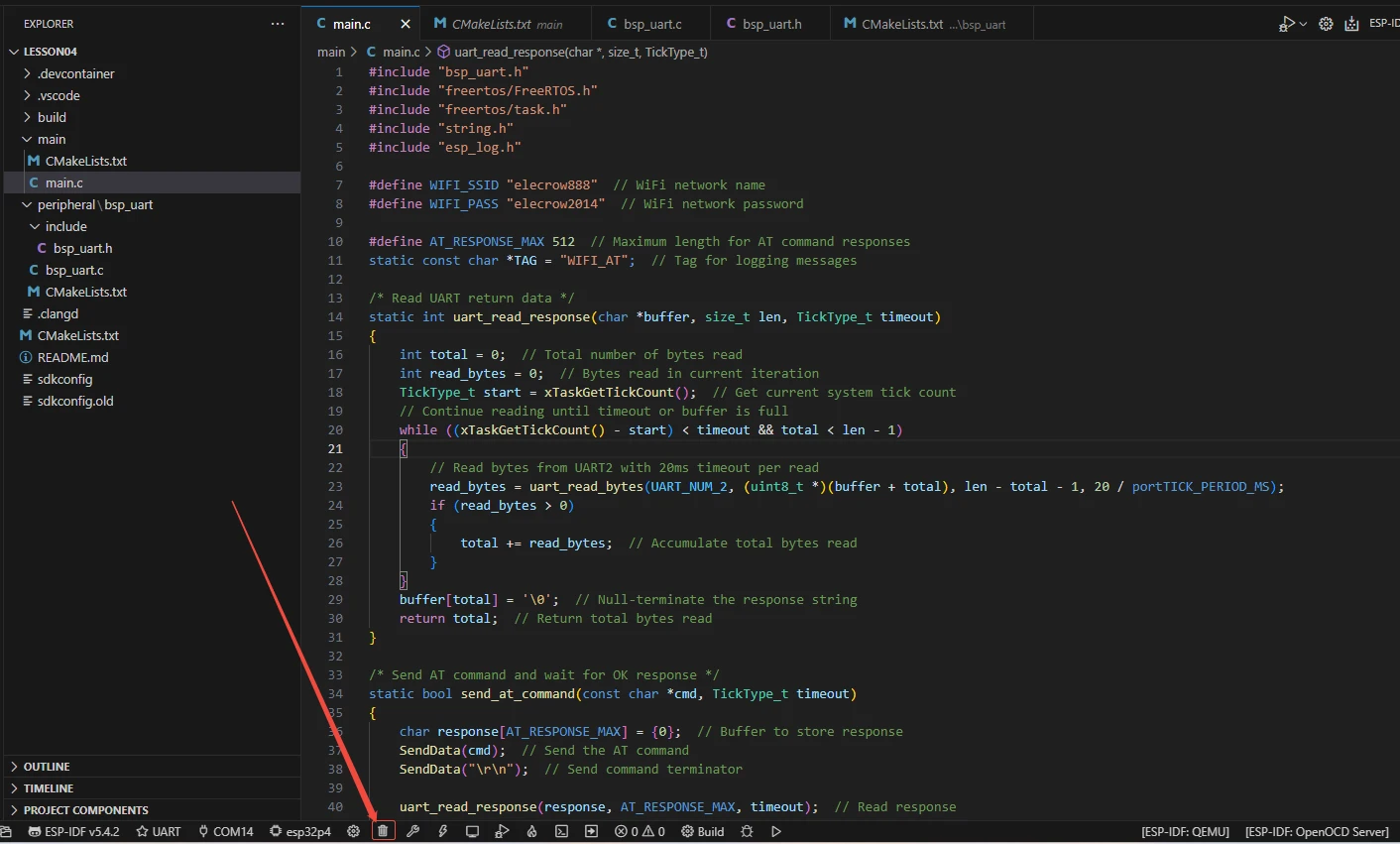
Before starting the burning process, delete all the compiled files and restore the project to its initial "uncompiled" state. (This ensures that the subsequent compilation will not be affected by your previous actions.)
Here, following the steps in the first section, we first select the ESP-IDF version, the code upload method, the serial port, and the chip to be used.
Then here we need to configure the SDK.
Click the icon in the picture below.
Wait for a moment for the loading process to complete, and then you can proceed with the relevant SDK configuration.
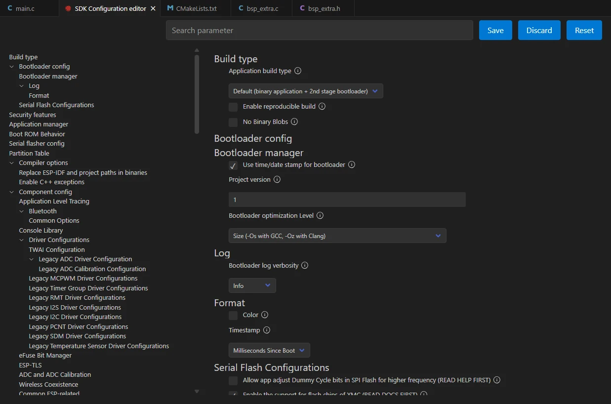
Then, search for "flash" in the search box.
(Make sure your flash settings are the same as mine.)

After the configuration is completed, remember to save your settings.
After that, we will compile and burn the code (which was explained in detail in the first class)
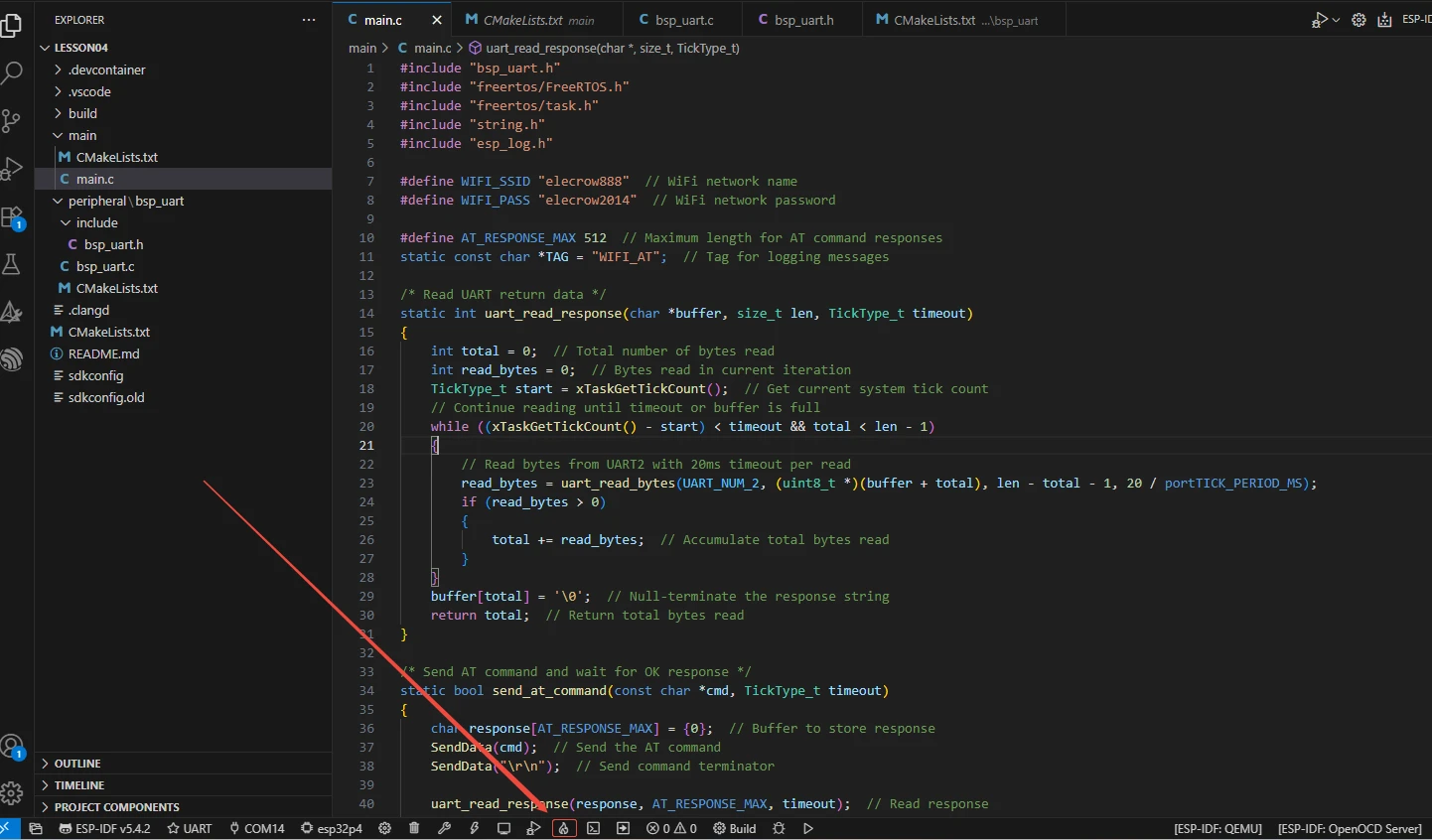
Here, we would like to introduce to you another very convenient feature. With just one button press, you can perform the tasks of compiling, uploading, and opening the monitor all at once. (The prerequisite is that the entire code is error-free.)
After waiting for a while, the code compilation and upload were completed, and the monitor also opened.
After burning the code, you will be able to see the AT commands you sent through the monitor on ESP-IDF, as well as the responses returned to you by the wifi module via the serial port. (Green is sent by Advance-P4, and white is the response from the wifi module)