Lesson05--- Touchscreen
Introduction
In this class, we will gradually start to use multiple components together. We hope this will help everyone gain a deeper understanding of ESP-IDF and ESP32-P4.
In this class, we will use two components from the Advance-P4 category, namely bsp_display and bsp_i2c, to enable the screen to be touchable, and you will also be able to see the coordinates of your touch through the monitor.
Hardware Used in This Lesson
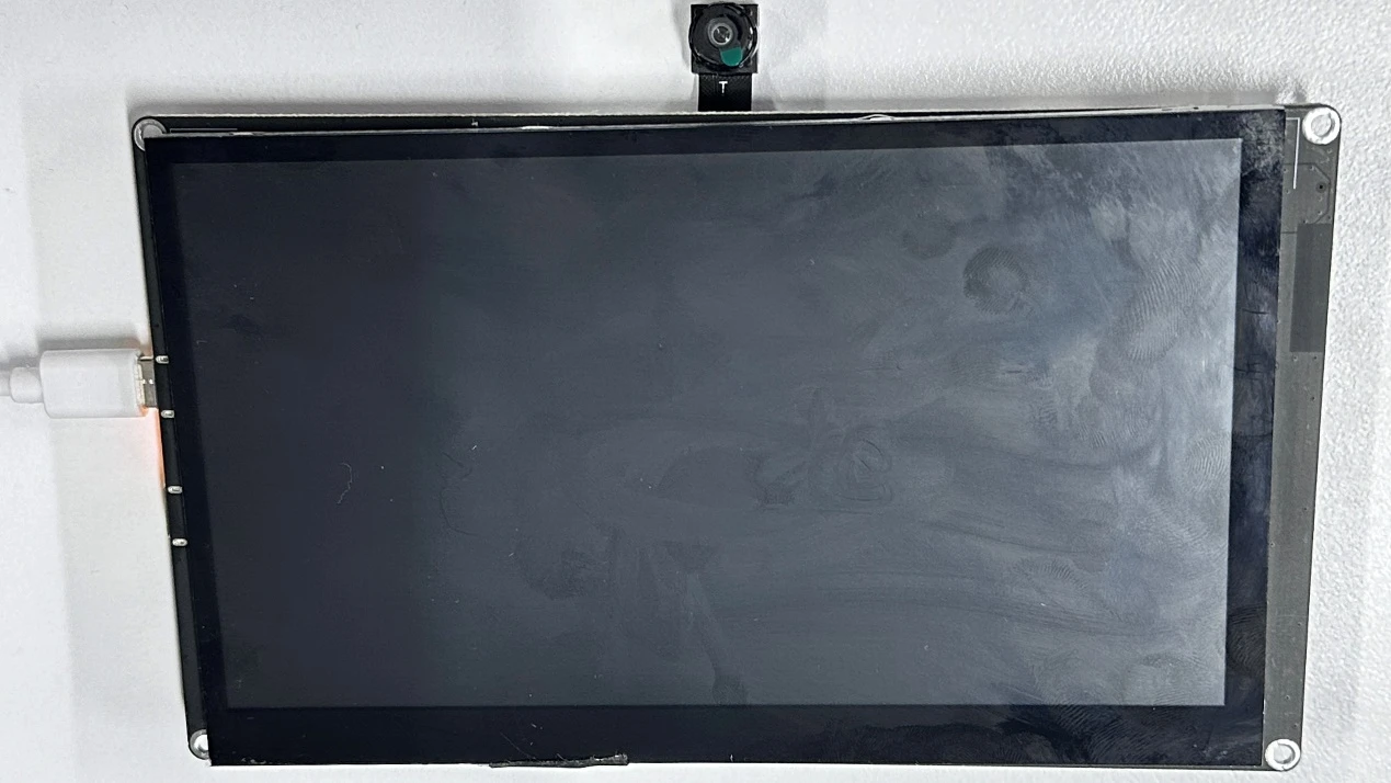
The touchscreen on the Advance-P4
Touchscreen schematic diagram

First, let's look at the Touchscreen Sensor and Electrostatic Field sections. Inside the touchscreen sensor, there is a grid-like electrode structure composed of conductive layers. These electrodes interact with each other, forming a uniform electrostatic field in the screen area. When a finger touches the screen, since the human body is conductive, the finger will form a new capacitance with the conductive layer on the screen. The appearance of this capacitance will interfere with the originally uniform electrostatic field, causing a significant distortion in the distribution of the electrostatic field in the area near the touch point, and subsequently resulting in changes in the capacitance value of the electrodes in that area.
Then, we come to the core function of the Controller. The GT911 takes on this role as the controller. It continuously scans all the electrodes on the touchscreen and precisely detects the changes in the capacitance of each electrode. Based on the detected data of the different capacitances of the electrodes, the GT911 runs a specific algorithm internally, analyzing these data to calculate the X and Y coordinates of the touch point on the screen, which is the coordinate detection process illustrated in the diagram as "Controller Detects Touch Location".
After that, the GT911 sends the calculated touch point coordinate information to the connected main processor (such as an ESP32 microcontroller) according to the pre-set communication protocol (such as I2C, SPI, etc.).
Finally, the main processor receives the coordinate data and further processes and parses these data using software.
At the same time, in combination with the "Device Instructions" (device instruction logic), the software maps and correlates the touch coordinates with specific elements in the device interface (such as buttons, sliders, etc.). Thus, when the user touches the screen, the device can accurately identify whether it is clicking a button, sliding the screen, or other operations, and make corresponding interaction responses, thereby achieving smooth touch interaction functionality.
Operation Effect Diagram
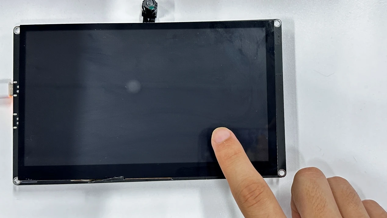
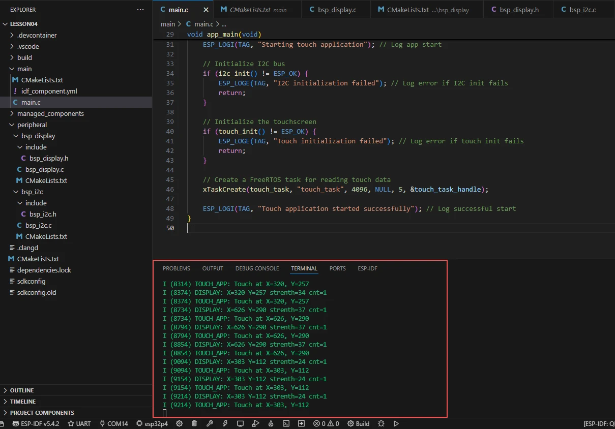
After running the code, you will be able to see the coordinates returned by the ESP32-P4 to you through the monitor on the ESP-IDF at the moment when you touched the screen.
Key Explanations
Now there are two components in this class (bsp_display and bsp_i2c). How should we handle the overall framework?
It's actually not difficult. Once you understand how one component is used, the two components are similar. First, click on the Github link below to download the code for this lesson.
GitHub Link
Then, drag the code of this lesson into VS Code and open the project file.
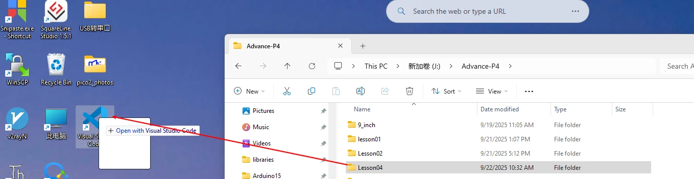
After opening it, you can see the framework of this project.
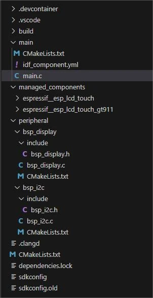
In the example of this class, a new folder named "bsp_display" was created under the "peripheral" directory. Inside the "bsp_display" folder, a new "include" folder and a "CMakeLists.txt" file were created.
The "bsp_display" folder contains the "bsp_display.c" driver file, and the "include" folder contains the "bsp_display.h" header file.
The "CMakeLists.txt" file integrates the driver into the build system, enabling the project to utilize the touchscreen functionality written in "bsp_display.c".
Screen touch driver code
The screen touch driver consists of two files: "bsp_display.c" and "bsp_display.h".
Next, we will first analyze the "bsp_display.h" program.
"bsp_display.h" is a header file for the display and touch screen driver module, mainly used for:
Making the functions, macros, and variable declarations implemented in "bsp_display.c" available for use by external programs
Allowing other .c files to simply include "bsp_display.h" to call this module
In other words, it is the interface layer, exposing which functions and constants can be used externally, while hiding the internal details of the module.
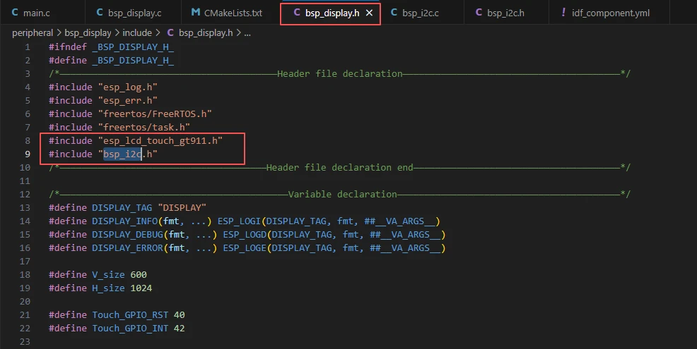
In this component, all the libraries we need to use are placed in the "bsp_display.h" file for centralized management.

Such as esp_lcd_touch_gt911.h

In this case, we need to fill in the version of esp_lcd_touch_gt911 in the idf_component.yml file located in the main folder. Since this is an official library, we need to use the official library to achieve the touch function of the GT911 screen on our Advance-P4.
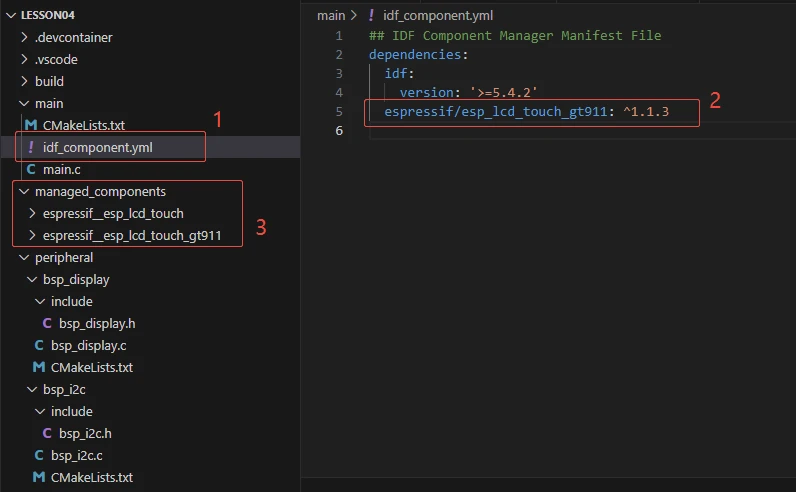
When the project is compiled in the future, it will download the esp_lcd_touch_gt911 library version 1.1.3. After the download, these network components will be saved in the "managed_components" folder. (This is automatically generated after filling in the version number.)
Then we will return to the "bsp_display.h" file.
We can see that the "bsp_i2c.h" file is also included in it.

This is another component that we are using in this class.

Because our GT911 screen touch driver uses I2C for communication control.
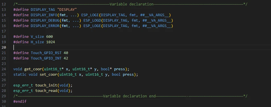
Then, we declare the variables we need to use, as well as the functions. The specific implementation of these functions is in "bsp_display.c".
They are all unified in "bsp_display.h" for ease of calling and management.
Let's take a look at "bsp_display.c" again, and see what each function does specifically.
set_coor:
This is an internal utility function used to update the global variables touch_x, touch_y, and is_pressed, recording the latest touch point coordinates and press status. It is not called externally and is only used within this file to store touch data.
get_coor:
This is an external interface function used to return the current touch point coordinates and press status to the caller. By calling this function, upper-level applications can know the latest coordinates of the touch screen and whether it is pressed.
touch_init:
If you need to use the screen touch functionality, you must call this function in the main function.
This is the touch screen initialization function. Its main function is to configure the I2C bus and the parameters of the GT911 touch chip, and then create the handle of the touch screen driver. If the main I2C address initialization fails, it will try the backup address to ensure that the GT911 can be correctly recognized and driven. If successful, it returns ESP_OK; if failed, it returns the corresponding error code.
touch_read:
This is the touch data reading function. Its main function is to read the raw data of the current touch point from the GT911, and then extract the touch point coordinates, intensity, and number of touch points.
If a touch is detected, it updates the global coordinates and prints debugging information; if no touch is detected, it sets the status to "invalid coordinates (0xffff, 0xffff) and not pressed". Finally, it returns ESP_OK or the error code.
This is the component of the screen touch function. Just know how to call these interfaces.
Then, if you need to call it, we must configure the "CMakeLists.txt" file in the bsp_display folder.
This file is placed in the bsp_display folder and its main function is to tell the build system (CMake) of ESP-IDF how to compile and register this component.
(Here, we will explain in detail the construction of this "CMakeLists.txt". In the future, we will only tell you how to add and delete those libraries and components.)
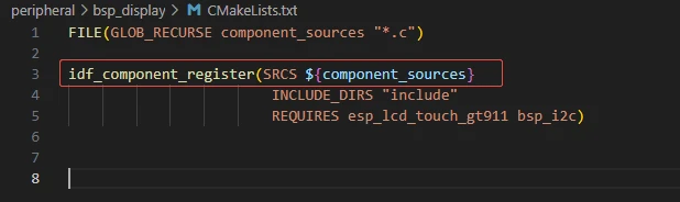
The following line of code will recursively search all the .c files in the current directory (and its subdirectories), and then place the results in the variable component_sources.
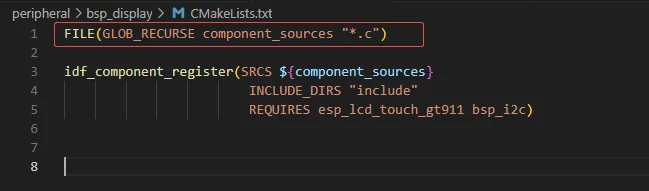
This is a macro provided by ESP-IDF, used to register a component.
SRCS specifies the source files that the component needs to be compiled. Here, it refers to all the .c files that were just found.
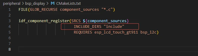
Specify the search path for header files.
It indicates that the header files in the "bsp_display/include" folder (such as "bsp_display.h") will be made available for use by other components.
This way, other components only need to #include "bsp_display.h" to find the header files.
Specify the other components that the bsp_display component depends on.
This means: Before compiling bsp_display, esp_lcd_touch_gt911 (the GT911 touch driver) and bsp_i2c (our own I2C wrapper) must be compiled first.
At the same time, the dependencies will be automatically added during linking.
(In the future, when we modify other projects, simply add or remove the relevant components.)
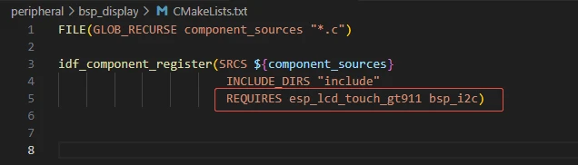
The reason why esp_lcd_touch_gt911 and bsp_i2c are used here is that we called them in the "bsp_display.h" file (if the other libraries are system libraries, then there is no need to add them)
I2C driver code
Now that the relevant content of the screen touch driver has been explained, let's take a look at the content related to the I2C component.
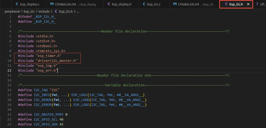
In "bsp_i2c.h", the same process is followed to declare and define the used libraries, variables, and functions, making it convenient to call them when using them.

In "bsp_i2c.c", the library, variables and functions in "bsp_i2c.h" are fully utilized to implement the related functions.
For the functions in "bsp_i2c.c", all you need to know is how to use them.
print_binary:
Converts a 16-bit integer to a binary string (16 bits, with leading 0s padded), mainly used for printing values in binary form during debugging.
print_byte:
Converts a byte (8 bits) to a string format like 0bXXXX YYYY (high 4 bits + low 4 bits), facilitating intuitive viewing of the binary content of the byte during debugging.
i2c_init:
Initializes the I2C bus: configures the I2C port, SDA/SCL pins, clock source, filtering parameters and pull-up resistors, then creates an I2C master bus handle (saved in the global variable i2c_bus_handle), preparing for subsequent device communication.
i2c_dev_register:
Registers a slave device on the I2C bus (based on the 7-bit device address), and returns the handle of the device. When reading from or writing to this device in the future, this handle needs to be passed in.
i2c_read:
Reads a certain number of data from the specified I2C device, and stores the result in the read_buffer. The underlying call is i2c_master_receive.
i2c_write:
Writes a certain number of data to the specified I2C device, the underlying call is i2c_master_transmit.
i2c_write_read:
First writes a register address to the I2C device (read_reg), then reads the data from the corresponding register (read_buffer). This is a common process for reading registers, used to "select" the register before reading the value.
i2c_read_reg:
Performs the operation of "writing register address + reading data" at once (implemented by calling i2c_master_transmit_receive), which is more concise than i2c_write_read.
i2c_write_reg:
Writes a byte data to a certain register of the I2C device (register address + data), often used for configuring peripheral register.
Let's talk about the role of the "CMakeLists.txt" file in the "bsp_i2c" folder.
This "CMakeLists.txt" is a build configuration file in the ESP-IDF framework used to manage the I2C driver components. Its main function is to tell the build system how to compile and integrate this I2C driver component.
As mentioned earlier, here we only need to modify the components and libraries we are using at this point.
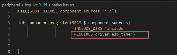
Here, in the "bsp_i2c.h" file, we have utilized "driver/i2c_master.h" and "esp_timer.h".
Main function
The main folder is the core directory for program execution, and it contains the executable file main.c for the main function.
Add the main folder to the "CMakeLists.txt" file of the build system.
This is the entry file of the entire application. In ESP-IDF, there is no "int main()", but the program starts running from "void app_main(void)".
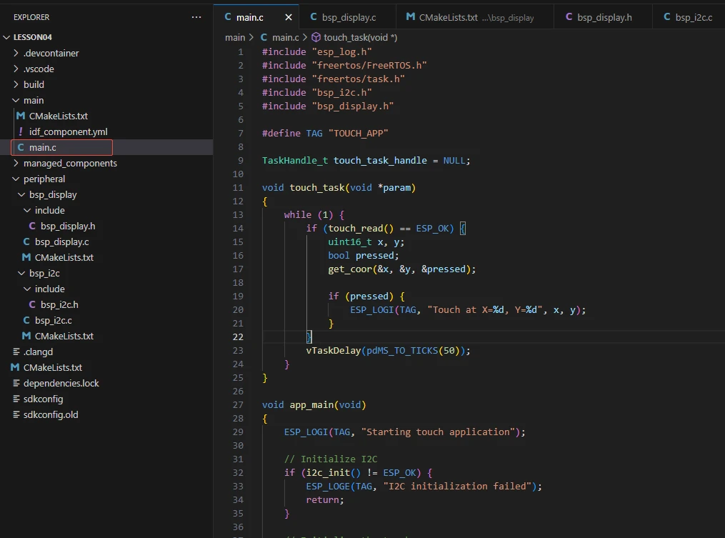
Let's first explain main.c.
esp_log.h: Provides the logging printing interface of ESP-IDF (such as ESP_LOGI, ESP_LOGE, etc.).
freertos/FreeRTOS.h and freertos/task.h: Functions and task management interfaces related to FreeRTOS.
"bsp_i2c.h": Custom I2C driver, initializes the I2C bus and reads/writes devices.
"bsp_display.h": Custom touchscreen driver interface, provides functions such as touch_init, touch_read, get_coor, etc.
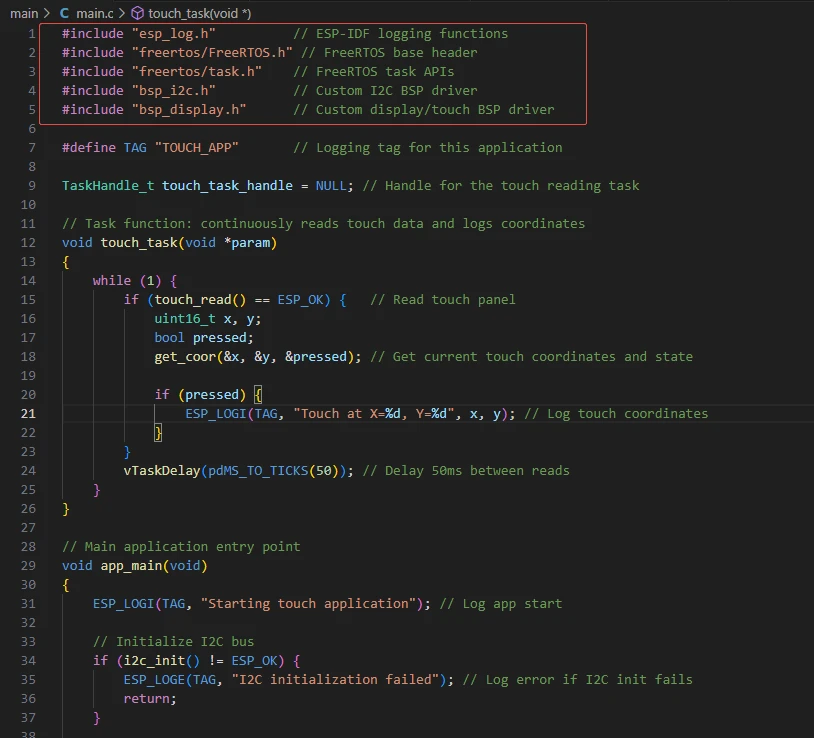
TAG: Log identifier, used to distinguish the source of the log.
touch_task_handle: FreeRTOS task handle, used to manage the touch reading task.

Infinite loop, reading touchscreen data every 50ms.
touch_read(): Read GT911 touchscreen data and update internal coordinates.
get_coor(&x, &y, &pressed): Obtain the current touch coordinates and pressing status.
If a touch is detected (pressed = true), print the touch coordinates.
vTaskDelay(pdMS_TO_TICKS(50)): Put the task to sleep for 50ms to avoid frequent polling occupying CPU.

Then comes the main function app_main.
It first prints the information about the program startup.
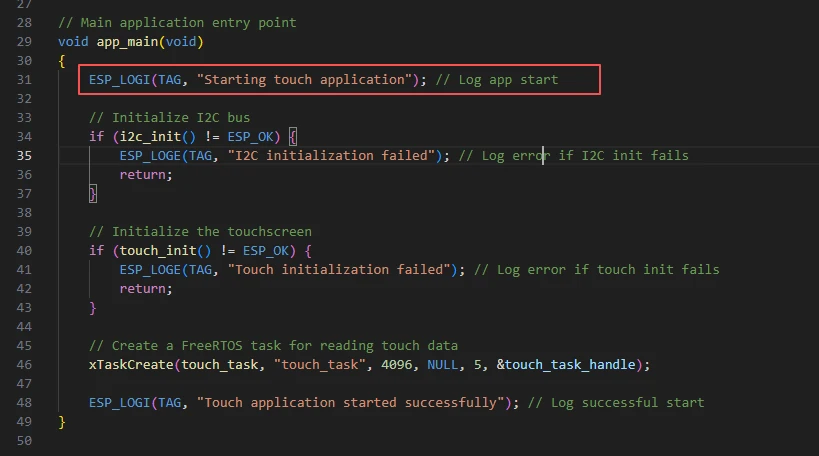
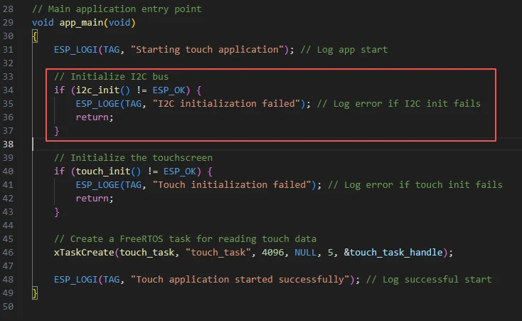
Call the initialization code in "bsp_i2c.c" to initialize the I2C bus, which is used for communication with the touch screen chip.
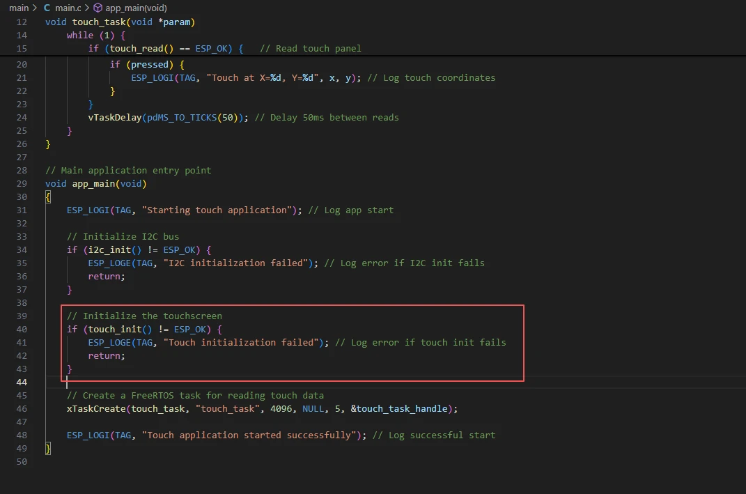
Call the initialization screen touch code in "bsp_display.c" to initialize the GT911 touch screen.
If it fails, print the error log and return.
The following code is also familiar to you. You have encountered it in previous courses. The function of this line of code is to create and start a task named "touch_task" in FreeRTOS, allowing it to periodically read touch screen data in an independent thread. At the same time, through the "touch_task_handle" handle, this task can be managed later.

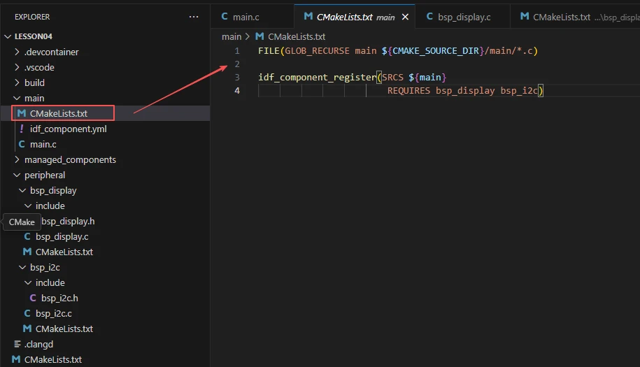
Now let's take a look at the "CMakeLists.txt" file in the "main" directory.
The function of this CMake configuration is as follows:
Collect all the .c source files in the "main/" directory as the source files for the component;
Register the main component with the ESP-IDF build system and declare that it depends on the custom component "bsp_display" and the custom component "bsp_i2c";
This way, during the build process, ESP-IDF knows to build "bsp_display" and "bsp_i2c" first, and then build "main".
Note: In the subsequent courses, we will not start from scratch to create a new "CMakeLists.txt" file. Instead, we will make some minor modifications to this existing file to integrate other drivers into the main function.
Complete Code
Kindly click the link below to view the full code implementation.
GitHub Link
Programming Steps
Now the code is ready. Next, we need to flash the ESP32-P4 so that we can observe the results.
First, we connect the Advance-P4 device to our computer host via the USB cable.
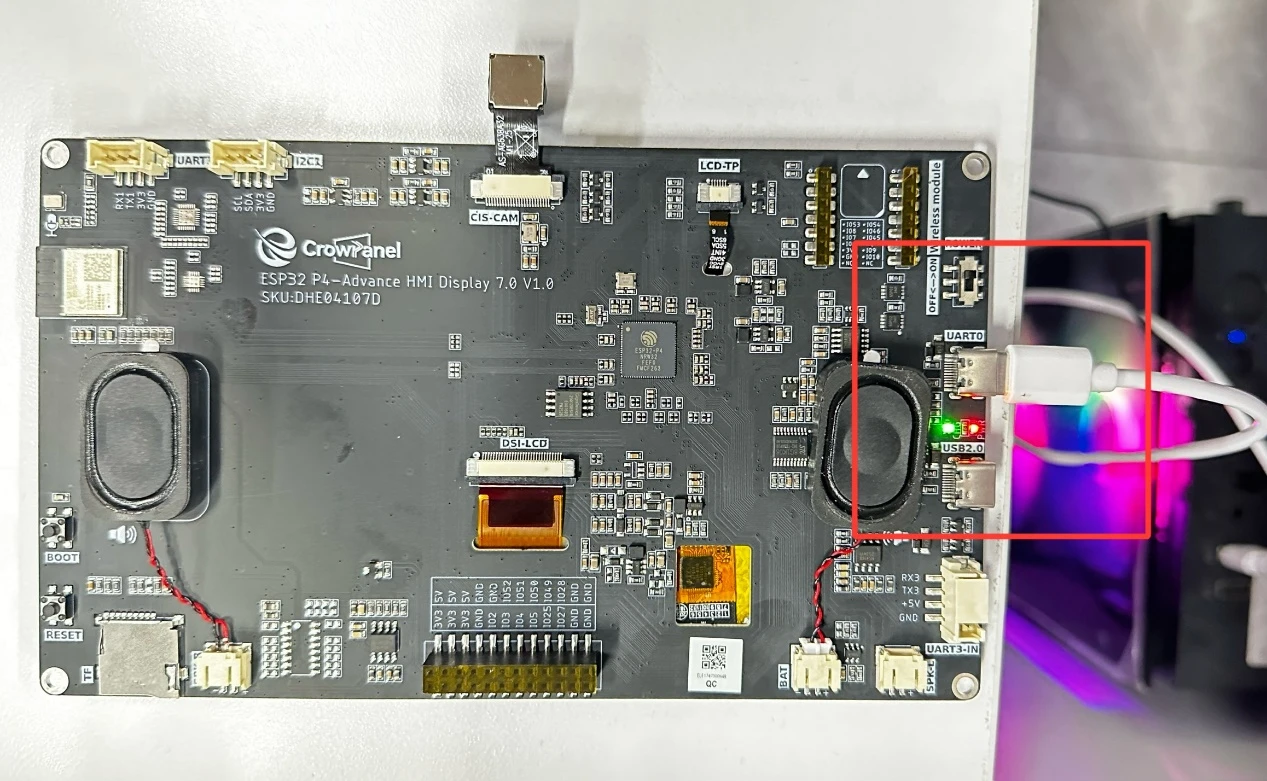
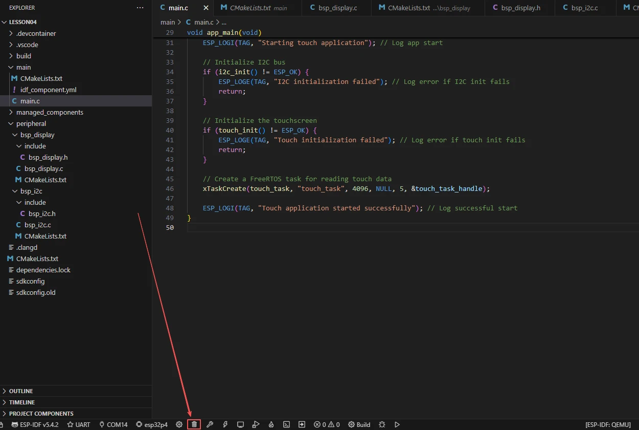
Before starting the burning process, delete all the compiled files and restore the project to its initial "uncompiled" state. (This ensures that the subsequent compilation will not be affected by your previous actions.)
Then, following the steps in the first section, select the ESP-IDF version, the code upload method, the serial port, and the chip to be used.
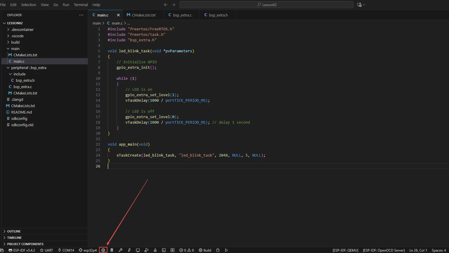
Then here we need to configure the SDK.
Click the icon in the picture below.
Wait for a moment for the loading process to complete, and then you can proceed with the related SDK configuration.
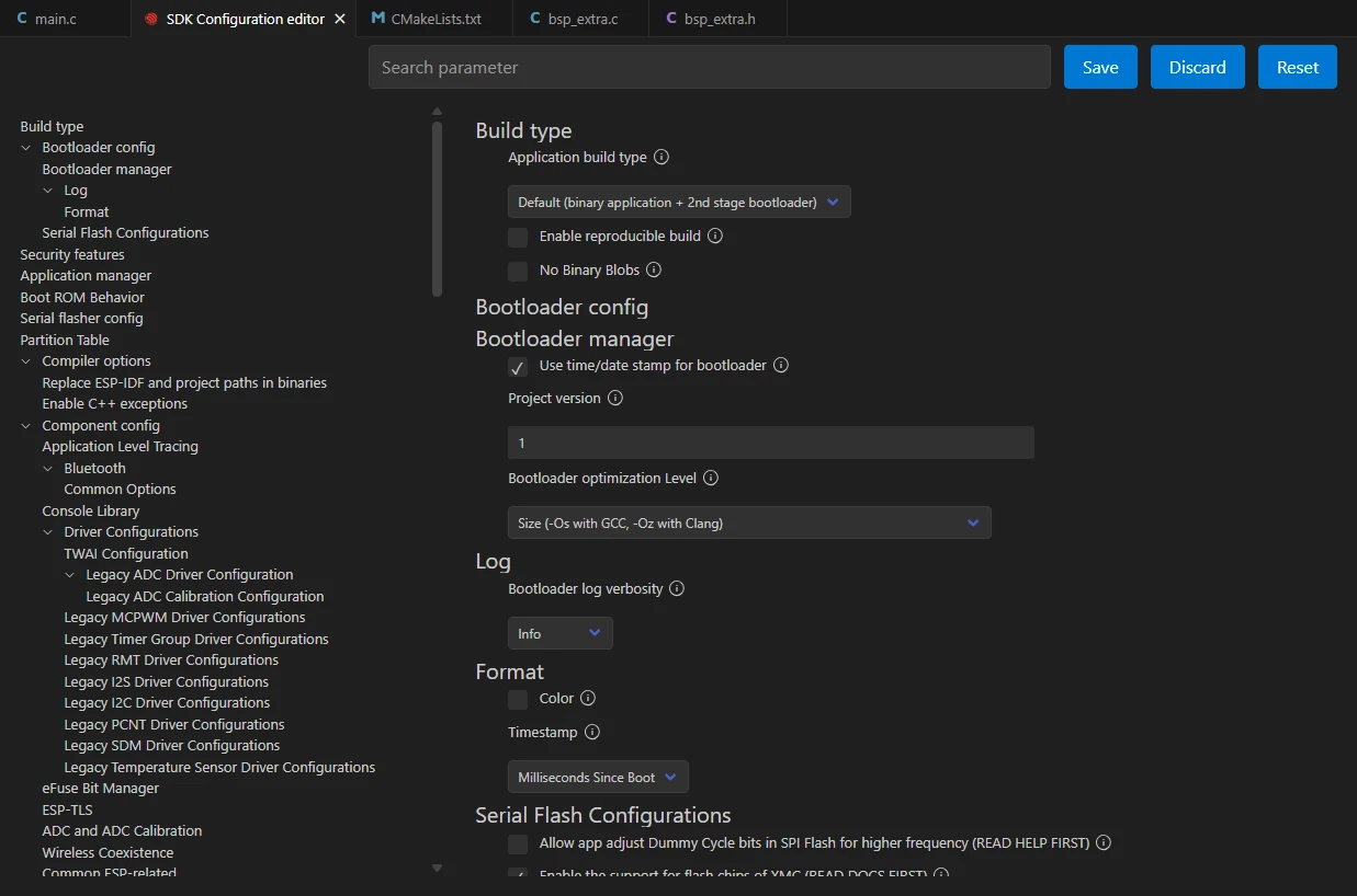
Then, search for "flash" in the search box.
(Make sure your flash settings are the same as mine.)
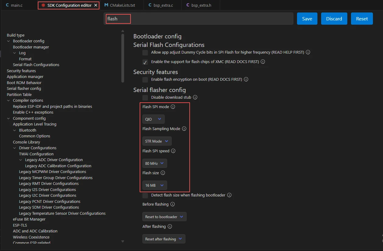
After the configuration is completed, be sure to save your settings.

Then we will compile and burn the code (as detailed in the first class).
Here, we would like to introduce to you another very convenient feature. With just one button press, you can perform the compilation, upload, and open the monitor at once. (This is provided that the entire code is error-free.)

After waiting for a while, the code compilation and upload process was completed, and the monitor also opened. By touching the Adcance-P4 screen, you will be able to see the coordinates of the screen you touched displayed.