Lesson07---Turn on the screen
Introduction
In this class, we will start by teaching you how to turn on the screen. Then, while turning on the screen backlight, we will display "Hellow Elecrow" on the screen. Of course, you can replace it with whatever you want.
The main focus of this class is to teach you how to turn on the screen backlight and turn on the screen, in preparation for the subsequent courses.
Hardware Used in This Lesson
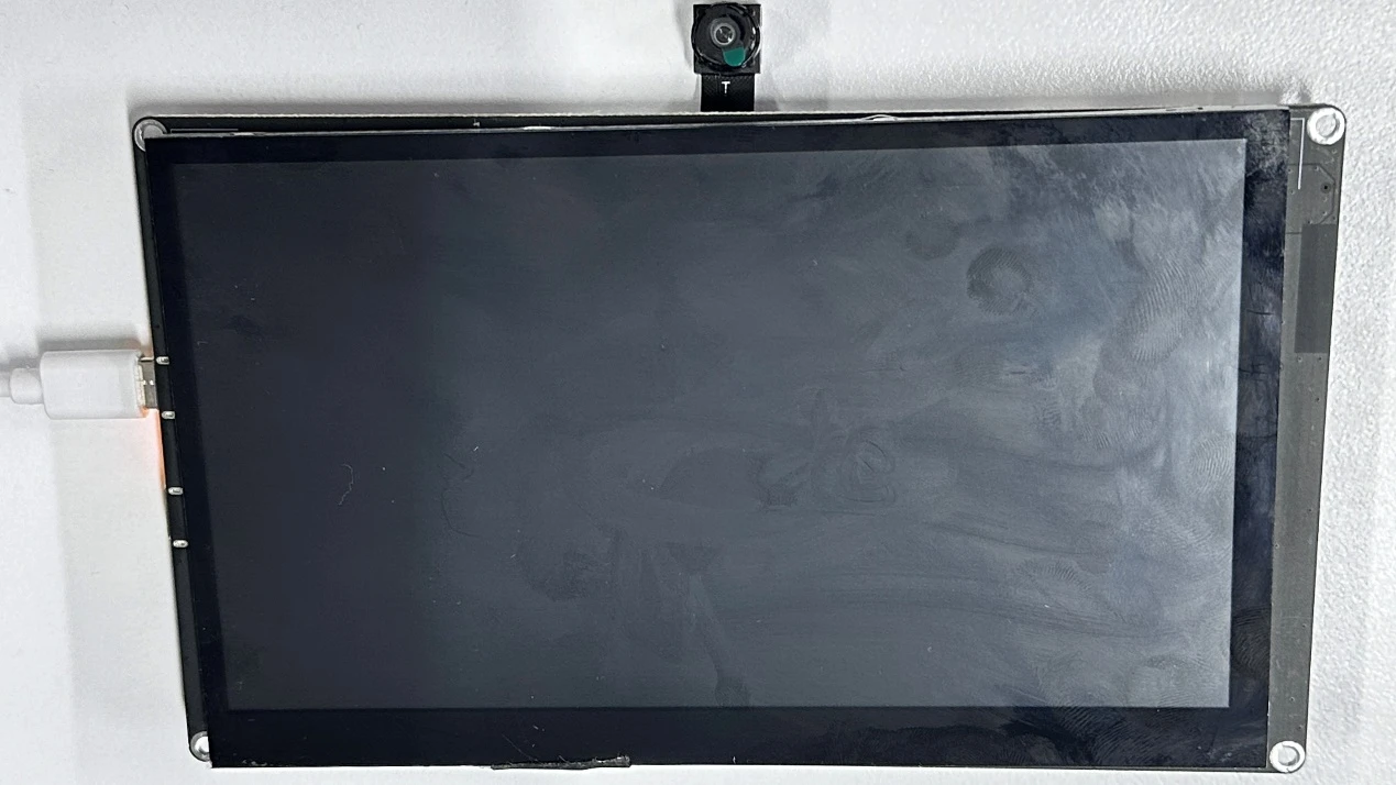
The screen on the Advance-P4
Display Screen CXM090IPS-D27 Schematic Diagram
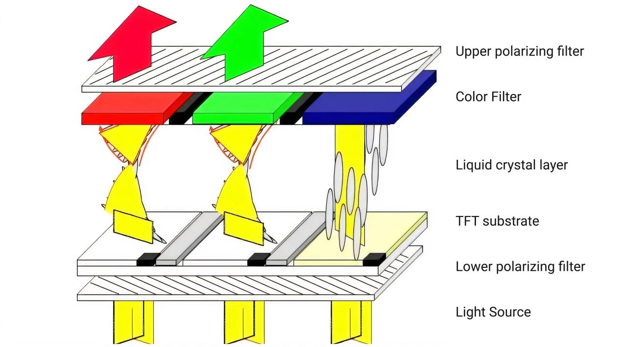
Firstly, the backlight (usually an LED array) emits a white surface light source, providing the basic light for display.
Then, the lower polarizer polarizes and filters the light from the backlight, allowing only light of a specific polarization direction (such as horizontal) to pass through, forming linearly polarized light. Next, the light reaches the TFT substrate, where the thin-film transistors (TFTs) on the substrate act as switching devices, controlling the electrical state of the liquid crystal molecules in the corresponding pixel area based on the applied voltage, thereby changing the alignment direction of the liquid crystal molecules.
Liquid crystal molecules have optical anisotropy and electric field response characteristics. The change in their alignment direction modulates the polarization state of the passing polarized light. Subsequently, the light enters the color filter, which is composed of red, green, and blue primary color filter units.
Only light corresponding to the color of the filter units (for example, only red light can pass through the red filter unit) can pass through, generating primary color light. Finally, the upper polarizer (whose polarization direction is perpendicular to that of the lower polarizer, such as horizontal for the lower polarizer and vertical for the upper polarizer) filters the light that has passed through the color filter again.
Only light with a polarization direction consistent with the allowed direction of the upper polarizer can pass through.
Through the precise control of the liquid crystal molecules in each pixel by the TFT substrate, the polarization state of the polarized light is adjusted. Combined with the color filtering of the color filter and the polarization selection of the upper and lower polarizers, different pixels present different brightness and colors, ultimately forming a visible color image.
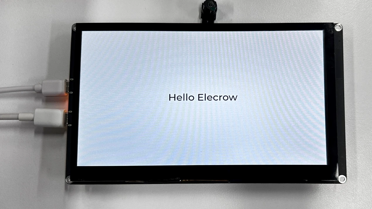
Operation Effect Diagram
After running the code, you will be able to visually see that "Hello Elecrow" is displayed on the screen of the Advance-P4.
Key Explanations
The main focus of this class is to turn on the screen for display. Here, we will provide everyone with a new component called bsp_illuminate. This component is mainly responsible for driving the screen, turning on the backlight, and performing related displays. As you know, you can call the interface we have written at the appropriate time.
Next, we will focus on understanding the bsp_illuminate component.
First, click on the Github link below to download the code for this lesson.
GitHub Link
Then, drag the code of this lesson into VS Code and open the project file.
After opening it, you can see the framework of this project.
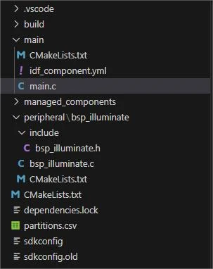
In the example of this class, a new folder named "bsp_illuminate" was created under the "peripheral" directory. Inside the "bsp_illuminate" folder, a new "include" folder and a "CMakeLists.txt" file were created.
The "bsp_illuminate" folder contains the "bsp_illuminate.c" driver file, and the "include" folder contains the "bsp_illuminate.h" header file.
The "CMakeLists.txt" file will integrate the driver into the build system, enabling the project to utilize the screen display functionality described in "bsp_illuminate.c".
Screen display code
The driver code displayed on the screen consists of two files: "bsp_illuminate.c" and "bsp_illuminate.h".
Next, we will first analyze the "bsp_illuminate.h" program.
"bsp_illuminate.h" is a header file for the screen display module, mainly used for:
Making the functions, macros, and variable declarations implemented in "bsp_illuminate.c" available for use by external programs.
Allowing other .c files to simply include "bsp_illuminate.h" to call this module.
In other words, it is the interface layer, exposing which functions and constants can be used externally while hiding the internal details of the module.
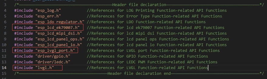
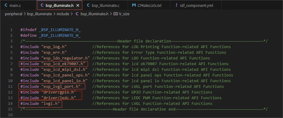
In this component, all the libraries we need to use are placed in the "bsp_illuminate.h" file for unified management.
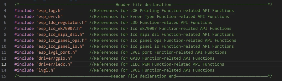
Such as esp_lcd_ek79007.h, esp_lvgl_port.h, and lvgl.h (these are libraries under the network component)
In this case, we need to fill in the versions of esp_lcd_ek79007, esp_lvgl_port and lvgl in the idf_component.yml file located in the main folder.
Since these are official libraries, we need to use the official libraries to achieve the screen display function on our Advance-P4.
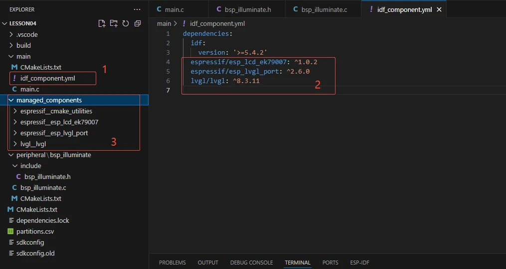
When the project is compiled in the future, it will automatically download the esp_lcd_ek79007 library version 1.0.2, the esp_lvgl_port version 2.6.0, and the lvgl version 8.3.11. After the download is completed, these network components will be saved in the managed_components folder. (This is automatically generated after filling in the version numbers.)
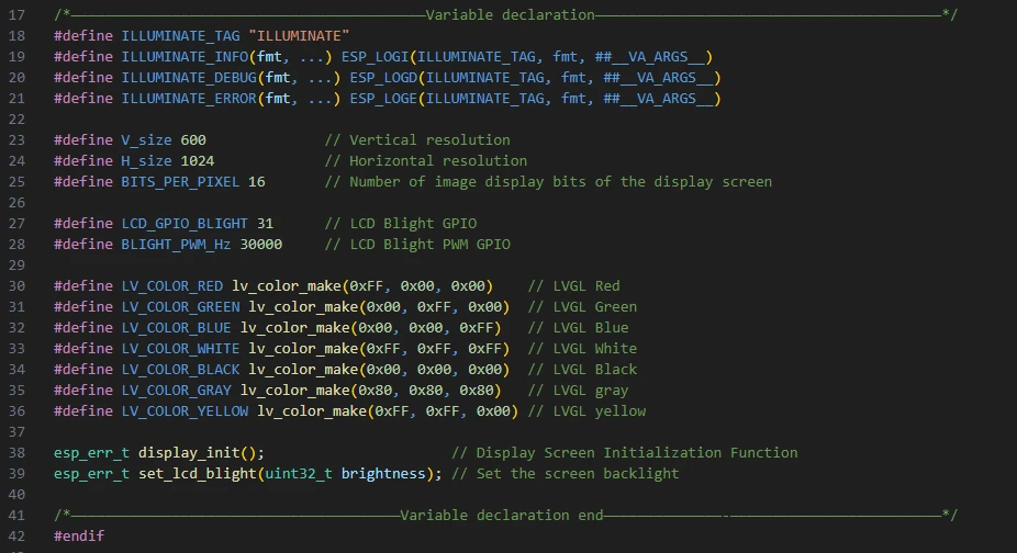
Then comes the declaration of the variables we need to use, as well as the declaration of the functions. The specific implementations of these functions are in "bsp_illuminate.c".
They are all uniformly placed in "bsp_illuminate.h" for ease of calling and management. (When used in "bsp_illuminate.c", we will understand their functions later.)
Let's take a look at "bsp_illuminate.c" again. We'll examine the specific functions of each one.
bsp_illuminate:
This component provides underlying driver support for the subsequent application layer (such as in app_main where it displays "Hello Elecrow"). It enables you to draw and display using the LVGL API without having to worry about the details of the hardware driver.
Then the following functions are the interfaces we call to implement the screen display.
blight_init / set_lcd_blight → Control the backlight.
display_port_init / display_port_deinit → Manage the display interface resources.
lvgl_init → Start the LVGL framework.
display_init → Provide the encapsulation of the overall display initialization process.
blight_init:
Initialize the LCD backlight. It will configure the specified backlight GPIO as output mode, and then configure the PWM signal through the LEDC timer + channel to lay the foundation for subsequent adjustment of the backlight brightness.
set_lcd_blight(uint32_t brightness) :
Set the LCD backlight brightness. Based on the incoming brightness value (0--100), calculate the corresponding PWM duty cycle, call the LEDC API to update the duty cycle, and achieve the brightness adjustment of the backlight; if it is 0, then completely turn off the backlight.
display_port_init(void) :
Initialize the display interface. It first configures and creates the MIPI DSI bus and DBI IO, then selects the color format according to the pixel depth, configures the DPI parameters (resolution, timing, etc.), and finally initializes the EK79007 controller panel through the vendor driver and completes the reset and startup.
display_port_deinit(void) :
Reinitialize the display interface. It releases the panel, IO, and DSI bus resources, clears the related handles, and closes the backlight to ensure that the resources will not be leaked.
lvgl_init() :
Initialize the LVGL graphics library. It creates the LVGL task, timer, and memory configuration, then registers the previously created LCD panel in LVGL as a display device, sets the buffer, resolution, color format, refresh mode, etc., and prepares for the subsequent drawing of the graphical interface.
display_init() :
The complete display initialization entry function.
It calls the backlight initialization → display interface initialization → LVGL initialization in sequence. If any step fails, it immediately returns an error. Finally, it defaults to setting the backlight brightness to 0 (turn off the backlight). This is the overall entry point when called externally.
That's all about the components of bsp_illuminate. Just remember how to call these interfaces and you'll be fine.
Then, if we need to make a call, we must also configure the "CMakeLists.txt" file located in the "bsp_illuminate" folder.
This file is placed in the "bsp_illuminate" folder and its main function is to inform the build system (CMake) of ESP-IDF: how to compile and register the "bsp_illuminate" component.

The reason why it is driver, esp_lcd_ek79007, lvgl, and esp_lvgl_port is that we called them in "bsp_illuminate.h" (for other libraries that are system libraries, there is no need to add them)
Main function
The main folder is the core directory for program execution, and it contains the executable file main.c for the main function.
Add the main folder to the "CMakeLists.txt" file of the build system.
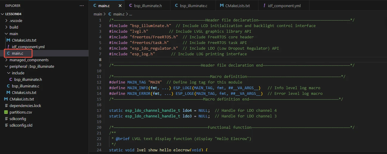
This is the entry file of the entire application. In ESP-IDF, there is no "int main()". Instead, the program starts running from the "void app_main(void)" function.
Let's first explain main.c.
On the ESP32-P4, it completes the acquisition of the power LDO → initialization of the screen driver → turning on the backlight → displaying the text "Hello Elecrow" in the center of the screen using LVGL.
"bsp_illuminate.h": This is a header file of the board support package (BSP), which encapsulates the initialization of LCD display screens and backlight control interfaces related to hardware, allowing the main program to directly call these functions without needing to concern about the underlying register operations.
"lvgl.h": This is the main header file of the LVGL graphics library, providing functions for creating and managing GUI objects, setting styles, layouts, and event handling, enabling you to display text, graphics, and animations on the screen.
"freertos/FreeRTOS.h": This is the core header file of FreeRTOS, defining the basic types, macros, and data structures of the operating system, providing underlying support for task scheduling, time management, and memory management.
"freertos/task.h": This is the header file of FreeRTOS task management, providing API for creating, deleting, suspending, and delaying tasks, enabling the program to achieve concurrent execution of multiple tasks.
"esp_ldo_regulator.h": This is the header file of the LDO (Low Dropout Linear Regulator) control interface provided by ESP-IDF, allowing the program to apply for, configure, and control LDO channels, providing stable voltages for peripherals such as LCD.
"esp_log.h": This is the header file of the log printing interface of ESP-IDF, providing log output of different levels (INFO, ERROR, etc.), enabling developers to debug and track the running status of the program.

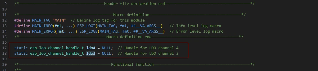
The following two lines of code define the control handles for LDO channels 3 and 4, which are used to bind to the actual LDO power channels during subsequent initialization, so that the program can control the output of different voltage power supplies.
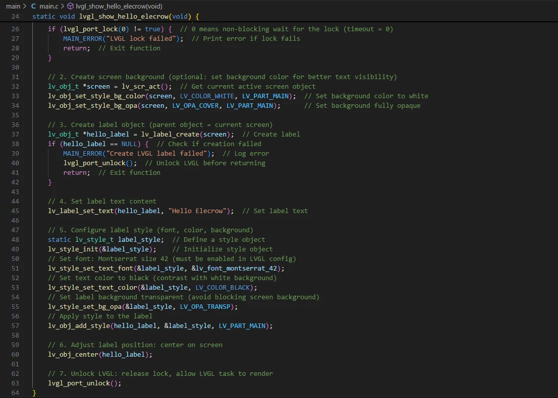
lvgl_show_hello_elecrow():
Function: Create a centered label on the current screen of LVGL and display the text "Hello Elecrow". Also, set the font size/color and other styles for the text. (If modifying the content, replace "Hello Elecrow") Key points:
First, call lvgl_port_lock(0) to attempt to acquire the LVGL mutex lock (0 indicates non-blocking immediate return), to prevent concurrent modification of LVGL objects. If the lock acquisition fails, the function simply returns and prints an error - this might not display the text because other tasks may hold the lock.
Use lv_scr_act() to obtain the current screen object and set the background to white (LV_PART_MAIN).
Create a label, set the text, initialize the static lv_style_t label_style and set the font (lv_font_montserrat_42), color to black, background transparent, and then add the style to the label.
Finally, call lv_obj_center() to center the label, release the LVGL lock lvgl_port_unlock() to allow the LVGL rendering task to continue working.
(The font lv_font_montserrat_42 must be enabled and linked to the project during LVGL build, otherwise there will be compilation/linking or runtime issues.)
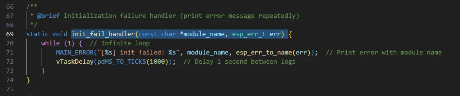
init_fail_handler(const char *module_name, esp_err_t err):
Function: When the initialization of a certain module fails, this function will enter an infinite loop and print the error message (including the module name and error code string) once per second.
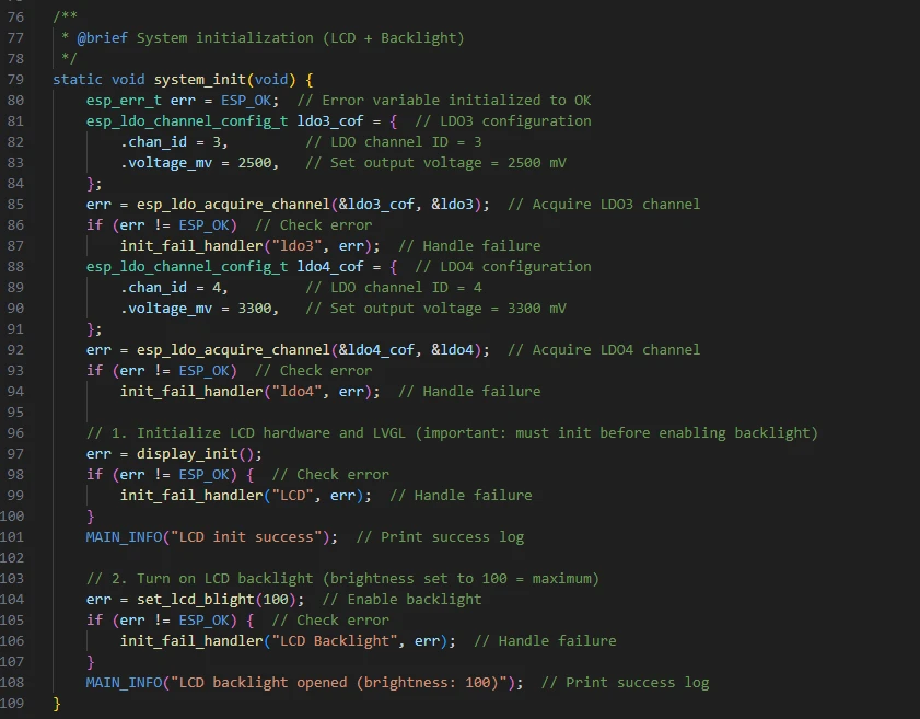
system_init(void):
Function: System-level initialization. First, it acquires two LDO channels (ldo3/ldo4), then calls display_init() to initialize the display system, and finally turns on the backlight to the maximum brightness (set_lcd_blight(100)). Key points:
First, construct esp_ldo_channel_config_t (setting chan_id = 3 and 4 with voltage 2500/3300 mV), and use esp_ldo_acquire_channel() to obtain the channel handle. If it fails, call init_fail_handler() to shut down and print the error message.
display_init() is implemented elsewhere (our "bsp_illuminate.c"), which is responsible for the complete initialization of the display link including backlight GPIO, MIPI DSI, LVGL registration, etc.
After success, set the backlight brightness to 100 (maximum), and print the success message.
Note:
esp_ldo_acquire_channel() requires LDO driver and hardware support. If the current board/chip does not have the corresponding LDO, it will return an error. (To light up the screen, these two channels must be enabled.)
Any step in display_init() that fails will be captured by init_fail_handler() and shut down to print the error message.
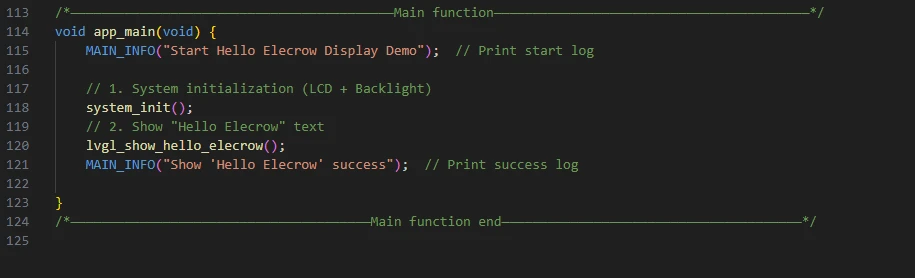
Then comes the main function app_main.
Function: Program entry point. It prints the start information, calls system_init() to complete the initialization of hardware and display, then calls lvgl_show_hello_elecrow() to draw the text, and finally prints the success message. Key points:
The function system_init() is blocking and critical: if it fails, it will enter an infinite loop in the init_fail_handler() and the app_main will not proceed.
The function lvgl_show_hello_elecrow() simply returns after creating the LVGL object; the actual image is refreshed to the screen by LVGL's own rendering task or tick (depending on the implementation of lvgl_port).
Now let's take a look at the "CMakeLists.txt" file in the "main" directory.
The function of this CMake configuration is as follows:
Collect all the .c source files in the "main/" directory as the source files for the component;
Register the "main" component with the ESP-IDF build system and declare that it depends on the custom component "bsp_illuminate".
This way, during the build process, ESP-IDF knows to build "bsp_illuminate" first, and then build "main".

Note: In the subsequent courses, we will not start from scratch to create a new "CMakeLists.txt" file. Instead, we will make some minor modifications to this existing file to integrate other drivers into the main function.
Complete Code
Kindly click the link below to view the full code implementation.
GitHub Link
Programming Steps
Now the code is ready. Next, we need to flash the ESP32-P4 so that we can observe the results.
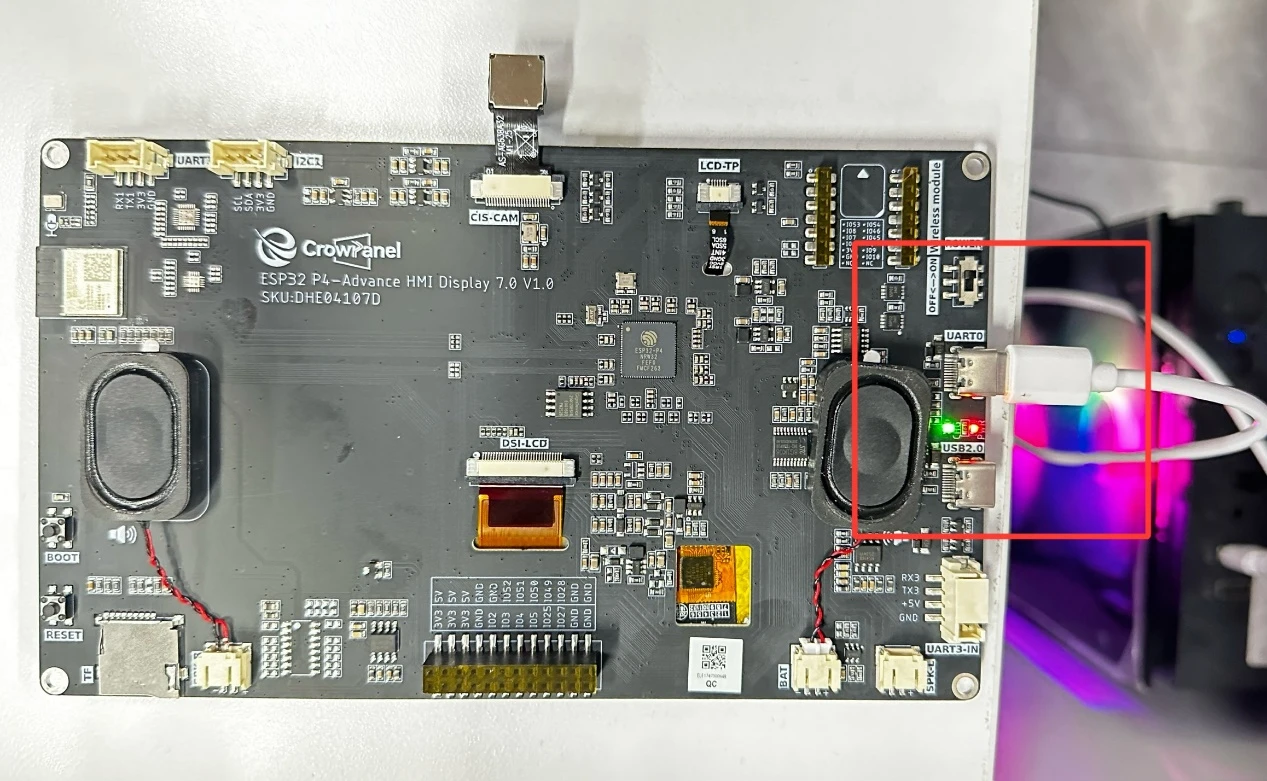
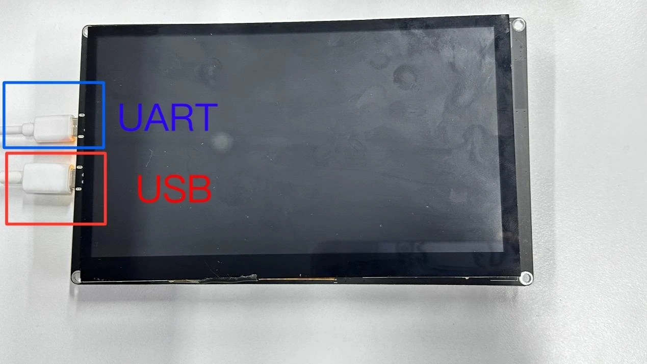
First, we connect the Advance-P4 device to our computer host via the USB cable.
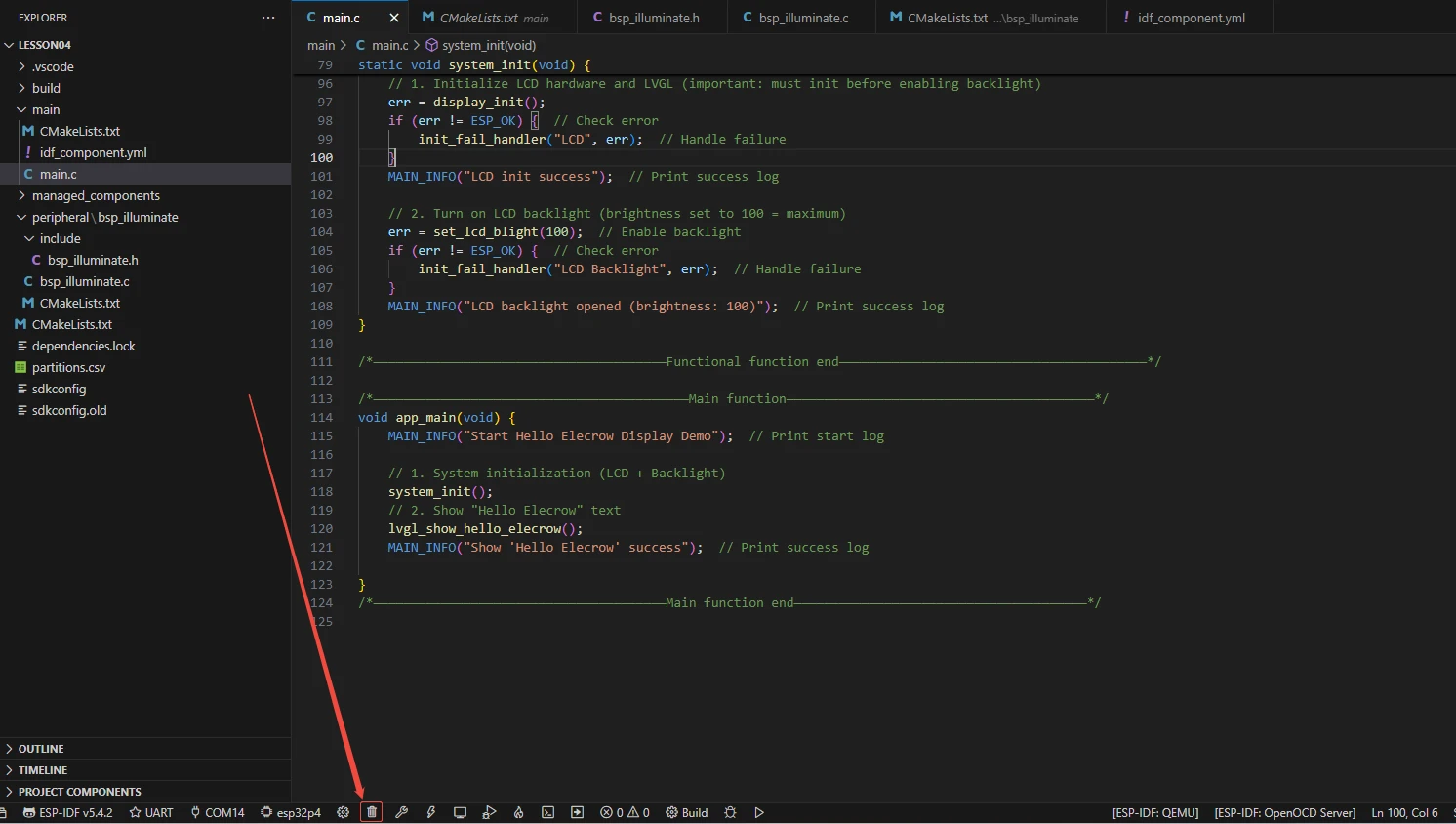
Before starting the burning process, delete all the compiled files and restore the project to its initial "uncompiled" state. (This ensures that the subsequent compilation will not be affected by your previous actions.)
Here, following the steps in the first section, first select the ESP-IDF version, the code upload method, the serial port, and the chip to be used.
Then here we need to configure the SDK.
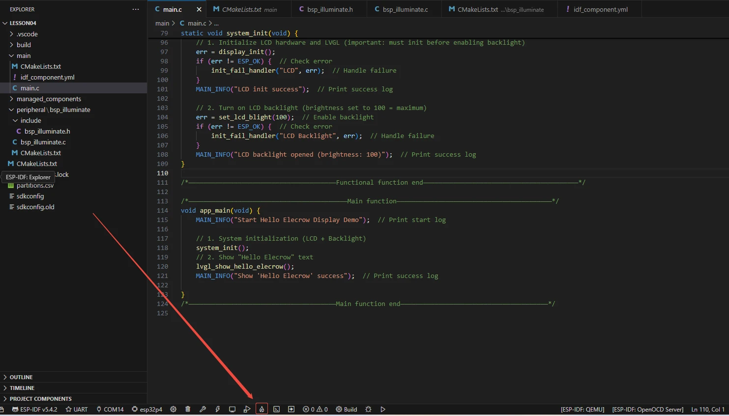
Click the icon in the picture below.
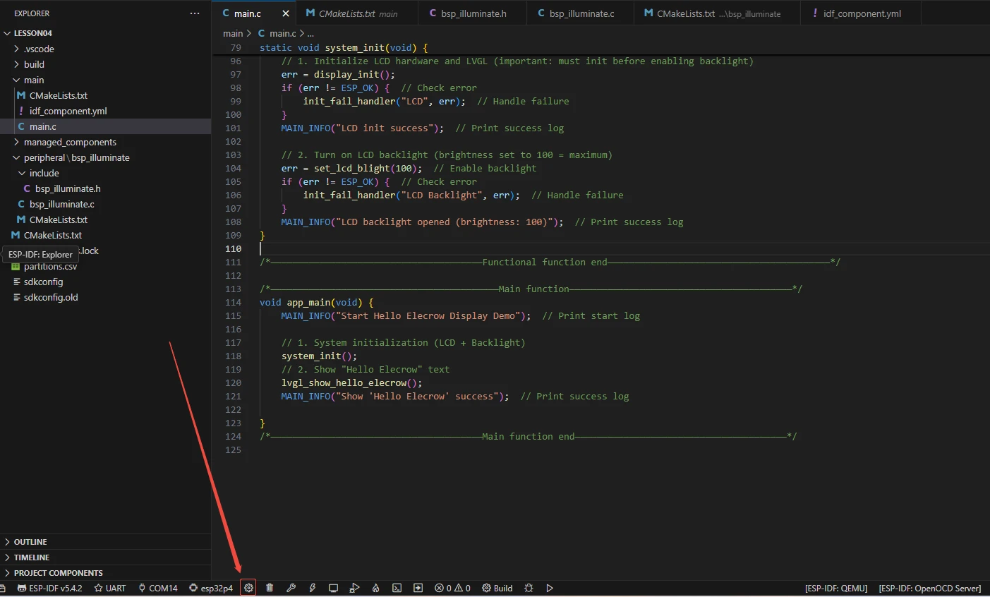
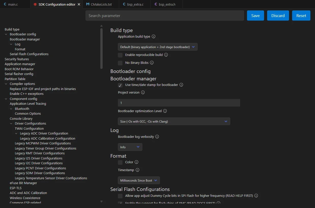
Wait for a moment for the loading process to complete, and then you can proceed with the related SDK configuration.
Then, search for "flash" in the search box.
(Make sure your flash settings are the same as mine.)
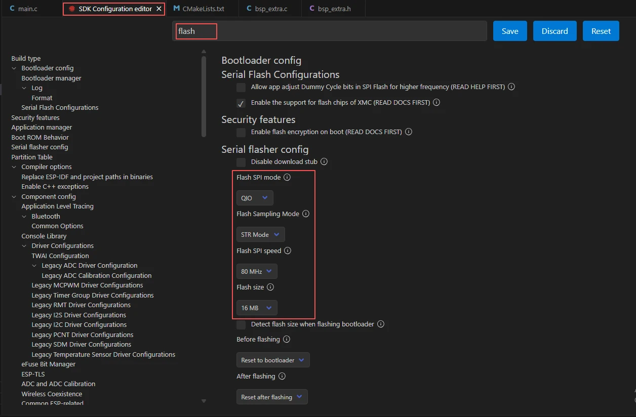
After the configuration is completed, remember to save your settings.
Then we will compile and burn the code (as detailed in the first class).
Here, we would like to introduce to you a very convenient feature. With just one button press, you can perform the compilation, upload, and open the monitor at once. (This is provided that the entire code is error-free.)
After waiting for a while, the code compilation and upload were completed, and the monitor also opened.
At this point, please remember to use another Type-C cable to connect your Advance-P4 through the USB2.0 interface. This interface provides a maximum current of about 500mA from the computer's USB-A port. When the Advance-P4 is using more external devices, especially the screen, it requires a sufficient current source. (It is recommended to use a charger for connection.)
After the burning process is completed.
You will be able to see that your Advance-P4 screen lights up, and the message "Hello Elecrow" appears in the center of the screen.