Lesson09--- LVGL Lighting Control
Introduction
In previous courses, we separately lit an LED, implemented touch testing, and lit up the screen.In this lesson, we will use LVGL to create two buttons to control the LED connected to the UART1 interface for turning on and off operations.
Pressing the ON button can turn on the LED, and pressing the OFF button can turn off the LED.
Hardware Used in This Lesson
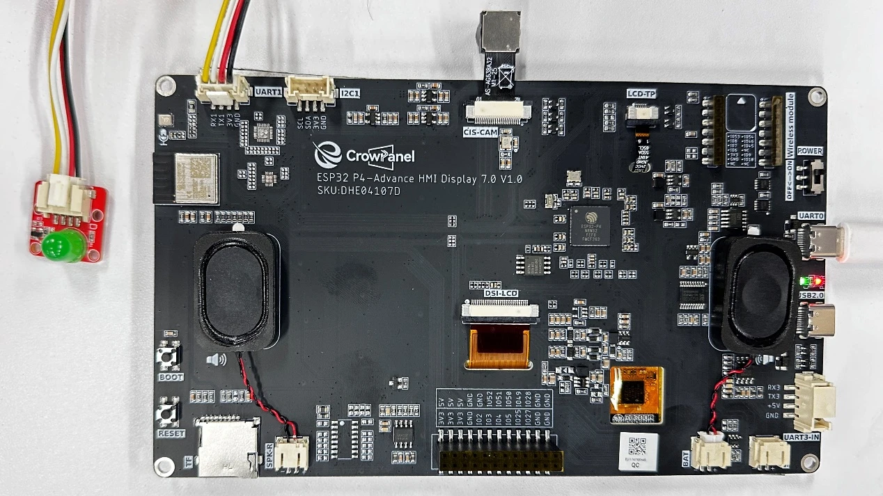
The UART1 interface on the Advance-P4 is connected to an LED.
Operation Effect Diagram
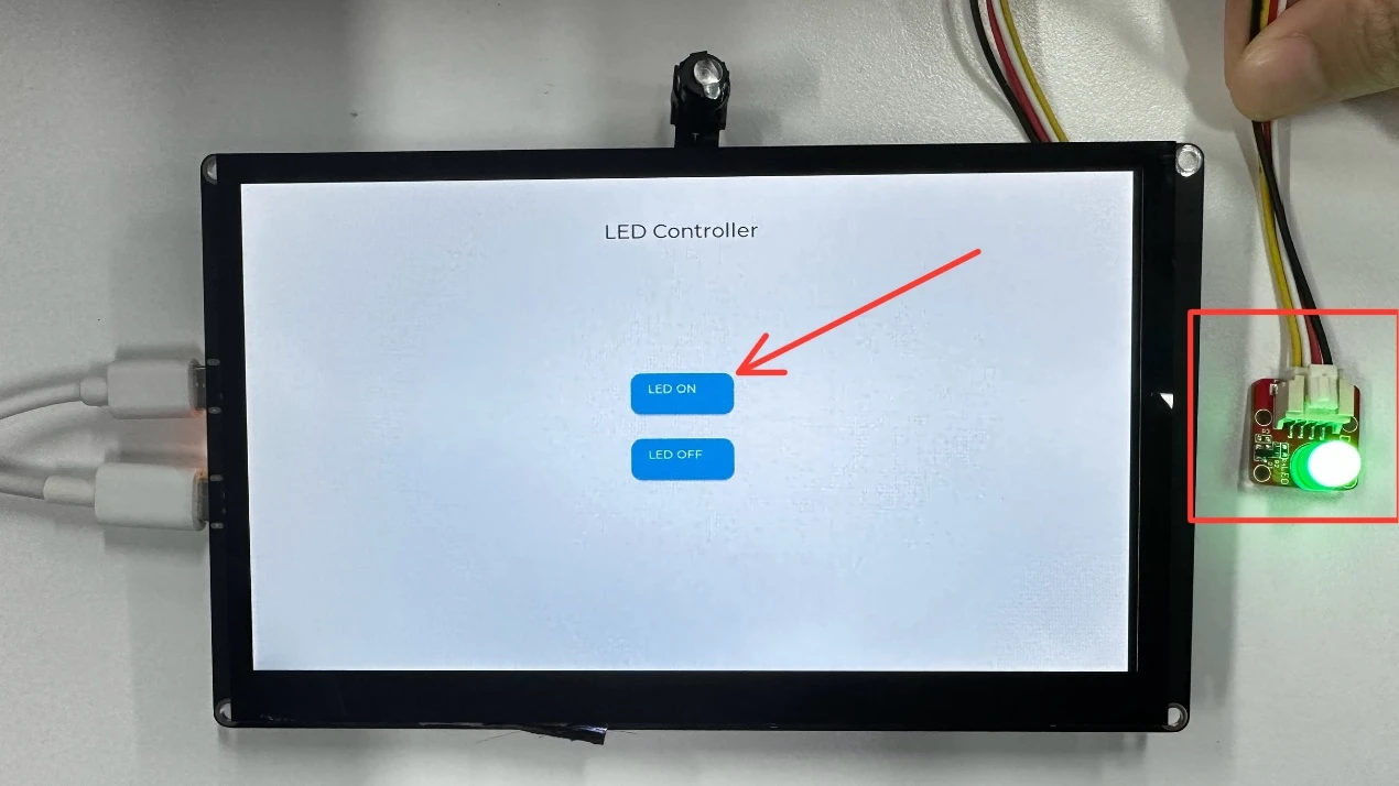
After running the code, when you press the "LED ON" button on the Advance-P4, you will be able to turn on the LED; when you press the "LED OFF" button, you will be able to turn off the LED.

Key Explanations
Now, the focus of this lesson is on how to use LVGL to create button objects and display the LVGL interface on the screen to achieve interactive effects.
First, click the GitHub link below to download the code for this lesson.
GitHub Link
Then drag the code for this lesson into VS Code and open the project file.
Once opened, you can see the framework of this project.

It can be seen that the components we use in this lesson are all those explained in previous sessions:
-
bsp_display: Touch-related driver.
-
bsp_i2c: Provides I2C driver support required for touch functionality.
-
bsp_extra: Used to control the LED connected to the UART1 interface.
-
bsp_illuminate: Responsible for screen initialization, screen lighting, and LVGL initialization.
LVGL Initialization Code
The components used in this lesson have been explained in detail in previous courses.
Here, we will only describe the LVGL initialization in detail.
lvgl_init() is the core initialization function of the entire graphic display system.
It mainly completes the following tasks:
-
Initializes the LVGL operating task environment (task/timer)
-
Registers and binds the display driver (Display) with LVGL's rendering layer
-
Registers and binds the touch input driver (Touch) to the LVGL input system
The purpose of doing this is to ensure that LVGL's graphic rendering, screen refreshing, and touch event handling are correctly linked with the underlying hardware.
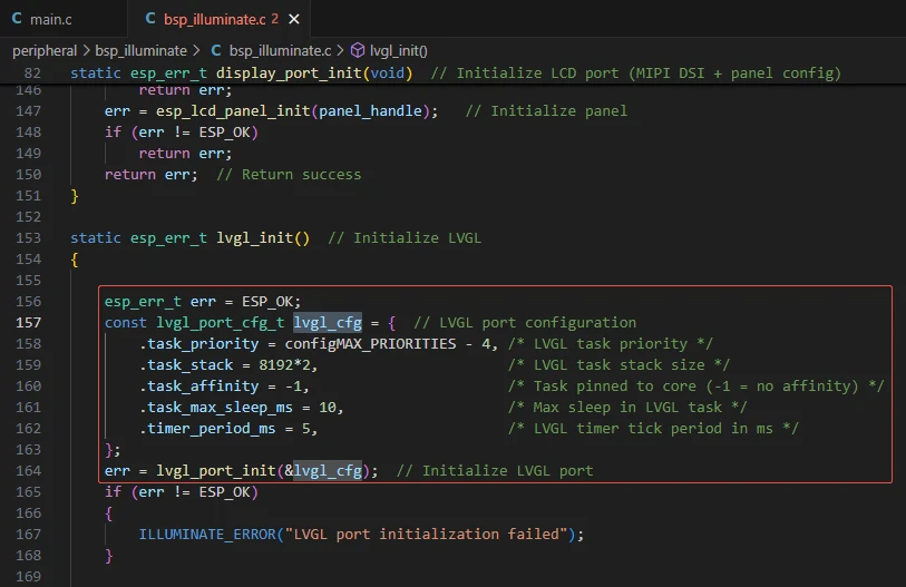
This part starts the LVGL task and timer through lvgl_port_init(), completing the following:
-
Allocating stack space for the LVGL main task (LVGL task);
-
Setting the task priority;
-
Configuring LVGL's periodic refresh timer;
-
Defining the maximum sleep time (i.e., the time the LVGL main loop sleeps when idle);
Significance:
The LVGL task continuously calls lv_timer_handler() to refresh the UI, process animations, and respond to events.
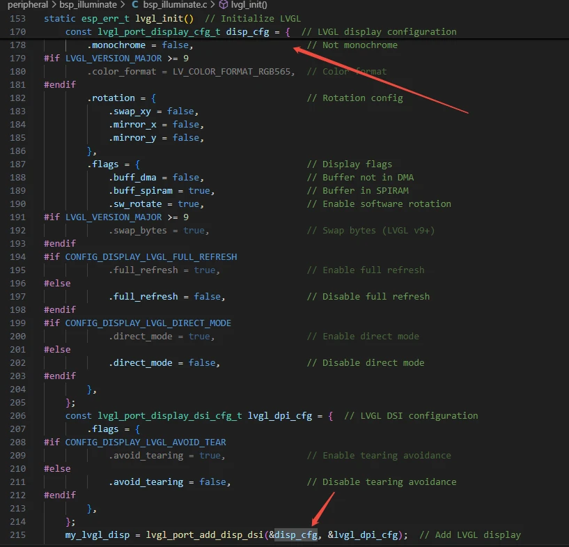
This step registers the display screen with LVGL through lvgl_port_add_disp_dsi(), serving as a bridge between "LVGL" and the "screen".
The initialization content includes:
-
io_handle: The physical communication interface of the screen (such as "MIPI", "SPI", "RGB", etc.)
-
panel_handle: Screen panel driver handle
-
buffer_size: Frame buffer size (used for rendering images)
-
double_buffer: Whether to use double buffering (prevents tearing and improves refresh smoothness)
-
hres/vres: Screen resolution
-
color_format: Color format (e.g., "RGB565")
-
rotation: Screen rotation/mirror configuration
-
flags:
-
buff_dma, buff_spiram: Whether the buffer is placed in internal memory or external "PSRAM"
-
full_refresh: Whether to enable full-frame refresh mode
-
direct_mode: Whether to directly output LVGL rendering results to the screen (reducing intermediate layers)
Significance:
All LVGL drawing operations will ultimately be updated to your screen through this display interface.
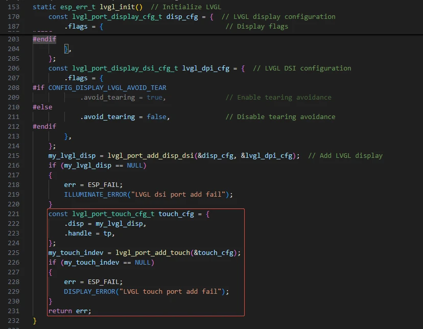
Register the touch input device with LVGL so that it can receive finger touch events.
The initialization content includes:
-
disp: The bound display object (the touch area corresponds to the screen)
-
handle: Touch driver handle (such as "FT5x06", "GT911", "CST816", etc.)
Significance:
Only in this way can LVGL's internal event system (such as button clicks, swipes) obtain touch coordinate data. After this part of the initialization, clicking buttons on the screen will produce visible effects.
This concludes our explanation of the components.
Main Function
The main folder is the core directory for program execution, which contains the main function executable file main.c.
Add the main folder to the "CMakeLists.txt" file of the build system.
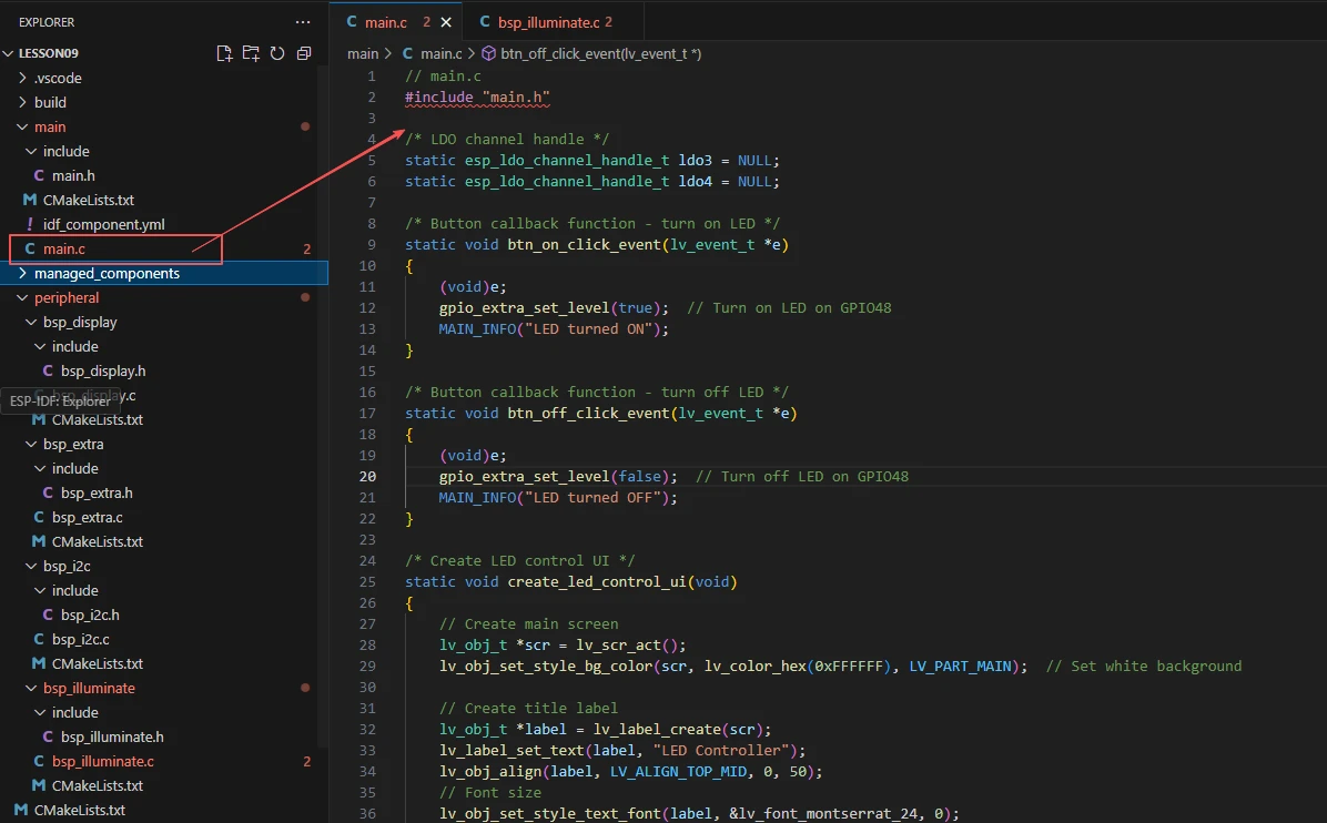
This is the entry file of the entire application. In ESP-IDF, there is no int main(), and execution starts from void app_main(void).
Let's first explain main.c to see how the interfaces in these four components are called to achieve the LVGL lighting effect. It creates a simple interface on the touch screen, containing two buttons labeled "LED ON" and "LED OFF" to control the LED on GPIO48.


Function:
"LDO" (Low Dropout Regulator) is a low dropout regulator used to supply power to devices such as screens and touch chips.
Two channels are enabled here:
"LDO3" outputs 2.5V (to power the screen)
"LDO4" outputs 3.3V (to power logic circuits or other peripherals)
After successful initialization:
Provides stable power for subsequent LCD and touch modules.
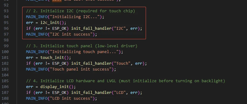
Initialize the "I2C" bus for communication with the touch chip.
The touch input part of LVGL usually needs to read coordinates via I2C.
After successful initialization:
The system can obtain touch event coordinate data through I2C.

Function:
Initialize the touch driver and register touch interrupts or polling read mechanisms.
Enable LVGL to receive touch events (clicks, swipes, etc.).
After successful initialization:
User clicks on the screen can trigger LVGL events.
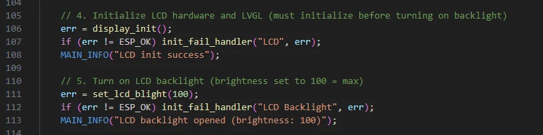
Function:
"display_init()": Initialize the LCD hardware interface and initialize the LVGL library;
"set_lcd_blight(100)": Turn on the screen backlight brightness (100 indicates maximum brightness).
After successful initialization:
The LVGL graphics system starts running, and the screen can display UI elements.
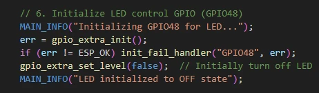
Function:
Configure "GPIO48" as an output pin;
Control the LED switch through "gpio_extra_set_level(true/false)".
After successful initialization:
The system can turn the LED on or off through button clicks.

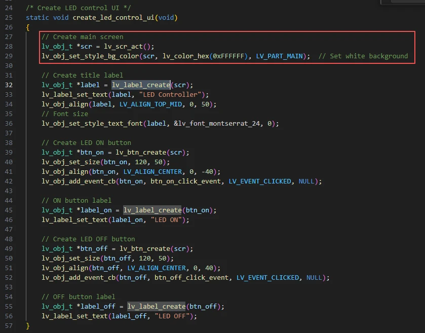
Function:
Create a concise interface using LVGL:
-
Background: white;
-
Title: "LED Controller";
-
Two buttons:
-
"LED ON": Triggers btn_on_click_event() to turn on the LED;
-
"LED OFF": Triggers btn_off_click_event() to turn off the LED.
Now let's take a look inside this function.

lv_scr_act()
Obtains the currently active screen object (LVGL has only one main screen by default).
You can understand it as "I want to place things on the current screen".
lv_obj_set_style_bg_color()
Sets the background color of this screen to white (0xFFFFFF).
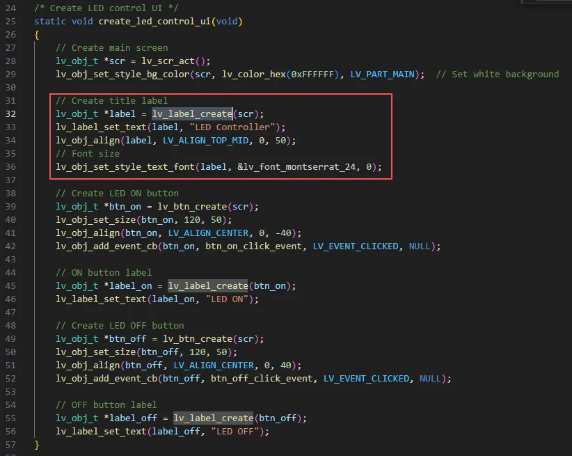
This section creates and configures a title text:
'lv_label_create(scr)': Creates a text label object on the main screen.
'lv_label_set_text()': Sets the text content to "LED Controller".
'lv_obj_align()': Sets the alignment to top-center, with a downward offset of 50 pixels.
'lv_obj_set_style_text_font()': Sets the font size to 24pt.
Result: A large-sized title "LED Controller" is displayed centered at the top of the screen.
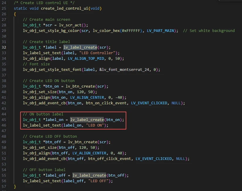
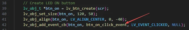
'lv_btn_create(scr)': Creates a button object and places it on the main screen.
'lv_obj_set_size()': Sets the button size to 120×50 pixels.
'lv_obj_align()': Aligns the button to the center, with an upward offset of 40 pixels.
'lv_obj_add_event_cb()': Binds a button event---when the button is "clicked", it calls the 'btn_on_click_event()' function.
Within this function, 'gpio_extra_set_level(true);' is executed → turning on the LED.
Result: A button is created slightly above the center of the screen, used for "turning on the light".

This label is a child object of the button (created within the button).
Its text will be automatically displayed in the center of the button.
Result: The text "LED ON" is displayed on the button.
The "OFF" button is created using the same logic.
Now let's look at the events bound to these two buttons after they are clicked.
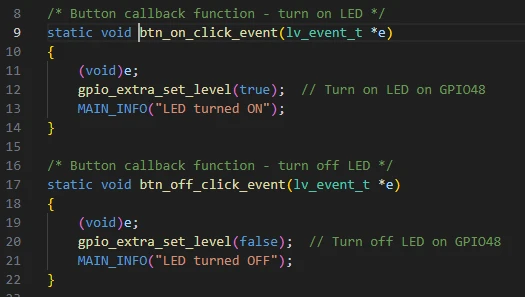
Here are the event handlers triggered when the buttons are clicked, which turn the LED on or off with immediate response.
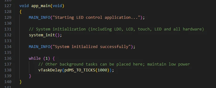
Next is the main function app_main:
Role: Serves as the program entry point, prints startup logs;
Calls system_init() to complete all initializations;
Enters a loop to keep the program running (LVGL's own tasks execute in the background).
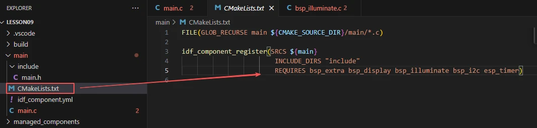
Finally, let's understand the "CMakeLists.txt" file in the main directory.
The role of this CMake configuration is:
Collects all .c source files in the main/ directory as the component's source files;
Registers the "main" component with the ESP-IDF build system and declares that it depends on "bsp_extra", "bsp_display", "bsp_illuminate", "bsp_i2c", and "esp_timer".
This way, during the build process, ESP-IDF knows to build these five components first, then build the "main" component.
Meanwhile, the header file references in main.h are also kept in sync.

Note:
In subsequent courses, we will not create a new "CMakeLists.txt" file from scratch. Instead, we will make minor modifications to this existing file to integrate other drivers into the main function.
Complete Code
Kindly click the link below to view the full code implementation.
GitHub Link
Programming Steps
Now the code is ready. Next, we need to flash it to the ESP32-P4 to see the actual effect.
First, connect the Advance-P4 device to our computer via a USB cable.
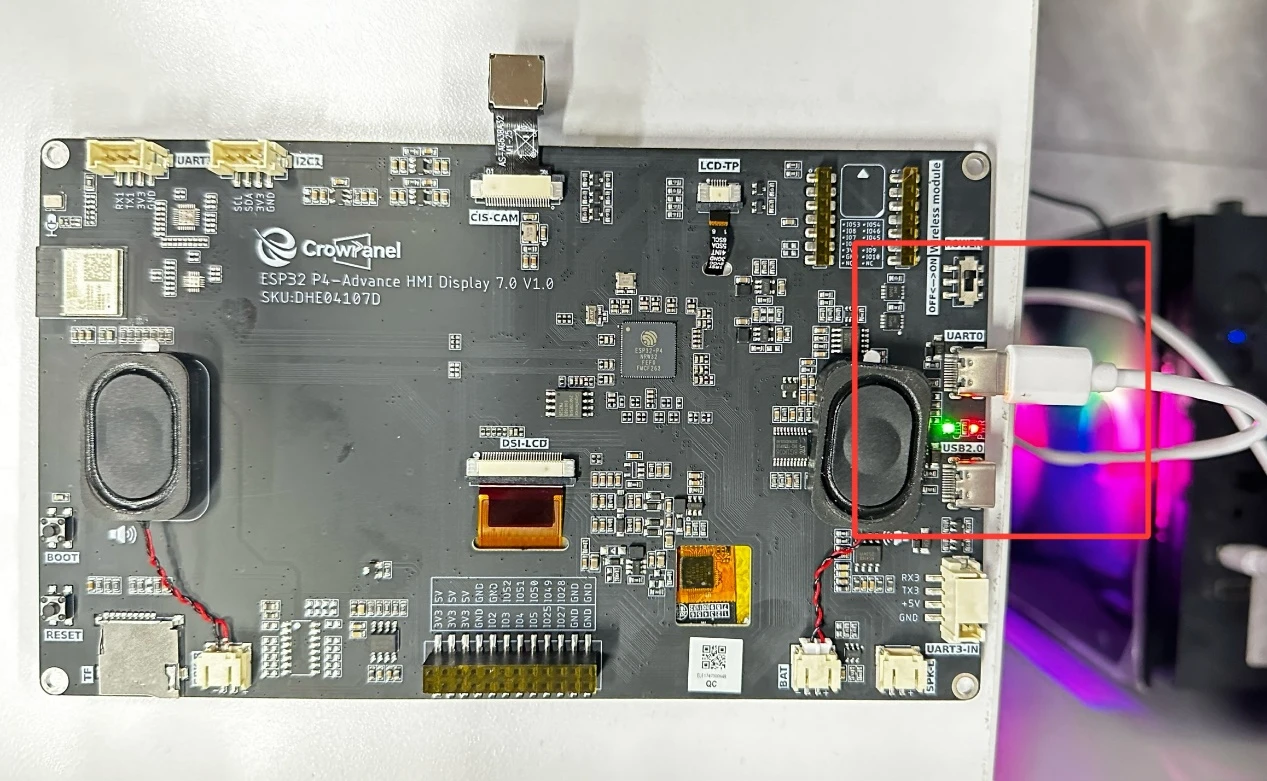
Also, remember to connect an LED to the UART1 interface.
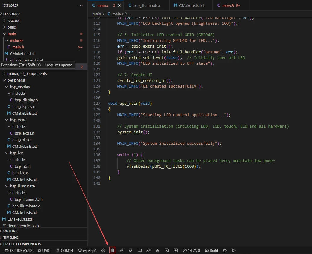
Before starting the flashing preparation, delete all compiled files to restore the project to its initial "unbuilt" state. (This ensures that subsequent compilations are not affected by your previous operations.)
Here, follow the steps from the first lesson to first select the ESP-IDF version, code upload method, serial port number, and the target chip (ESP32-P4).
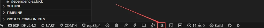
Next, we need to configure the SDK.
Click on the icon shown in the figure below.
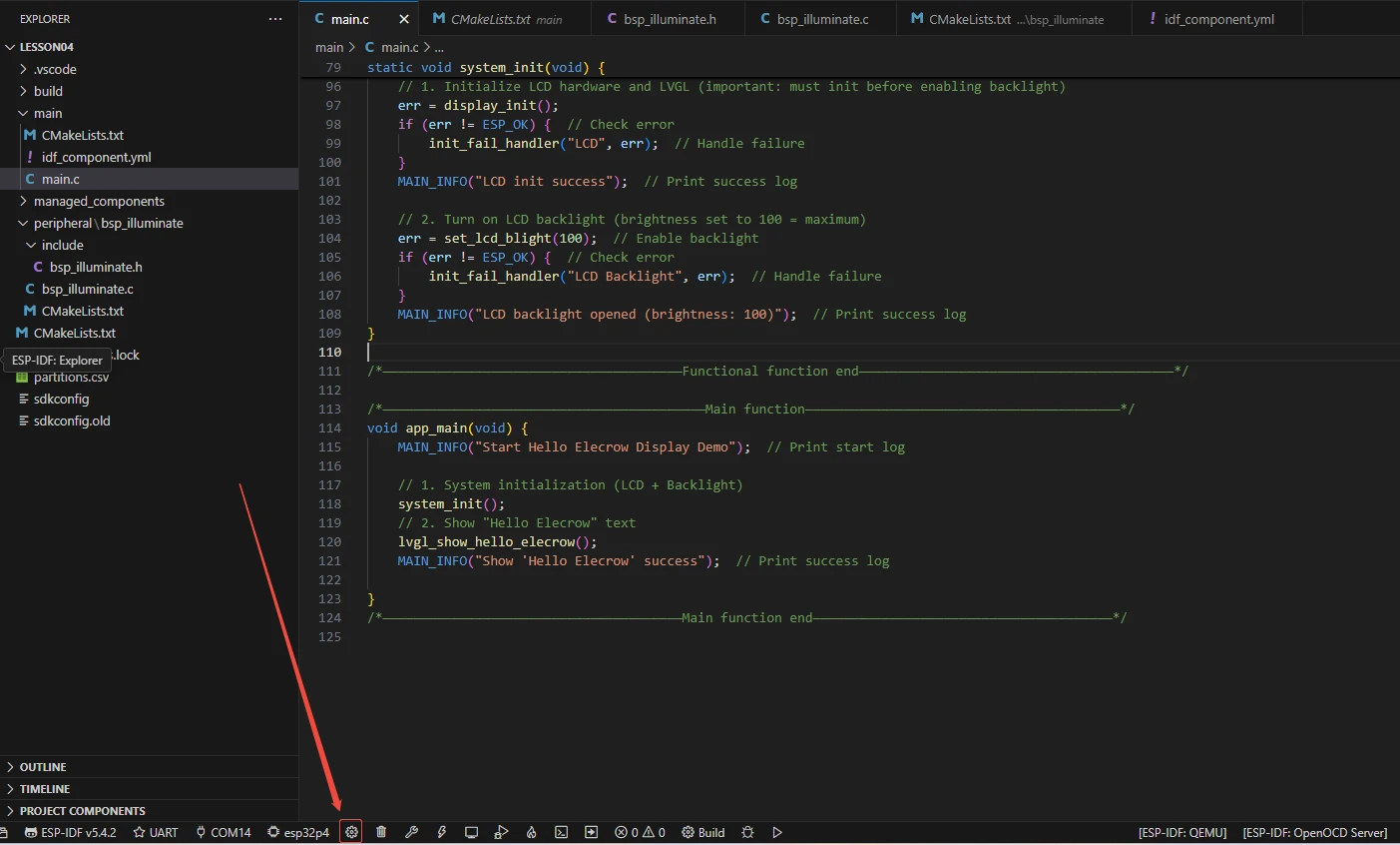
Wait for a moment while the configuration loads, and then you can proceed with the relevant SDK configuration.
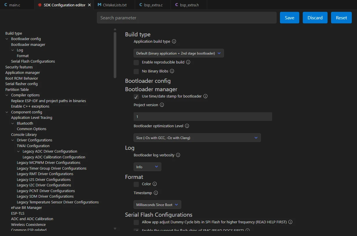
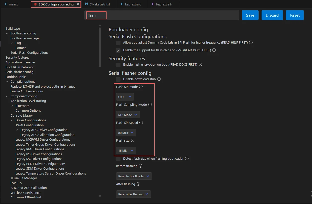
Then, search for "flash" in the search box.
(Make sure your flash configuration matches mine.)
After completing the configuration, remember to save your settings.
Next, we will compile and flash the code (detailed in the first lesson).
Here, we also want to share a very convenient feature: there is a single button that can execute compilation, uploading, and opening the monitor in one go. (This works on the premise that the entire code is error-free.)
After waiting for a while, the code compilation and upload will be completed, and the monitor will open automatically.
At this point, please remember to use an additional Type-C cable to connect your Advance-P4 via the USB 2.0 interface. This is because the maximum current provided by a computer's USB-A interface is generally 500mA, and the Advance-P4 requires a sufficient power supply when using multiple peripherals---especially the screen. (It is recommended to connect it to a charger.)

After running the code, when you tap the "LED ON" button on the Advance-P4's touchscreen, you will be able to turn on the LED; tapping the "LED OFF" button will allow you to turn off the LED.