Lesson10---Temperature and Humidity
Introduction
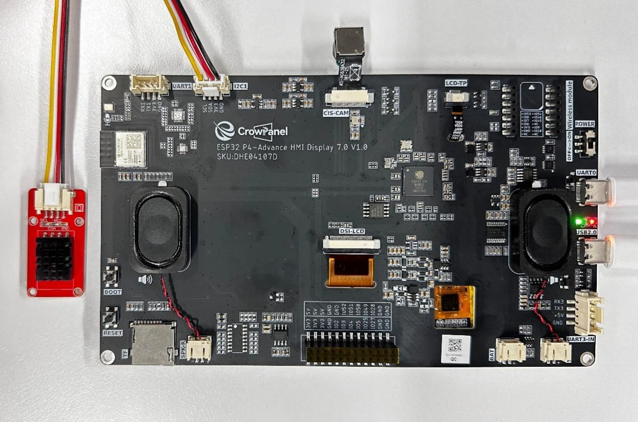
In this lesson, we will teach you how to use the I2C interface on the Advance-P4 board. We will connect a temperature and humidity sensor to the I2C interface, then display the values obtained from the sensor on the screen.
The key learning focus of this lesson is the use of the I2C interface. We will reuse the I2C component and screen display component covered in previous lessons, and additionally introduce a new temperature and humidity component: bsp_dht20.
Hardware Used in This Lesson
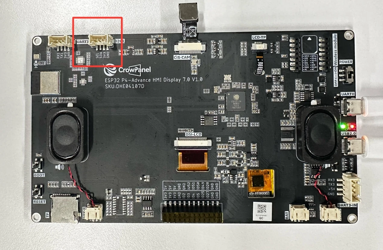
I2C Interface on the Advance-P4
temperature and humidity sensor Schematic Diagram

In the temperature and humidity sensor, humidity detection relies on hygroscopic materials. These materials absorb or release water in response to changes in environmental humidity, thereby altering their own electrical properties (such as resistance, capacitance, etc.). The sensor obtains humidity information by detecting the changes in the electrical signal between the material and the electrodes. Temperature detection typically uses thermal-sensitive elements (such as thermistors). When the temperature changes, the resistance value of the thermal-sensitive element changes. The sensor measures this resistance change and converts it to obtain the temperature value. Finally, it combines the data from both to determine the temperature and humidity conditions.
Operation Effect Diagram
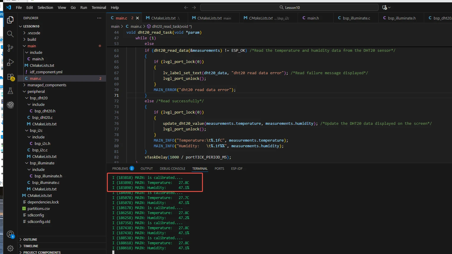
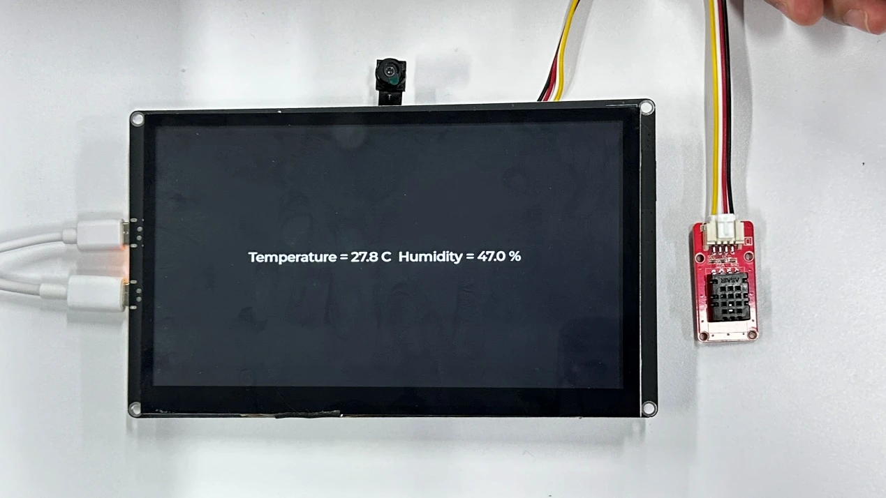
After running the code, you will be able to visually see the real-time temperature and humidity collected by the temperature and humidity sensor displayed on the screen of the Advance-P4.
Key Explanations
The focus of this lesson is on using the temperature and humidity sensor connected via the I2C interface. Here, we will prepare another new component for you: bsp_dht20. The main function of this component is to communicate with the DHT20 temperature and humidity sensor through the I2C bus, implementing functions such as sensor initialization, status detection, data reading, and verification to obtain environmental temperature and humidity data. You just need to know when to call the interfaces we have written in it. Next, let's focus on understanding the bsp_dht20 component. (The bsp_i2c component and bsp_dht20 component were explained in detail in previous courses.)
First, click on the GitHub link below to download the code for this lesson.
GitHub Link
Then drag the code for this lesson into VS Code and open the project file.
Once opened, you can see the framework of this project.
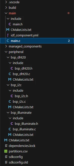
In the example for this lesson, a new folder named bsp_dht20 is created under the peripheral\ directory. Within the bsp_dht20\ folder, a new include folder and a "CMakeLists.txt" file are created.
The bsp_dht20 folder contains the "bsp_dht20.c" driver file, and the include folder contains the "bsp_dht20.h" header file.
The "CMakeLists.txt" file integrates the driver into the build system, enabling the project to utilize the temperature and humidity acquisition functions predefined in "bsp_dht20.c".
Temperature and Humidity Acquisition Code
The driver code for the temperature and humidity sensor consists of two files: "bsp_dht20.c" and "bsp_dht20.h".
Next, we will first analyze the "bsp_dht20.h" program.
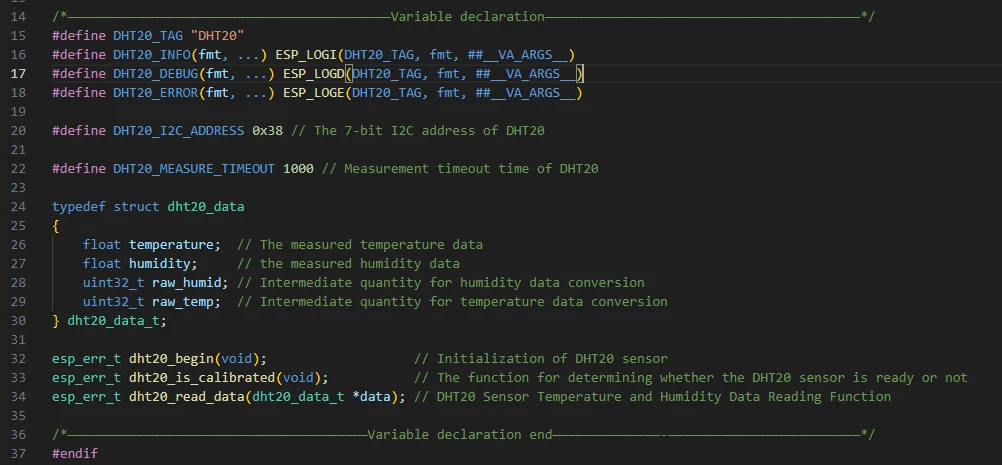
"bsp_dht20.h" is the header file for the temperature and humidity acquisition module, and its main purposes are:
-
To declare the functions, macros, and variables implemented in "bsp_dht20.c" for use by external programs. This allows other .c files to call functions from this module simply by adding #include "bsp_dht20.h".
-
In other words, it acts as an interface layer---it exposes which functions and constants are available for external use while hiding the internal implementation details of the module.
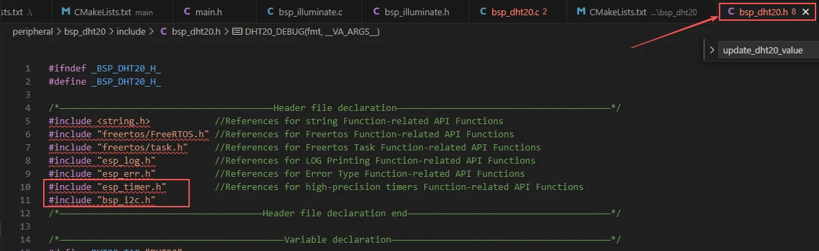
In this component, all the libraries we need to use are included in the "bsp_dht20.h" file, enabling unified management.
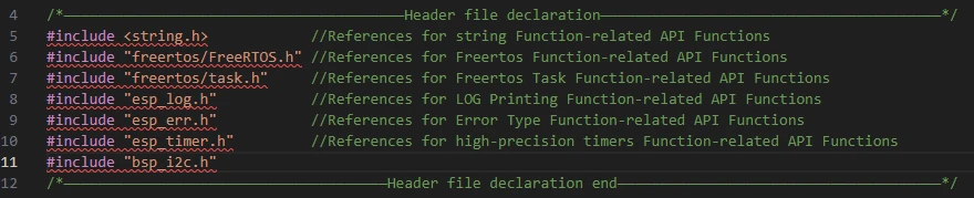
Then, we declare the variables we need to use, as well as the functions---whose specific implementations are in "bsp_dht20.c".
Centralizing these declarations in "bsp_dht20.h" is for the convenience of calling and management. (We will understand their roles when they are used in "bsp_dht20.c".)
Let's now examine the specific functions of each function in "bsp_dht20.c".
The bsp_dht20 component is primarily used to communicate with the DHT20 temperature and humidity sensor via the I2C bus. It implements functions such as sensor initialization, status detection, data reading, and verification to obtain environmental temperature and humidity data.
Then the following functions are the interfaces we call to initialize the temperature and humidity sensor and obtain its readings.
-
The 'print_binary' function: Its role is to convert a 16-bit integer 'value' into a corresponding binary string. It can be used in scenarios where data needs to be visually displayed in binary form, such as checking register values or the binary composition of sensor data.
-
The 'print_byte' function: This function splits an 8-bit byte 'byte' into high 4 bits and low 4 bits, then converts them into a binary string prefixed with '0b' to make the data more readable. It is useful when debugging I2C communication data that requires formatted printing of single-byte data, such as status bytes or data bytes returned by the sensor.
-
The 'dht20_reset_register' function: Its main function is to reset a specified register. The specific operation is to first read the current value of the register, then rewrite it according to the requirements of the DHT20 protocol. It can be used when sensor initialization fails or the status is abnormal, requiring resetting of key registers (such as calibration or configuration registers like '0x1B', '0x1C', '0x1E') to restore the sensor to normal working condition.
-
The dht20_status function: Sends the 0x71 command via I2C and reads the value of DHT20's status register to obtain the sensor's current working status, such as whether calibration is completed or a measurement is in progress. It is used to check if the sensor status is normal before initialization, confirm if the sensor is ready before measurement, or troubleshoot to identify the cause of abnormal sensor status.
-
The dht20_reset_sensor function: Continuously detects the sensor's status. If the status does not meet expectations (status value does not match 0x18, where 0x18 typically indicates calibration completion and readiness), it repeatedly resets key registers until the status is normal or the retry limit of 255 times is reached. It is used during sensor initialization (e.g., called in dht20_begin) to ensure the sensor enters a working state, or to attempt recovery after sensor communication anomalies.
-
The dht20_begin function: Initializes the DHT20 sensor through a process that registers the sensor's device address via I2C to obtain a handle, then calls dht20_reset_sensor to check and reset the sensor. It returns an error code if initialization fails. This function must be called during system startup or before the first use of the sensor; otherwise, subsequent data reading may fail.
-
The dht20_is_calibrated function: Checks if the sensor has completed calibration by determining whether a specific bit in the status register is 0x18---calibration completion is a prerequisite for the sensor's normal operation. It is used to confirm sensor readiness after initialization, verify normal sensor status before measurement, and avoid reading invalid data.
-
The dht20_crc8 function: Calculates the checksum of data using the CRC8 algorithm specified in the DHT20 protocol (polynomial 0x31) to verify the integrity of received data. It is used after reading sensor data (e.g., in dht20_read_data) to compare the calculated CRC value with the CRC byte returned by the sensor, determining if errors occurred during data transmission.
-
The dht20_read_data function: Fully implements the temperature and humidity data reading process, including sending measurement commands (0xAC, 0x33, 0x00), waiting for the sensor to complete measurement (with timeout detection), reading 7 bytes of data (including status, humidity, temperature, and CRC), and parsing raw data into actual temperature and humidity values (humidity in percentage, temperature in Celsius) after CRC verification. This core function of the component is called when environmental temperature and humidity need to be obtained, but it requires the sensor to be initialized and calibrated beforehand (confirmed via dht20_begin and dht20_is_calibrated).
That concludes our introduction to the bsp_dht20 component---you only need to understand how to call these interfaces.
If you need to call these interfaces, you must also configure the "CMakeLists.txt" file located in the bsp_dht20 folder.
This file, placed under the bsp_dht20 folder, mainly functions to tell the ESP-IDF build system (CMake): how to compile and register the bsp_dht20 component.
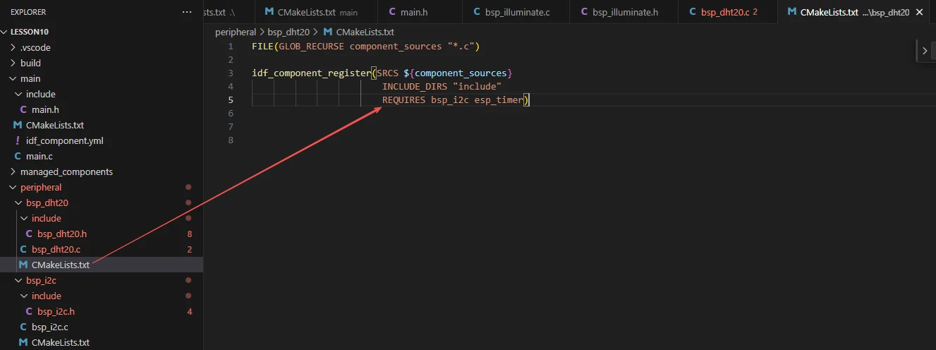
The reason we include bsp_i2c and esp_timer here is that they are explicitly used in "bsp_dht20.h". (Other system libraries do not need to be added because they are already integrated into the ESP-IDF framework by default.)
Main Function
The main folder is the core directory for program execution, containing the main function executable file main.c.
Add the main folder to the "CMakeLists.txt" file of the build system.
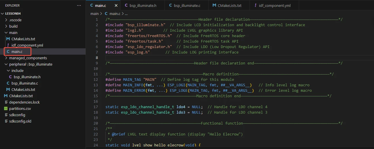
This is the entry file of the entire application. In ESP-IDF, there is no int main(); instead, the program starts running from void app_main(void).
Let's first explain main.c:
First, the Init function is called to initialize the following components in sequence: LDO power supply (to provide power for peripherals), I2C bus (the foundation for sensor communication), DHT20 sensor (to complete registration and status calibration), and display module. If initialization fails, an error is reported in a loop through init_fail.
After successful initialization, set the screen backlight to 100%, call dht20_display to create an LVGL white text label (with a black background, initially displaying default temperature and humidity), then create the read_dht20 task. This task cyclically checks the DHT20 calibration status every second (re-initializes if not calibrated), reads sensor data. If it fails, an error message is displayed on the screen; if successful, update_dht20_value is used to format and update the LVGL label to display real-time temperature and humidity.
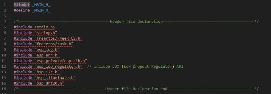
First is the reference to main.h, where we store the header files used and macro definitions.
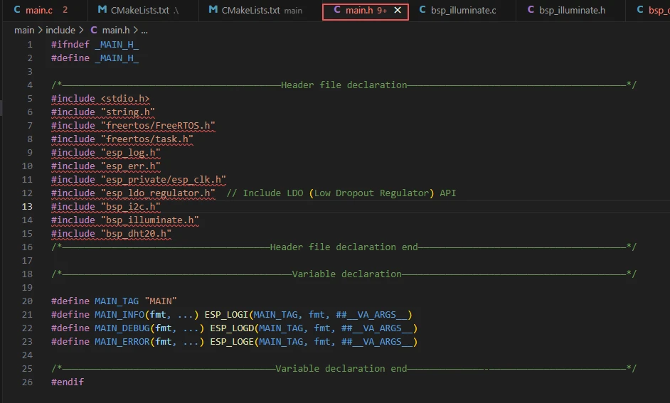
Here, it includes libraries for the three components used:
-
bsp_i2c: Since the temperature and humidity sensor communicates via I2C.
-
bsp_illuminate: Used for displaying temperature and humidity values on the screen.
-
bsp_dht20: For initializing the temperature and humidity sensor and obtaining its readings.
-
stdio.h, string.h: Provide basic input/output (e.g., printf) and string processing (e.g., memset, snprintf) functions, supporting operations such as data formatting.
-
freertos/FreeRTOS.h: This is the core header file of FreeRTOS, defining the basic types, macros, and data structures of the operating system, providing underlying support for task scheduling, time management, and memory management.
-
freertos/task.h: This is the header file for FreeRTOS task management, providing APIs for task operations such as creation, deletion, suspension, and delay, enabling the program to implement multi-task concurrent execution.
-
esp_ldo_regulator.h: This is the header file for the LDO (Low-Dropout Linear Regulator) control interface provided by ESP-IDF, allowing programs to apply for, configure, and control LDO channels to provide stable voltage for peripherals such as LCDs.
-
esp_log.h: This is the header file for the log printing interface of ESP-IDF, providing log output at different levels (INFO, ERROR, etc.), enabling developers to debug and track program running status.
-
esp_private/esp_clk.h: The private interface for ESP32 clock control (such as clock frequency configuration), ensuring stable system timing;
-
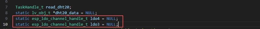
TaskHandle_t read_dht20;: Declares a FreeRTOS task handle, which is used to manage the lifecycle operations (such as creation and suspension) of the DHT20 data reading task.
-
static lv_obj_t *dht20_data = NULL;: Declares a LVGL text label pointer (visible only within the current file), initially set to NULL. It is used to point to and manipulate the on-screen label that displays temperature and humidity data.
The following two lines of code define the control handles for LDO channels 3 and 4. They are used to bind to actual LDO power channels during subsequent initialization, enabling the program to control power output at different voltages.
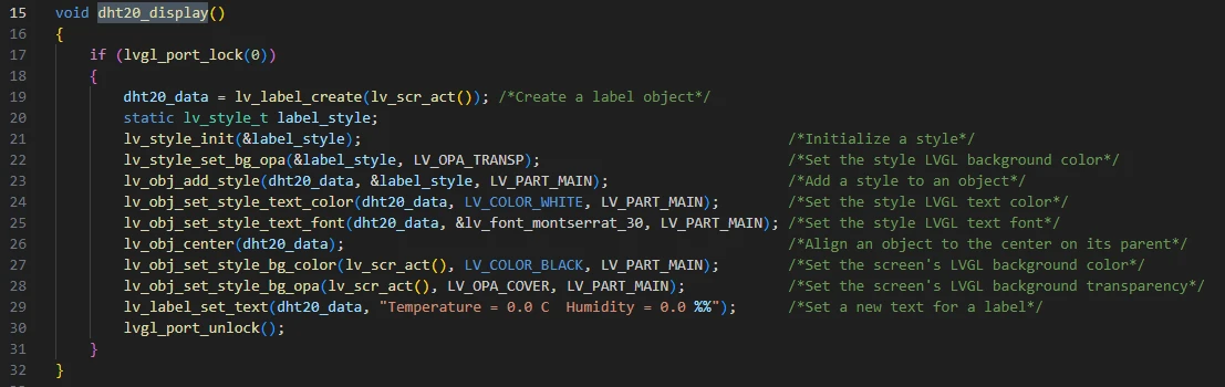
dht20_display():
This function is used to initialize the text label for displaying temperature and humidity data in the LVGL graphical interface:
First, it acquires the LVGL operation lock via lvgl_port_lock(0) (to avoid multi-task conflicts). Then, it creates a text label object dht20_data at the center of the screen, configures the label style (transparent background, white 30-point font), sets the screen to a black opaque background, and assigns the initial text "Temperature = 0.0 C Humidity = 0.0 %" to the label. Finally, it releases the LVGL lock, establishing a visual carrier for displaying real-time temperature and humidity data later.
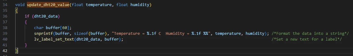
void update_dht20_value(float temperature, float humidity):
This function is used to update the display content of temperature and humidity data on the LVGL interface:
First, it checks whether the temperature and humidity display label dht20_data is valid. If valid, it uses snprintf to format the incoming temperature (temperature) and humidity (humidity) values into a string in the format of "Temperature = X.X C Humidity = X.X %". Then, it calls the LVGL interface lv_label_set_text to update the formatted string to the label, realizing real-time refresh of data on the screen.
void dht20_read_task(void *param):
This function is a FreeRTOS task function that executes periodically (every 1 second) in an infinite loop: It first checks if the DHT20 sensor is calibrated, and re-initializes it if not. If data reading fails, it displays an error message on the screen and prints a log. If reading succeeds, it updates the temperature and humidity data displayed on the screen and prints detailed logs, enabling continuous acquisition and visual display of sensor data.
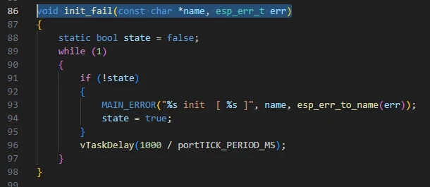
void init_fail(const char *name, esp_err_t err)
Function: When initialization of a module fails, this function is entered to run in an infinite loop, printing an error message (including the module name and error code string) once per second.
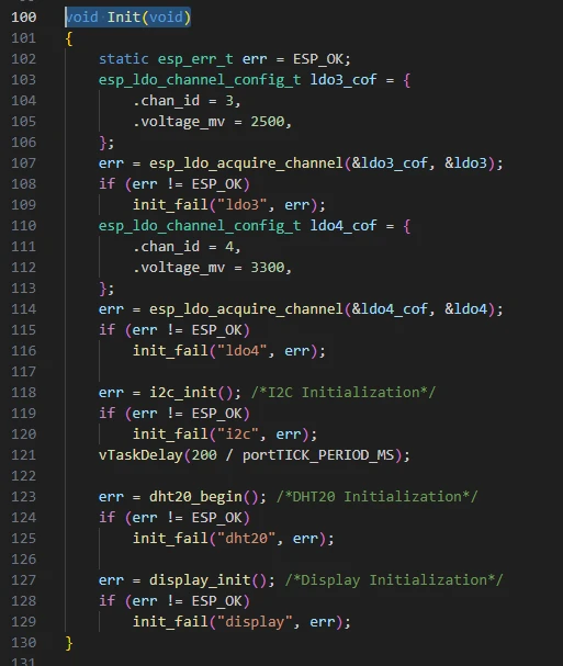
void Init(void):
This function is used for system initialization, which configures the LDO3 (2.5V) and LDO4 (3.3V) power channels, initializes the I2C bus (with a 200ms delay for stabilization), initializes the DHT20 sensor and display module in sequence. If any step of initialization fails, it calls the 'init_fail' function to output error messages in a loop, ensuring that subsequent operations are performed only after all hardware devices are ready.
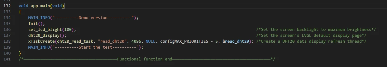
Then there is the main function 'app_main'.
'app_main' is the program entry function. It first prints the demo version information, then calls 'Init' to complete hardware initialization. Next, it sets the screen backlight to maximum brightness, initializes the LVGL display interface via 'dht20_display', and creates a task named "read_dht20" to periodically read and refresh temperature and humidity data. Finally, it prints a test start message, initiating the operation of the entire DHT20 temperature and humidity acquisition and display system.
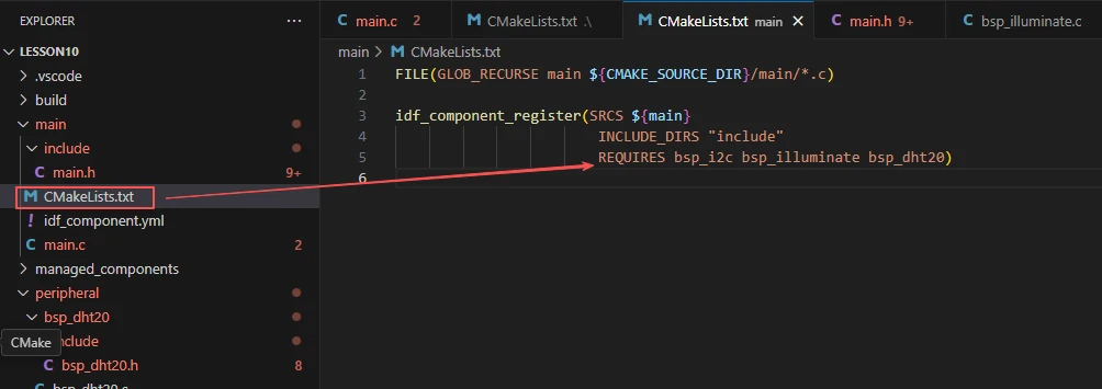
Finally, let's take a look at the "CMakeLists.txt" file in the main directory.
The role of this CMake configuration is as follows:
-
It collects all the .c source files in the main/ directory as the source files of the component.
-
It registers the main component with the ESP-IDF build system and declares that it depends on the custom components: bsp_dht20, bsp_illuminate, and bsp_i2c.
In this way, during the build process, ESP-IDF knows to build these three components first, and then build the main component.
Note: In the subsequent courses, we will not create a new "CMakeLists.txt" file from scratch. Instead, we will make minor modifications to this existing file to integrate other driver programs into the main function.
Complete Code
Kindly click the link below to view the full code implementation.
GitHub Link
Programming Steps
Now that the code is ready, next, we need to flash it to the ESP32-P4 to see the actual behavior.
First, we connect the Advance-P4 device to our computer via a USB cable.
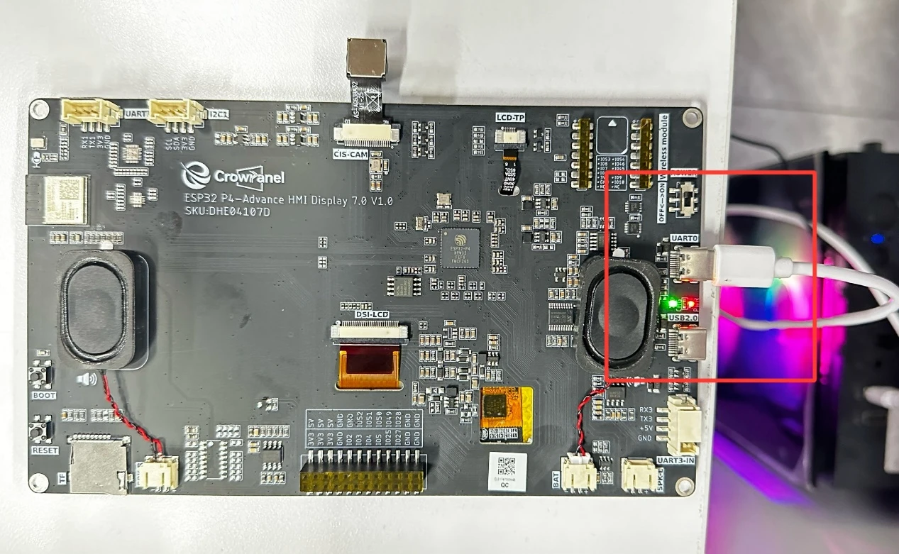
After connecting the Advance-P4 board, connect the temperature and humidity sensor to the I2C interface.
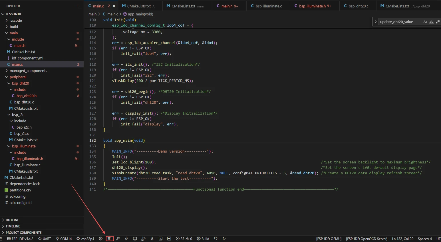
Before starting the preparation for flashing, first delete all files generated during compilation to restore the project to its initial "unbuilt" state. (This ensures that subsequent compilations are not affected by your previous build artifacts.)
First, follow the steps in the first section to select the ESP-IDF version, code upload method, serial port number, and target chip.
Next, we need to configure the SDK.
Click the icon shown in the figure below.

Wait for a short loading period, and then you can proceed with the relevant SDK configuration.

Then, search for flash in the search box.
(Make sure your flash configuration is consistent with mine.)
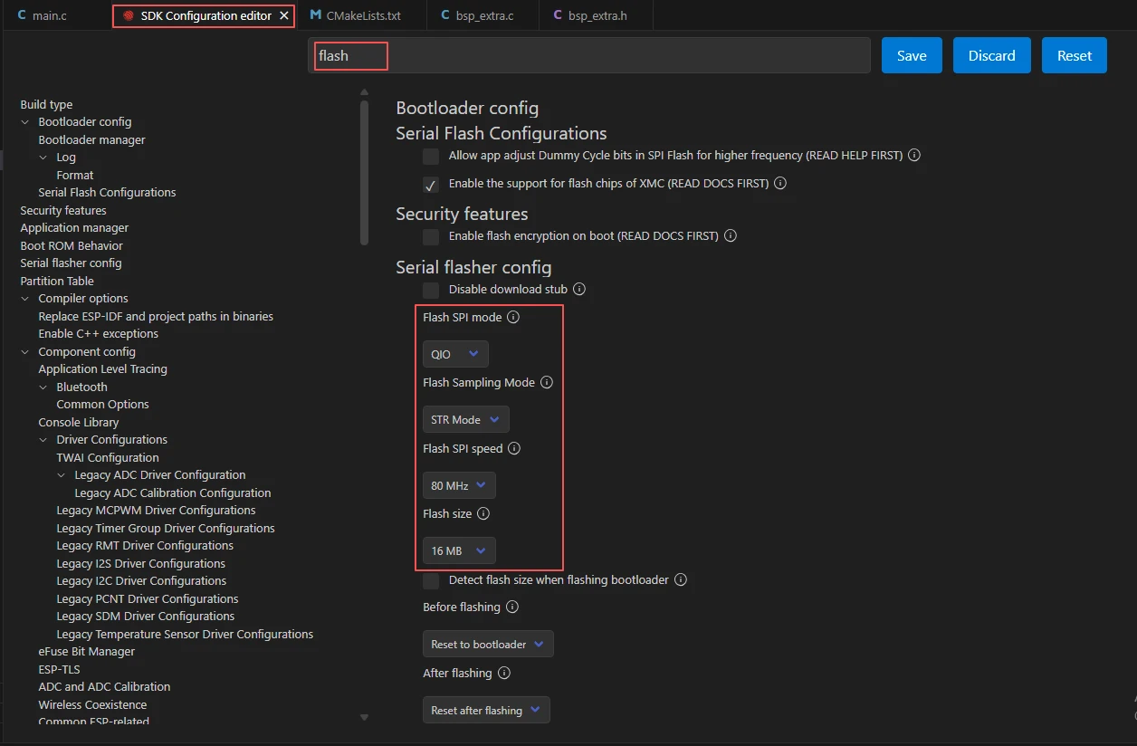
After completing the configuration, remember to save your settings.
Next, we will compile and flash the code (detailed in the first lesson).Here, we will also introduce a very convenient feature: you can execute compilation, upload, and open the monitor in one go with a single button (this works on the premise that the entire code is error-free).

Wait for a moment until the code compilation and upload are completed, and the monitor will open automatically.
After successful flashing, you will see that the screen of your Advance-P4 lights up, and the data collected by the temperature and humidity sensor is displayed on the screen in real time.