Lesson11---Playback After Recording
Introduction
In this lesson, we will teach you how to use the microphone and speaker on the Advance-P4 board. We will complete a project: record audio for 5 seconds, then automatically play back the 5-second audio clip.
Hardware Used in This Lesson
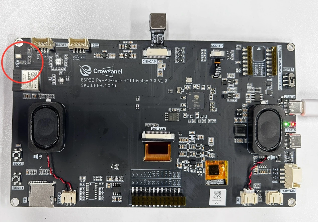
Microphone and Speaker on the Advance-P4

Microphone and Speaker Schematic Diagrams
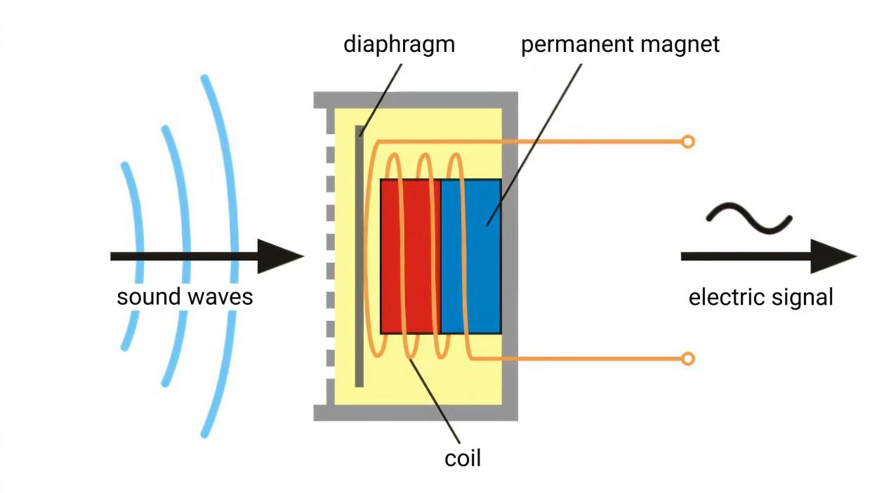
When an audio signal enters in the form of sound waves, it causes the diaphragm to vibrate. The diaphragm is connected to a coil, which is sleeved around a magnetic core (located in a magnetic field). The vibration makes the coil move in the magnetic field, cutting through the magnetic field lines. According to the law of electromagnetic induction, an electrical signal corresponding to the variation pattern of the audio signal is generated in the coil, thereby realizing the conversion of sound signals to electrical signals.(For a speaker, this is the reverse process of converting electrical signals to sound signals: an energized coil is forced to vibrate in a magnetic field, which drives the diaphragm to vibrate and produce sound.)
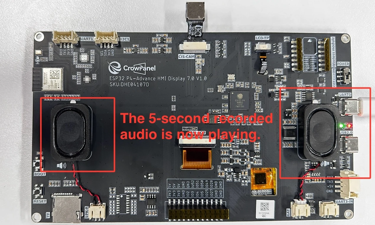
Operation Effect Diagram
After running the code, you will be able to speak near the Advance-P4. The Advance-P4 will use its microphone to record the current sound within 5 seconds, then play it back automatically.
Key Explanations
The key focus of this lesson is the use of two components: bsp_mic and bsp_audio. Next, we will explain the functions of the definitions and functions in these components respectively. What you need to know is when to call the pre-written interfaces in them.
Subsequently, we will focus on understanding these two components: bsp_mic and bsp_audio.
First, click the GitHub link below to download the code for this lesson.
GitHub Link
Then drag the code for this lesson into VS Code and open the project file.
Once opened, you can see the framework of this project.

In the example of this lesson, new folders named "bsp_mic" and "bsp_audio" are created under "peripheral".
In the "bsp_audio" folder, a new "include" folder and a "CMakeLists.txt" file are created. (The same applies to "bsp_mic".)
The "bsp_audio" folder contains the "bsp_audio.c" driver file, and the "include" folder contains the "bsp_audio.h" header file. (The same applies to "bsp_mic".)
The "CMakeLists.txt" file integrates the drivers into the build system, enabling the project to utilize the audio playback functions written in "bsp_audio.c" and the audio recording functions written in "bsp_mic.c".
Code for "bsp_audio"
Let's first look at the audio playback component, which includes two files: "bsp_audio.c" and "bsp_audio.h".
Next, we will first analyze the "bsp_audio.h" program.
"bsp_audio.h" is the header file for the audio playback module, mainly used to:
Declare the functions, macros, and variables implemented in "bsp_audio.c" for use by external programs, allowing other .c files to call this module simply by adding #include "bsp_audio.h".
In other words, it acts as an interface layer that exposes which functions and constants are available to the outside, while hiding the internal details of the module.
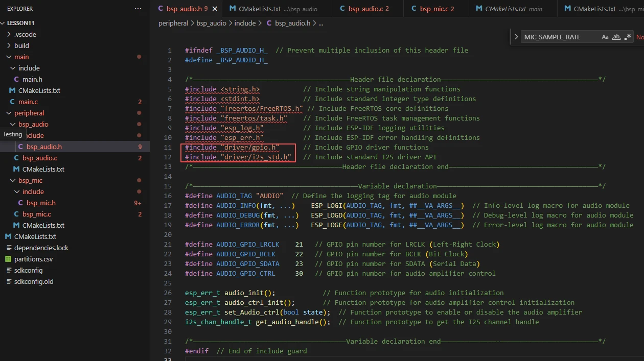
In this component, all the libraries we need to use are included in the "bsp_audio.h" file for unified management.

Then, we declare the variables we need to use, as well as the functions---whose specific implementations are in "bsp_audio.c".
Having these declarations unified in "bsp_audio.h" is for the convenience of calling and management. (We will learn about their roles when they are used in "bsp_audio.c".)
Let's take a look at the specific function of each function in "bsp_audio.c".
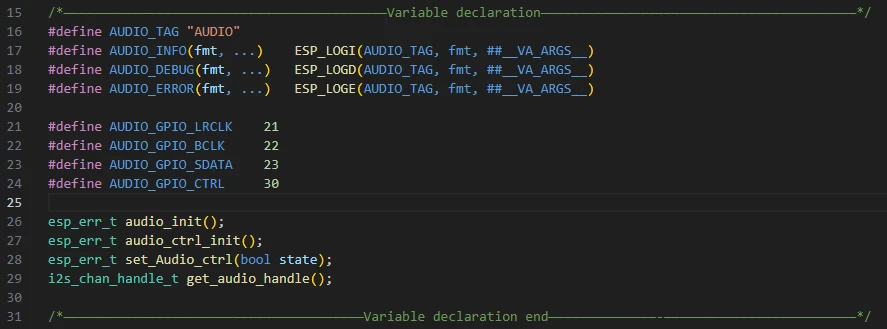
"bsp_audio.h": This project's custom audio module header file defines macros, GPIO pins, and function declarations.

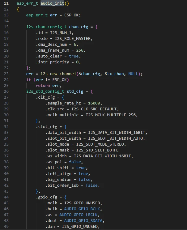
It defines a global variable tx_chan with the type i2s_chan_handle_t, which is an I2S channel handle.
This handle represents the audio output channel (TX), and all subsequent audio playback operations will be performed through this channel.

audio_init: This function is used to initialize and enable the I2S audio output channel. It configures parameters such as sample rate, bit width, clock, and pin settings, enabling the device to normally play audio data through the I2S interface.
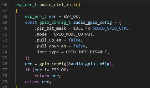
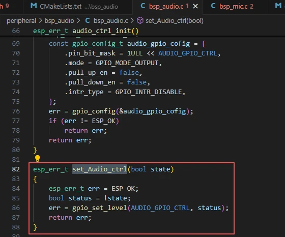
audio_ctrl_init: This function is used to initialize the audio power amplifier control pin, configuring it as an output mode to facilitate subsequent control of the power amplifier's on/off state.
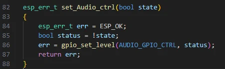
set_Audio_ctrl: This function is used to control the on/off state of the audio power amplifier. It enables or disables the power amplifier by setting the level of the power amplifier control pin (active low).
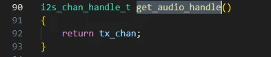
get_audio_handle: This function is used to obtain and return the handle of the current I2S audio output channel, allowing other modules to use this handle for audio data transmission or playback operations.
That concludes our introduction to the "bsp_audio" component. What's important is that you know how to call these interfaces.
If you need to use this component, you must also configure the "CMakeLists.txt" file under the "bsp_audio" folder.
This file, located in the "bsp_audio" folder, mainly functions to tell the ESP-IDF build system (CMake): how to compile and register the "bsp_audio" component.
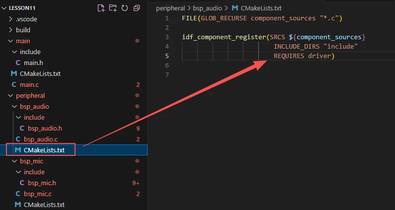
The reason why "driver" is included here is that we have called it in "bsp_audio.h" (other libraries are system libraries and do not need to be added).
Code for "bsp_mic"
Let's now look at how audio recording is implemented. Here, we'll directly examine the composition of functions in "bsp_mic.c".
First, let's look at "bsp_mic.h".
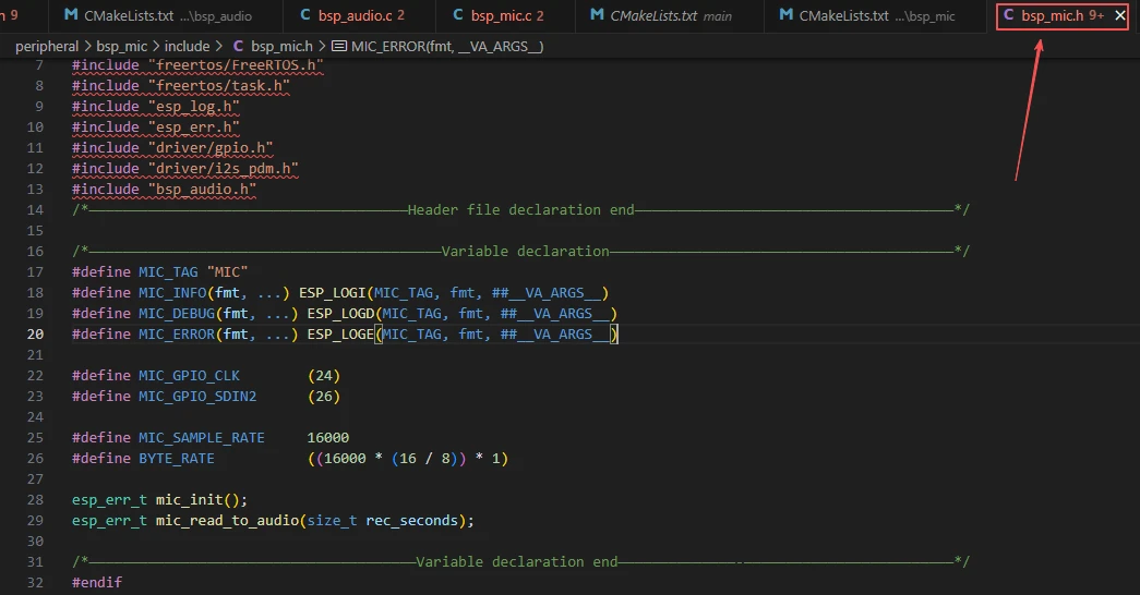
GPIO pins: MIC_GPIO_CLK (clock) and MIC_GPIO_SDIN2 (data input) specify the physical pins through which the microphone connects to the MCU. Audio sampling parameters: MIC_SAMPLE_RATE defines the sampling rate as 16 kHz, and BYTE_RATE calculates the amount of audio data generated per second (32,000 bytes), which is used for subsequent audio processing and storage management.
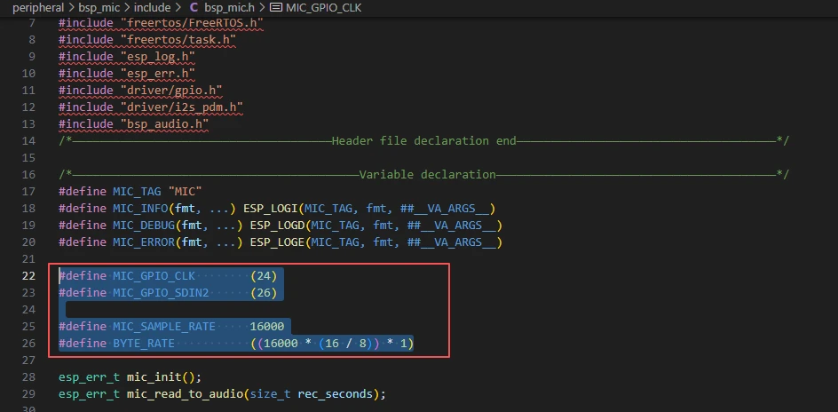
We'll stop here with the macro definitions in "bsp_mic.h" for now. During usage, there's no need to modify these - keep the pins unchanged and maintain the microphone's sampling rate. Next, let's look at "bsp_mic.c".
Two functions are implemented here to enable microphone recording and playback through audio output, using I2S PDM mode.
It mainly includes two functions: microphone initialization (mic_init) and recording to audio playback (mic_read_to_audio).
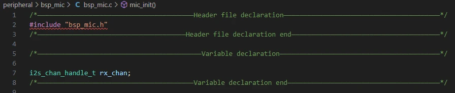
"bsp_mic.h": The header file for the microphone module, which defines macros, pins, and function declarations.
rx_chan: A global variable representing the I2S receive channel handle, which will be used for all subsequent operations involving reading audio data from the microphone.
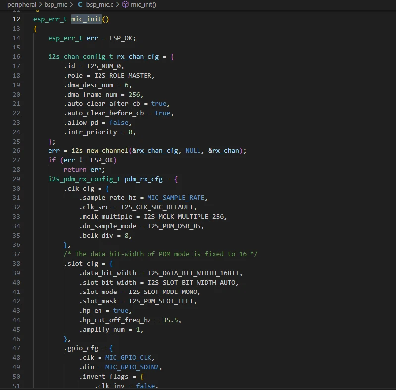
mic_init: This function is used to initialize the I2S receive channel (in PDM mode) for the microphone. It configures parameters such as the sampling rate, DMA buffer, GPIO pins, high-pass filter, and mono audio data format, and enables the channel. This allows the system to collect audio signals from the digital microphone.
mic_read_to_audio:
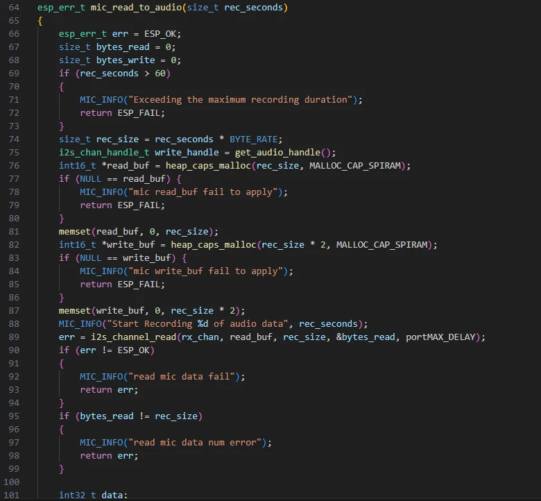
This function is used to record audio data from the microphone for a specified number of seconds and play it back in real time. Here's its detailed workflow:
First, it checks if the recording duration exceeds 60 seconds and calculates the required buffer size. Then, it dynamically allocates read_buf in SPI RAM to store the original mono audio data received from the I2S interface, and write_buf to store the processed stereo data for playback.
The function uses i2s_channel_read to block and read microphone data. For each audio sample, it performs volume amplification (multiplied by 10) and clipping processing to prevent overflow. It then copies the mono data to both left and right channels to form stereo data.
Subsequently, it turns on the power amplifier (set_Audio_ctrl(true)) and plays the processed audio through the audio output I2S channel. After playback is complete, it turns off the power amplifier and releases the buffer memory, ensuring the entire recording and playback process is safe and reliable.
(Please refer to the provided code for detailed implementation.)
Here, the set_Audio_ctrl function from "bsp_audio.c" is called to turn on the power amplifier pin, enabling sound playback.

Main Function
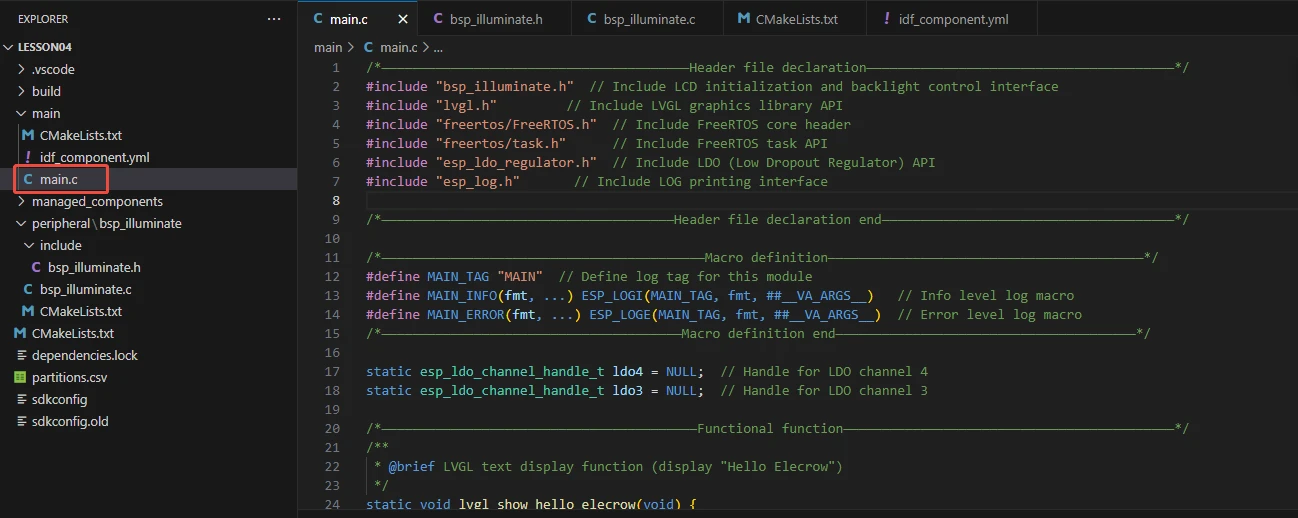
The main folder is the core directory for program execution, which contains the main function executable file "main.c".
Add the main folder to the "CMakeLists.txt" file of the build system.
This is the entry file of the entire application. In ESP-IDF, there is no int main(), and the program starts running from void app_main(void).
Let's first explain "main.c".
The app_main function is the main entry point of the entire application, responsible for coordinating the initialization of the audio system and microphone, as well as handling recording and playback.
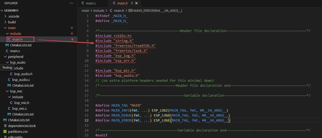
First, there is the reference to "main.h". We store the header files used and macro definitions in "main.h".
-
Include C standard libraries and string manipulation libraries to provide basic functions.
-
Include FreeRTOS task and scheduling interfaces for task creation and delay functions.
-
Include ESP-IDF logging and error handling interfaces (esp_log.h, esp_err.h).
-
Include header files of the microphone and audio modules to access interfaces such as mic_init(), mic_read_to_audio(), and audio_init().
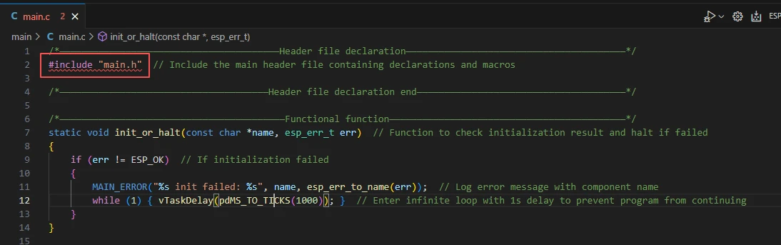
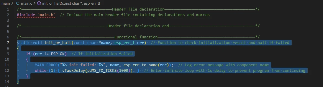
The function "init_or_halt" is designed to uniformly check the return status of each module's initialization. It ensures the system does not continue running when the initialization of critical hardware or peripherals fails, thereby preventing undefined behavior or hardware damage.
Specifically, it accepts two parameters: the module name "name" and the initialization result "err". If "err" is not equal to "ESP_OK", it indicates a failed initialization. In this case, the function will print a detailed error log (including the module name and error information) via "MAIN_ERROR", then enter an infinite loop with a 1-second delay in each loop iteration to prevent the program from proceeding further.
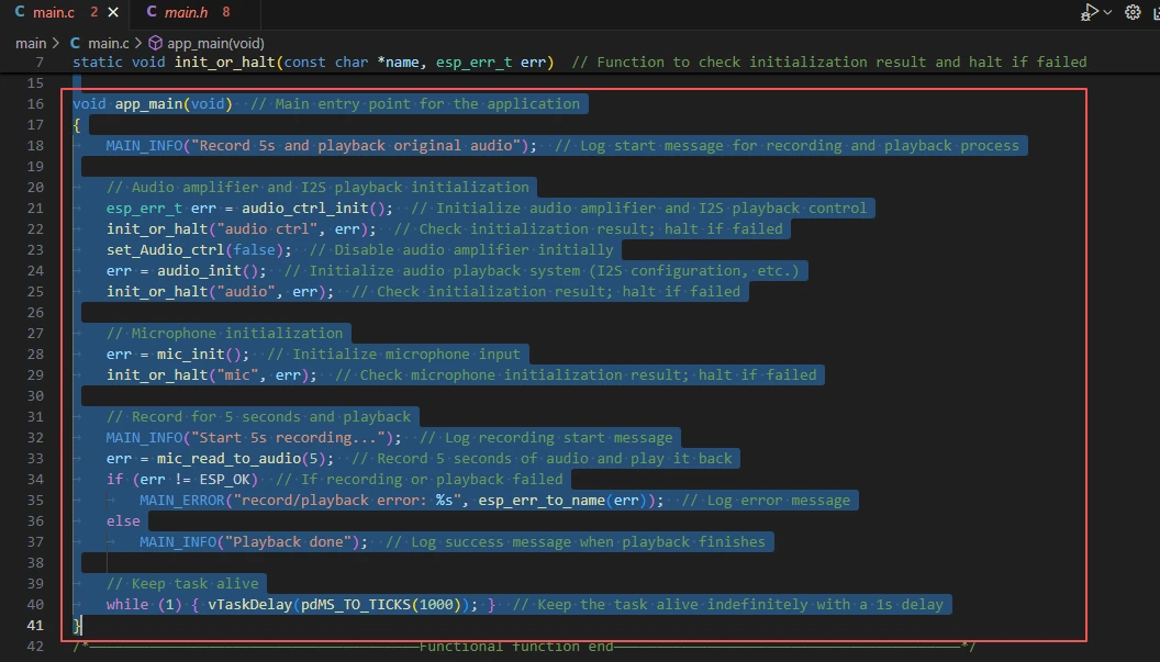
Next is the main function "app_main".
The "app_main" function serves as the primary entry point of the entire application, responsible for coordinating the initialization of the audio system and microphone, as well as audio recording and playback.
It first initializes the audio power amplifier and the I2S playback channel, and uses "init_or_halt" to check if the initialization is successful. If the initialization fails, the program will get stuck in an infinite loop. Subsequently, it initializes the microphone input channel and also verifies the success of this initialization. After that, the program will record audio for 5 seconds and play it back via I2S. During this process, it prints log information to indicate the recording and playback status, and records error messages when errors occur.
Finally, the function enters an infinite loop to keep the task alive, ensuring that the main program does not exit and thus maintaining the operating environment of the audio system. On the whole, this function implements a complete sample workflow for audio recording and playback.
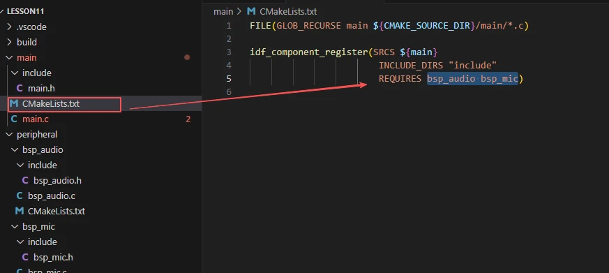
Finally, let's take a look at the "CMakeLists.txt" file in the main directory.
The role of this CMake configuration is as follows:
-
Collect all .c source files in the main/ directory and use them as the source files of the component;
-
Register the main component to the ESP-IDF build system, and declare that it depends on the custom components "bsp_audio" and "bsp_mic".
In this way, during the build process, ESP-IDF will know to build these two components first, and then build the main component.
Note: In the subsequent courses, we will not create a new "CMakeLists.txt" file from scratch. Instead, we will make minor modifications to this existing file to integrate other drivers into the main function.
Complete Code
Kindly click the link below to view the full code implementation.
GitHub Link
Programming Steps
Now that the code is ready, next, we need to flash it to the ESP32-P4 to observe the actual behavior.
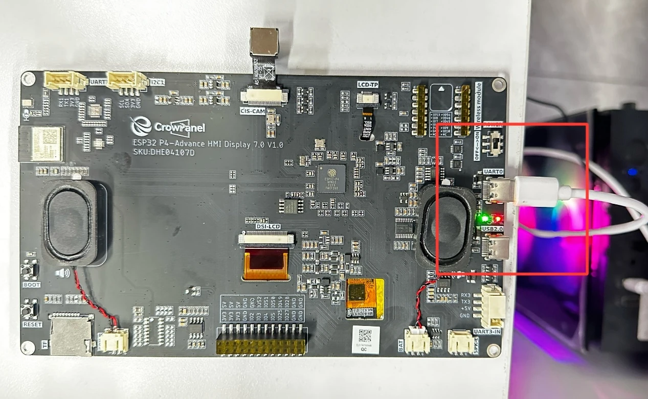
First, connect the Advance-P4 device to your computer via a USB cable.
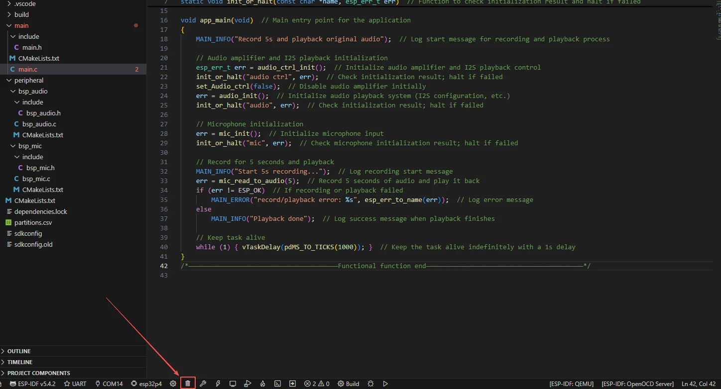
Before starting the flashing preparation, delete all files generated during compilation to restore the project to its initial "unbuilt" state. (This ensures that subsequent compilations are not affected by your previous operations.)
Here, follow the steps from the first section to select the ESP-IDF version, code upload method, serial port number, and target chip first.
Next, we need to configure the SDK.
Click the icon shown in the figure below.
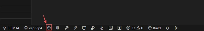
After waiting for a short loading period, you can proceed with the relevant SDK configurations.

Subsequently, search for "flash" in the search box.
(Make sure your flash configuration is the same as mine.)
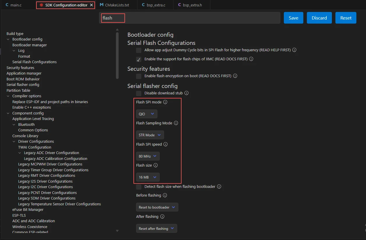
After completing the configuration, remember to save your settings.
Next, we will compile and flash the code (detailed steps were covered in the first lesson).
Here, we also want to share a very convenient feature with you: there is a single button that allows you to execute compilation, upload, and monitor opening in one go. (This is on the premise that the entire code is confirmed to be error-free.)

Wait for a moment, and the code will finish compiling and uploading, with the monitor opening automatically afterward.
Once the flashing is successful, you can speak near the Advance-P4 device. The Advance-P4 will use its microphone to record the current sound within 5 seconds, and then play it back automatically.