Lesson13---Camera Real-Time
Introduction
In this lesson, we will start teaching you how to activate the camera, enabling real-time display of the camera feed on the Advance-P4 screen.
Hardware Used in This Lesson
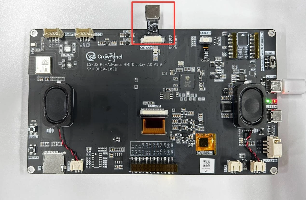
The camera on the Advance-P4
Camera Schematic Diagram
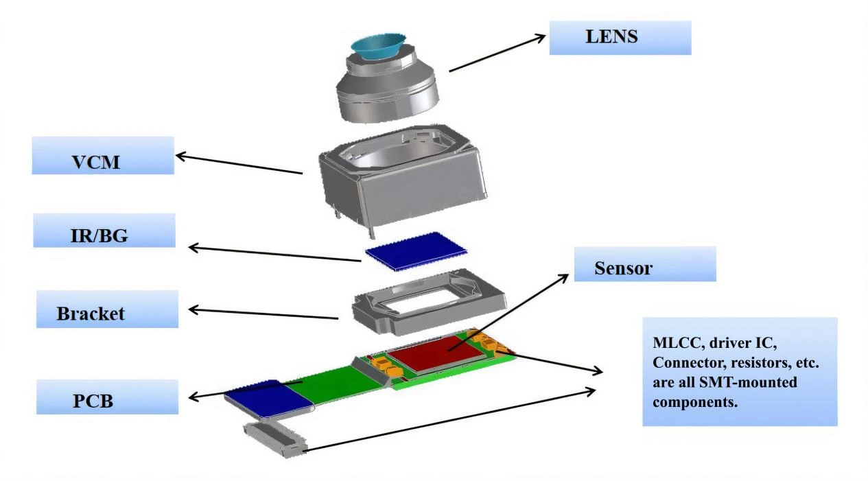
First, the lens serves as a "collector" of light. Its optical structure can capture light from external scenes and, through its curvature and other design features, converge this light to provide a basic optical signal for subsequent imaging.
Next, the Voice Coil Motor (VCM) plays a key role in autofocus. Based on control signals from the circuit, it uses the principle of electromagnetic induction to drive the lens to move precisely within a certain range. By changing the distance between the lens and the image sensor (Sensor), it adjusts the focal point of the light, ensuring that the object being photographed is clearly imaged on the Sensor. Before the light reaches the Sensor, the IR cut/blue glass filter (IR/BG) filters the light. The IR cut filter blocks infrared light, as infrared light can interfere with visible light imaging and cause color distortion. The blue glass filter not only blocks infrared light but also reduces the entry of stray light, further improving light purity and making the light received by the subsequent Sensor more conducive to forming images with accurate colors and clarity.
Then, the image sensor (Sensor), as a core component, is covered with photosensitive elements such as photodiodes on its surface, which convert the received optical signals into electrical signals. Light of different intensities causes the photosensitive elements to generate electrical signals of different magnitudes, corresponding to information such as brightness and color in the scene.
Finally, components such as Multilayer Ceramic Capacitors (MLCC), driver integrated circuits (driver ICs), connectors, and resistors mounted on the Printed Circuit Board (PCB) form a complete signal processing and transmission system through circuit connections. The driver IC is responsible for preliminary processing of the electrical signals generated by the Sensor, such as amplification and analog-to-digital conversion, converting analog electrical signals into digital signals. Capacitors like MLCC and resistors stabilize voltage, filter noise, and ensure the stable operation of the circuit.
The digital signals processed in this way are then transmitted through connectors to subsequent devices (such as the main control chips of mobile phones and cameras), and finally decoded and rendered into the digital images we see.
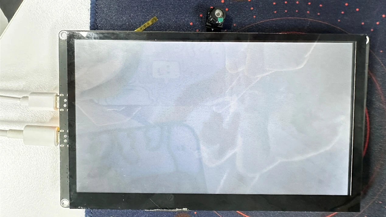
Operation Effect Diagram
After running the code, you will be able to see the real-time feed from the camera displayed on the screen of the Advance-P4.
Key Explanations
Now, the key focus of this lesson is how to use the camera and display the camera feed on the screen.
Here, we will prepare another new component for you: "bsp_camera".
The main functions of this component are as follows:
-
Initialize the camera hardware (including I2C communication, MIPI CSI interface, and ISP (Image Signal Processing)).
-
Implement ISP (Image Signal Processing) workflows such as Auto Exposure (AE), Auto White Balance (AWB), and Color Correction Matrix (CCM).
-
Acquire real-time image data from the camera and display it on the screen (using the LVGL graphics library).
-
Provide functions for refresh control, display control, and buffer control.
You just need to know when to call the interfaces we have written.
Next, let's focus on understanding the "bsp_camera" component.
First, click the GitHub link below to download the code for this lesson.
GitHub Link
Then drag the code for this lesson into VS Code and open the project file.
Once opened, you can see the framework of this project.
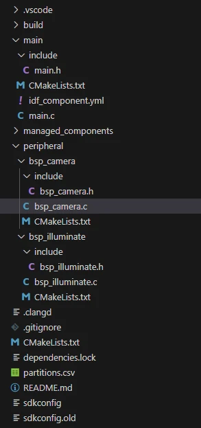
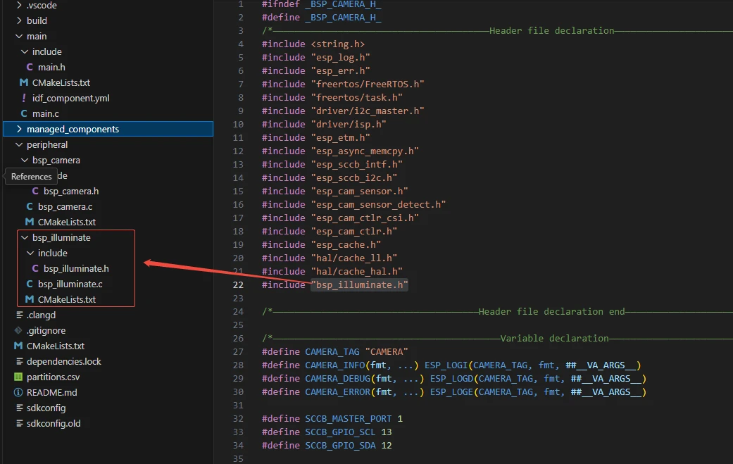
In the example of this lesson, a new folder named "bsp_camera" has been created under "peripheral". Within the "bsp_camera" folder, a new "include" folder and a "CMakeLists.txt" file have been created.
The "bsp_camera" folder contains the driver file "bsp_camera.c", and the "include" folder contains the header file "bsp_camera.h".
The "CMakeLists.txt" file integrates the driver into the build system, enabling the project to utilize the camera initialization and related display functions written in "bsp_camera.c".
Camera Display Code
The camera display code consists of two files: "bsp_camera.c" and "bsp_camera.h".
Next, we will first analyze the "bsp_camera.h" program.
"bsp_camera.h" is the header file for camera display, mainly used to:
Declare the functions, macros, and variables implemented in "bsp_camera.c" for use by external programs;
Allow other .c files to call this module simply by adding #include "bsp_camera.h".
In other words, it serves as an interface layer that exposes which functions and constants are available to the outside, while hiding the internal details of the module.
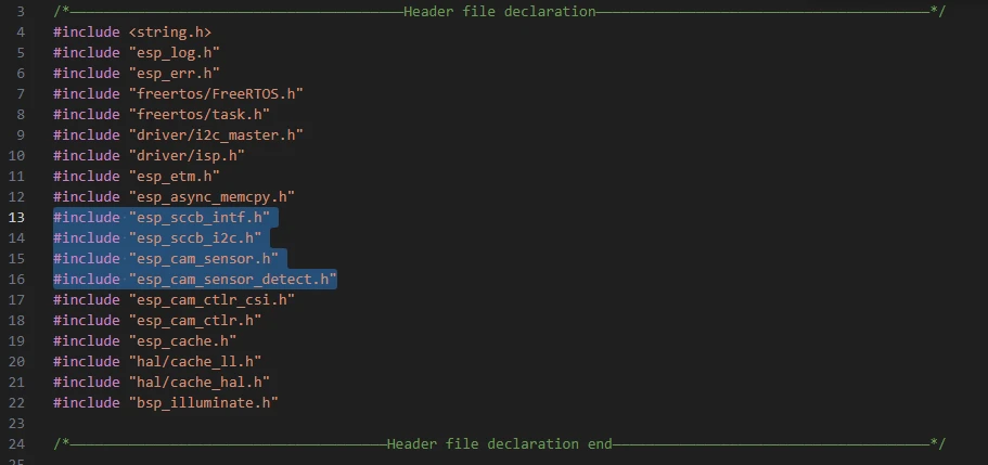
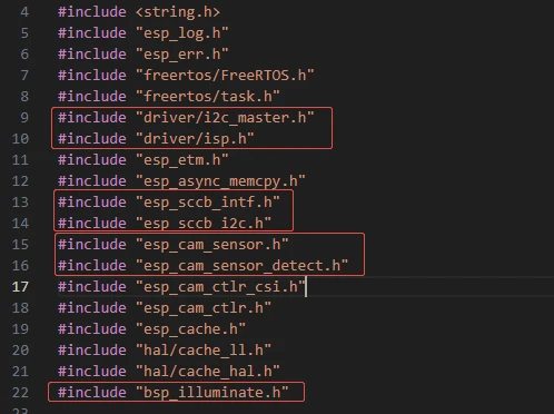
In this component, all the libraries we need to use are included in the "bsp_camera.h" file for unified management.

Such as "esp_sccb_intf.h", "esp_sccb_i2c.h", "esp_cam_sensor.h", "esp_cam_sensor_detect.h", and so on (these are all libraries under the network component).
We need to fill in the versions of "esp_cam_sensor", "esp_cam_sensor", and "esp_cam_sensor" in the "idf_component.yml" file under the main folder.
Since these are official libraries, we need to rely on them to implement the camera functionality on our Advance-P4.
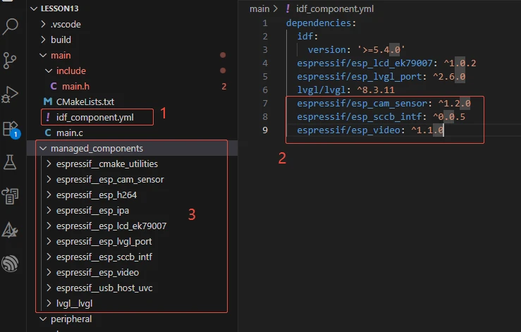
During subsequent compilation, the project will automatically download the esp_cam_sensor library version 1.2.0, esp_cam_sensor version 0.0.5, and esp_video version 1.1.0. Once the download is complete, these network components will be stored in the "managed_components" folder (which is automatically generated after filling in the version numbers).
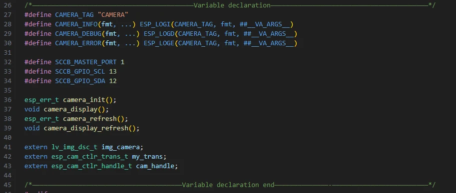
Next, we need to declare the variables we will use and the functions whose specific implementations are in "bsp_camera.c".
Centralizing these declarations in "bsp_camera.h" facilitates easier calling and management. (We will explore their specific roles when they are used in "bsp_camera.c".)
Let's take a look at the specific functions of each function in "bsp_camera.c".
The "bsp_camera" component provides significant support for everyone to use the camera later. By understanding the role of each function clearly, you can use the camera conveniently.
We won't explain the code in detail here; we\'ll only tell you what each function does and under what circumstances to call it.
1.example_isp_awb_on_statistics_done_cb()
Function:
This is a callback function for the Auto White Balance (AWB) module in the ISP (Image Signal Processor). It is called when the AWB module completes its statistics calculation.
Currently, it simply returns true to indicate "default processing after statistics completion" and has no actual operational logic.
Calling Timing:
Automatically invoked by the underlying ISP driver (when the ISP finishes the white balance statistics for a single frame of image).
2. camera_get_new_vb()
Function:
Provides a new frame buffer for the Camera Controller.
When the camera is ready to capture a new frame of image, the driver will call this function to obtain the memory address of the buffer.
Calling Timing:
Automatically invoked by the underlying camera driver, when the controller detects that it can capture a new frame of image.
3. camera_get_finished_trans()
Function:
Used to notify that the transmission of a frame of image has been completed.
Currently, the function does nothing internally (it simply returns false), meaning no special processing is temporarily required for the completed image.
Calling Timing:
Automatically invoked by the camera controller, triggered when the transmission of a frame of data from the camera to memory is completed.
4. camera_sensor_init()
Function:
Initializes the operating parameters and communication interface of the camera sensor itself.
It mainly includes the following steps:
-
Initialize SCCB (I2C bus) communication;
-
Automatically detect the model of the connected camera;
-
Set resolution, pixel format (RAW8), and frame rate;
-
Set mirroring (horizontal flip), exposure time, and exposure value;
-
Enable video data stream output.
Calling Timing:
During the overall camera system initialization (called within camera_init()).
5. camera_csi_init()
Function:
Initializes the camera's MIPI-CSI interface controller, which is the module responsible for receiving camera data streams.
It mainly completes the following tasks:
-
Configure CSI controller parameters (resolution, data rate, number of channels, etc.);
-
Register data transmission callbacks (camera_get_new_vb, camera_get_finished_trans);
-
Enable the controller.
Calling Timing:
Also during the camera initialization phase (called within camera_init()).
6. isp_init()
Function:
Initializes the ISP (Image Signal Processor) module.
The ISP is responsible for processing the raw image data (RAW data) output by the camera to convert it into RGB images.
This includes:
-
Enabling the main ISP module;
-
Setting color adjustment parameters (brightness, contrast, saturation, hue);
-
Enabling the Auto White Balance (AWB) controller;
-
Enabling the Auto Exposure (AE) controller;
-
Enabling the Color Correction Matrix (CCM).
Calling Timing:
During the camera initialization phase (called within camera_init()).
7. camera_init()
Function:
This is the "main initialization function" for the entire camera subsystem.
It is responsible for:
-
Allocating image buffers for the camera (located in external PSRAM);
-
Calling the three core initialization functions mentioned earlier:
camera_sensor_init() → Initializes the camera sensor;
camera_csi_init() → Initializes the image reception interface;
isp_init() → Initializes image signal processing;
- Starting the camera data stream acquisition.
Calling Timing:
When the system powers on (usually called once in app_main() or during the device initialization phase).
8. camera_refresh()
Function:
Manually triggers the camera to capture a frame of image.
Essentially, it calls esp_cam_ctlr_receive() to receive a frame of image data.
Calling Timing:
Invoked when the application layer needs to refresh the camera image, such as:
-
The first capture after program startup;
-
Manual refresh by the user;
-
Periodic calls in timed tasks.
9. camera_display_refresh()
Function:
Notifies LVGL to refresh the camera feed display area.
It calls lv_obj_invalidate(), which prompts LVGL to redraw the camera image in the next rendering cycle.
Calling Timing:
camera_display_task()).
10. camera_display()
Function:
Creates an image object in LVGL for displaying the camera feed.
The specific steps are as follows:
-
Create an lv_img object;
-
Set center alignment for the object;
-
Bind the image buffer (RGB565 data captured by the camera);
-
Configure the image source;
-
Unlock LVGL to allow rendering.
Calling Timing:
Called once after the camera is initialized successfully, to create and display the image control (invoked within Init()).
This concludes our introduction to the bsp_camera component. For your purposes, it is sufficient to know how to call these interfaces.
If you need to call these interfaces, you must also configure the "CMakeLists.txt" file under the bsp_camera folder.This file, located in the bsp_camera folder, primarily functions to tell the ESP-IDF build system (CMake): how to compile and register the bsp_camera component.
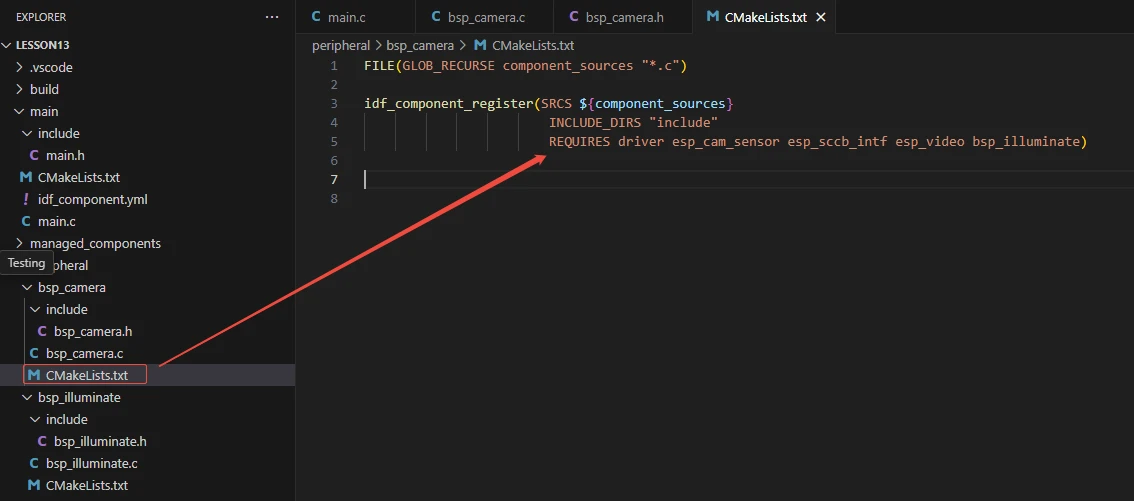
The reason for including "driver", "esp_cam_sensor", "esp_sccb_intf", "esp_video", and "bsp_illuminate" is that we have called these in "bsp_camera.h" (other libraries that are system libraries do not need to be added).
For example, "bsp_illuminate.h" is a component related to screen display that we explained earlier. Since it was covered in detail before, we won't go into it again here.
It is used to initialize the screen, turn on the screen backlight, and enable the screen to display relevant content.
Main Function
The main folder is the core directory for program execution, which contains the main function executable file main.c.
Add the main folder to the "CMakeLists.txt" file of the build system.
This is the entry file of the entire application. There is no int main() in ESP-IDF; instead, the program starts running from void app_main(void).
First, let's explain "main.c".
When the program runs, the general process is as follows:
During program execution, the system first calls Init() in app_main() to initialize hardware and modules: configure the LDO power supply, GPIO interrupts, LCD display and backlight, and initialize the camera and display buffer.
After initialization is completed, the program first captures a frame of camera feed, then creates the camera_display_task task and enters a loop: lock LVGL, refresh the camera display, unlock LVGL, and delay for approximately 23ms. This loop continuously updates the frame, enabling real-time camera display.
Next, let's explain the main code "main.c".

It includes the custom main header file "main.h", which typically contains log macros, peripheral initialization declarations, and header files of other interfaces that need to be used.
Below is the content within "main.h":

Let's continue to look at the content in "main.c".
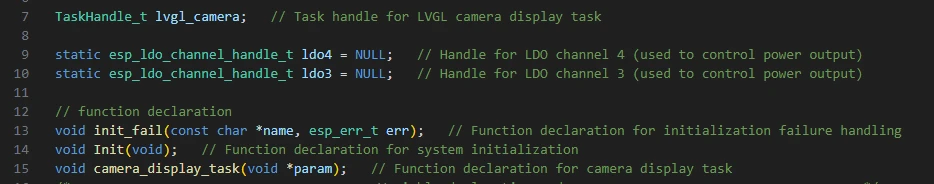
lvgl_camera: A handle for the LVGL display task, used to manage the display task.
LDO power control handles: Used to supply power to peripherals (such as the camera and LCD).
ldo3 corresponds to a 2.5V output.
ldo4 corresponds to a 3.3V output.
Function declarations:
init_fail: Handles initialization failure.
Init: Performs system hardware initialization.
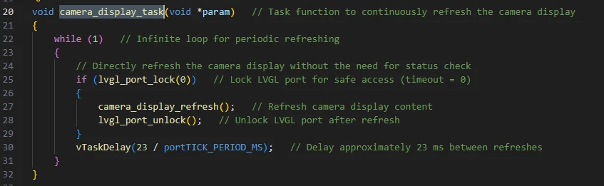
camera_display_task: Implements the camera display refresh task.
camera_display_task:
A FreeRTOS task function used to continuously refresh the camera display.
Core Process:
-
Infinite loop while(1).
-
Attempt to acquire the LVGL lock via lvgl_port_lock(0).
-
If the lock is successfully acquired, call camera_display_refresh() to update the display buffer to the screen.
-
Unlock LVGL with lvgl_port_unlock().
-
Delay for 23ms (vTaskDelay) to control the refresh rate, approximately 43 FPS.
Once the task is created after program startup, it will continuously refresh the camera display.
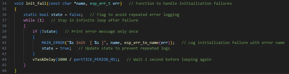
init_fail:
Initialization failure handling function:
-
Uses static bool state to prevent repeated printing.
-
Runs in an infinite loop, printing initialization failure messages.
-
Delays for 1 second per cycle.
Function:
Once any hardware initialization fails, the program stops further execution and prints error messages.
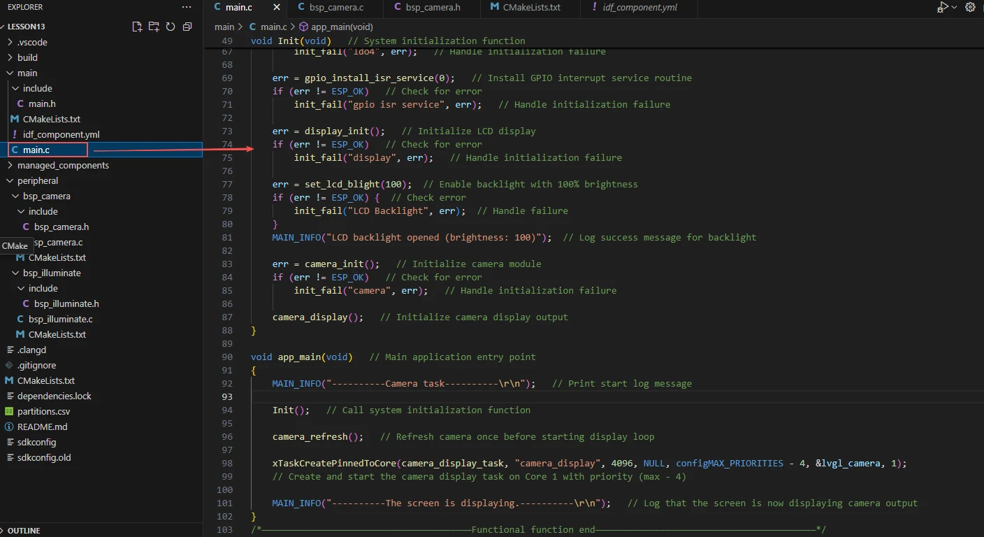
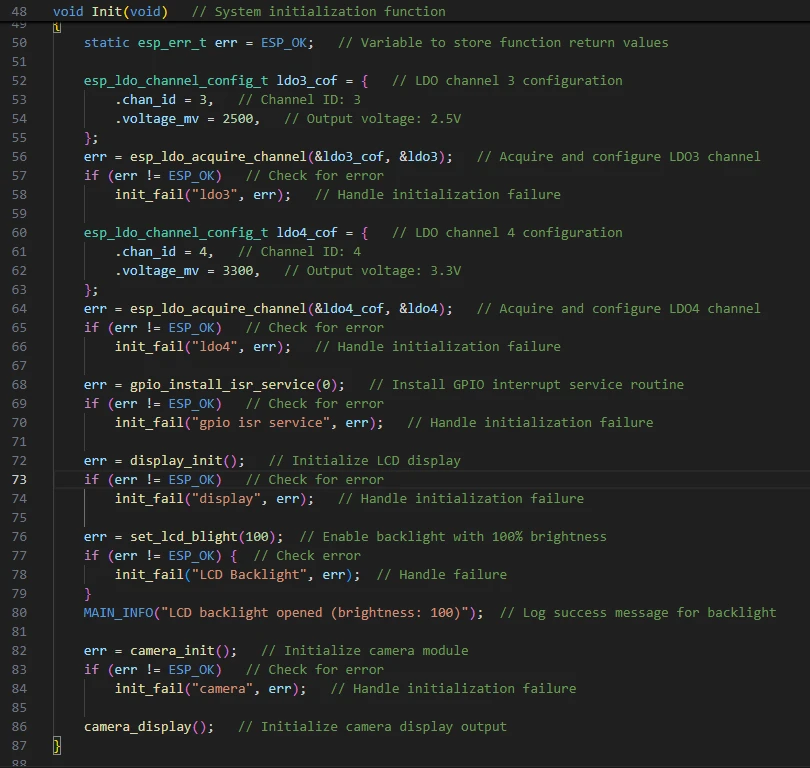
Init:
Hardware initialization function during system startup.
Initialization Steps:
-
Configure LDO3 (2.5V) and LDO4 (3.3V) to supply power to the LCD.
-
Install the GPIO interrupt service via gpio_install_isr_service.
-
Initialize the LCD display with display_init().
-
Turn on the LCD backlight using set_lcd_blight(100).
-
Initialize the camera module with camera_init().
-
Initialize the camera display with camera_display().
Calling Scenario:
Invoked once within app_main() when the program starts.
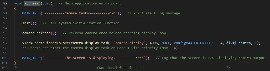
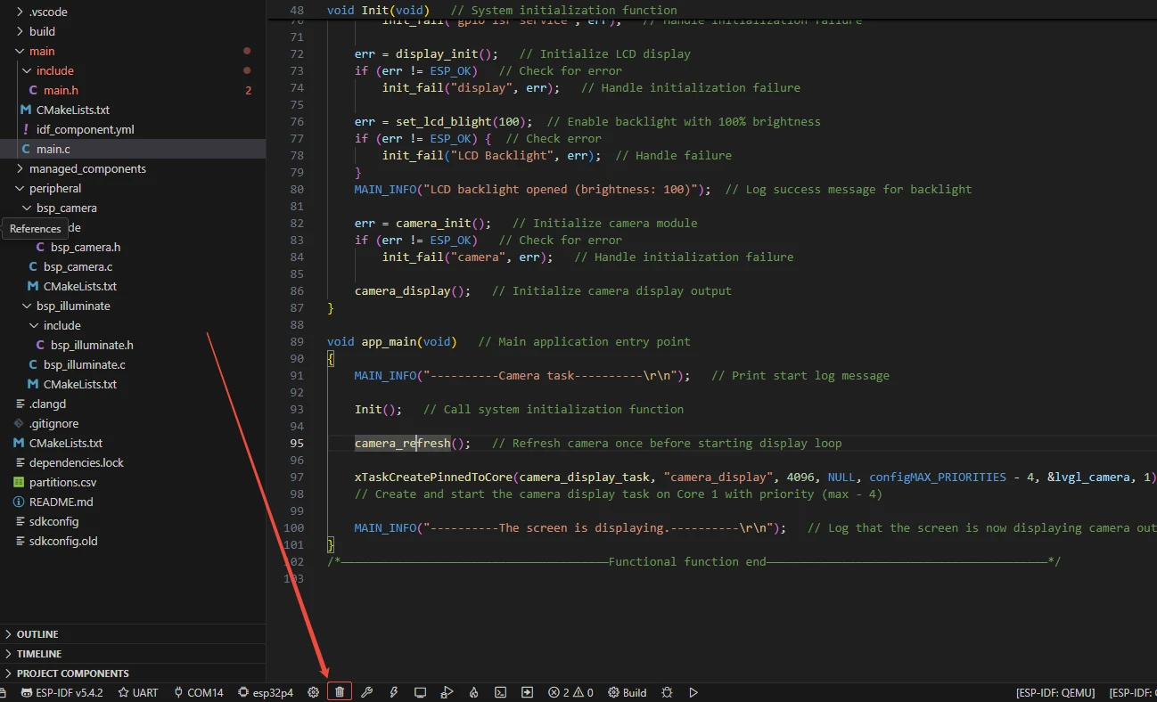
app_main:
The program entry point for ESP32 FreeRTOS.
Process:
-
Print the log "Camera task".
-
Call Init() to initialize the system.
-
Call camera_refresh() to retrieve a new frame of image data from the camera controller into the buffer, providing the latest frame for subsequent display or processing.
-
Create the camera_display_task task, attach the display task to Core 1 with a relatively high priority.
-
Print the log "The screen is displaying" to indicate that the display has started.
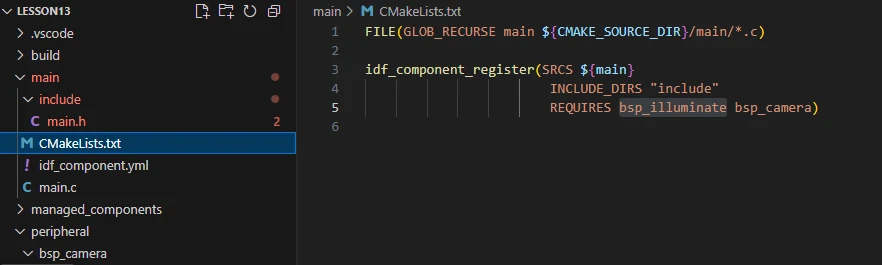
Finally, let's take a look at the "CMakeLists.txt" file in the main directory.
The role of this CMake configuration is as follows:
-
Collect all .c source files in the main/ directory as the source files of the component.
-
Register the main component with the ESP-IDF build system, and declare that it depends on the custom component "bsp_camera" and the custom component "bsp_illuminate".
In this way, during the build process, ESP-IDF will know to build "bsp_camera" and "bsp_illuminate" first, and then build "main".
Note: In the subsequent courses, we will not create a new "CMakeLists.txt" file from scratch. Instead, we will make minor modifications to this existing file to integrate other drivers into the main function.
Complete Code
Kindly click the link below to view the full code implementation.
GitHub Link
Programming Steps
Now that the code is ready, the next step is to flash it to the ESP32-P4 so we can observe the actual behavior.
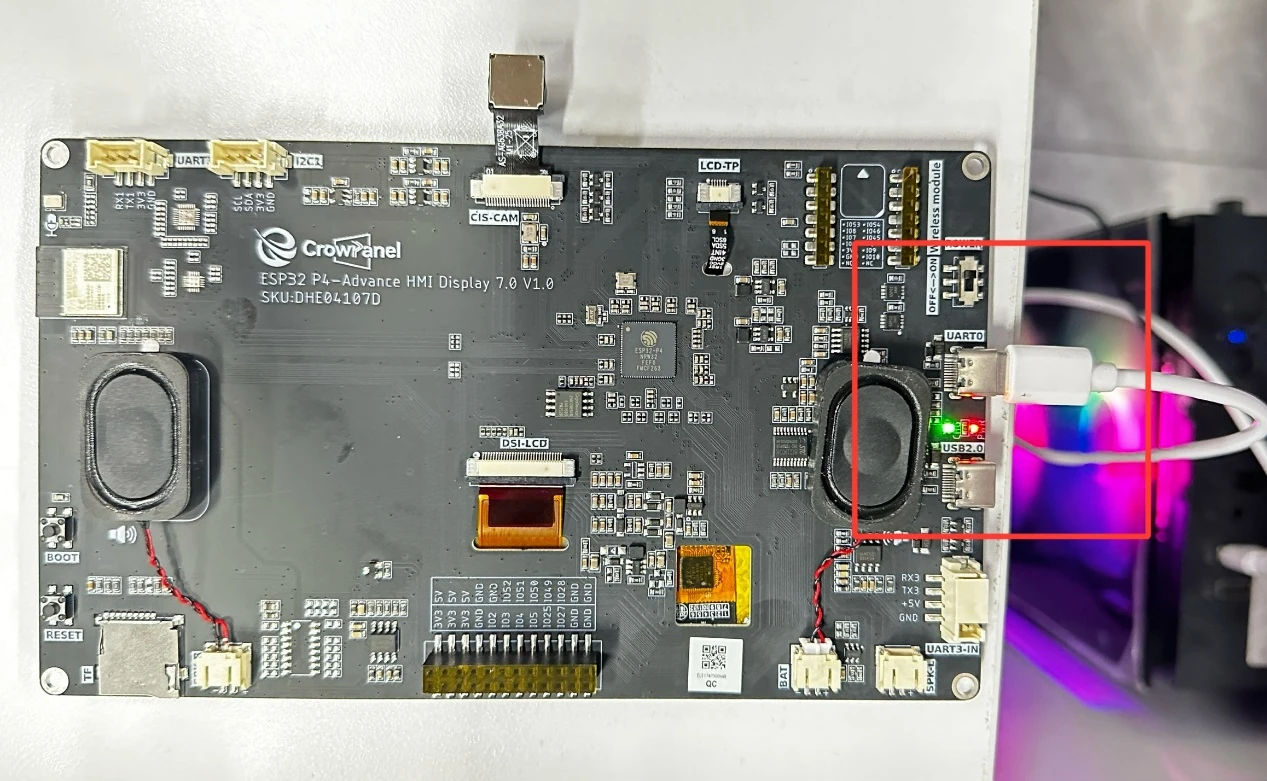
First, connect the Advance-P4 device to your computer via a USB cable.
Before starting the flashing preparation, delete all compiled files to restore the project to its initial "unbuilt" state. (This ensures that subsequent compilations are not affected by your previous build artifacts.)
First, follow the steps from the first section to select the ESP-IDF version, code upload method, serial port number, and target chip correctly.
Next, we need to configure the SDK.
Click the icon shown in the image below.
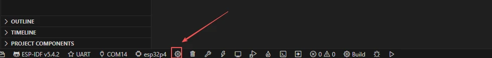
Wait for a short loading period, and then you can proceed with the relevant SDK configuration.
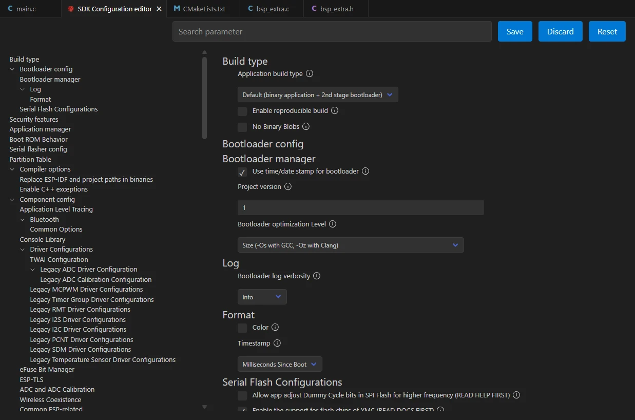
After that, enter "flash" in the search box to find flash-related settings.
(Make sure your flash configuration matches mine exactly.)
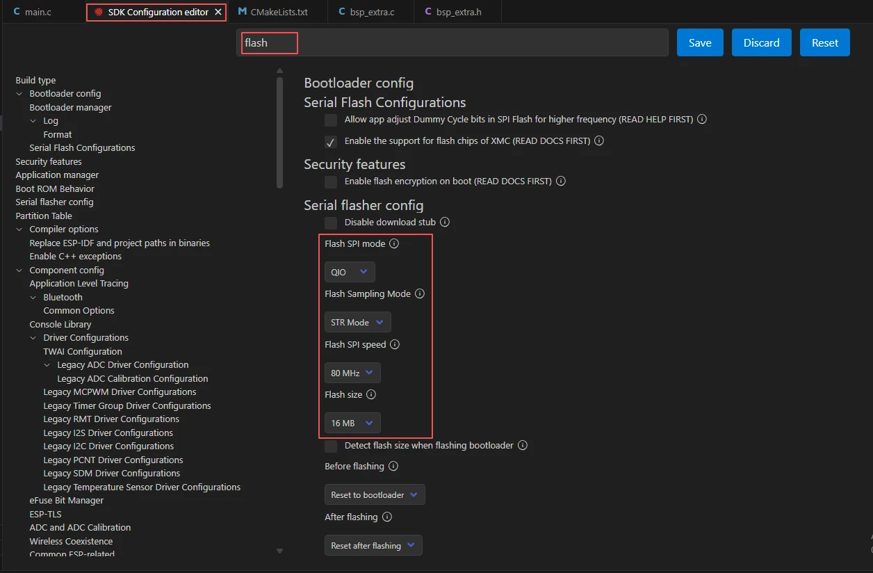
After completing the configuration, remember to save your settings.
Next, we will compile and flash the code (detailed in the first lesson).
Here, we will also introduce a very convenient feature: a single button can execute compilation, upload, and monitor activation in one go.
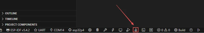
Wait for a moment until the code compilation and upload are completed, and the monitor will open automatically.
At this point, please remember to connect your Advance-P4 with an additional Type-C cable via the USB 2.0 port. This is because the maximum current provided by a computer's USB-A port is generally 500mA, and the Advance-P4 requires a sufficient power supply when using multiple peripherals---especially the screen. (It is recommended to connect it to a charger.)
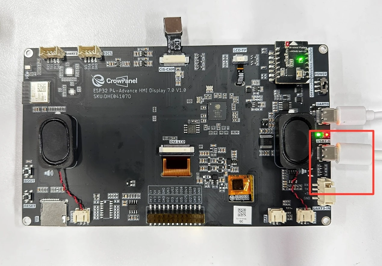
After running the code, you will be able to see the real-time feed from the camera on the Advance-P4 screen.