Lesson14--- SX1262 Wireless Module
Introduction
In this lesson, we will begin exploring the use of wireless modules. Since the SX1262 LoRa module supports both transmission and reception, two Advance-P4 development boards and two SX1262 LoRa communication modules are required.
The objective of this lesson is to implement a case study where, when an SX1262 LoRa module is connected to the wireless module slot of the Advance-P4 board, the transmitting board displays "TX_Hello World:i" on its screen, while the receiving board displays "RX_Hello World:i" along with related LoRa signal information.
Hardware Used in This Lesson
SX1262 Wireless Module on the Advance-P4


Operation Effect Diagram
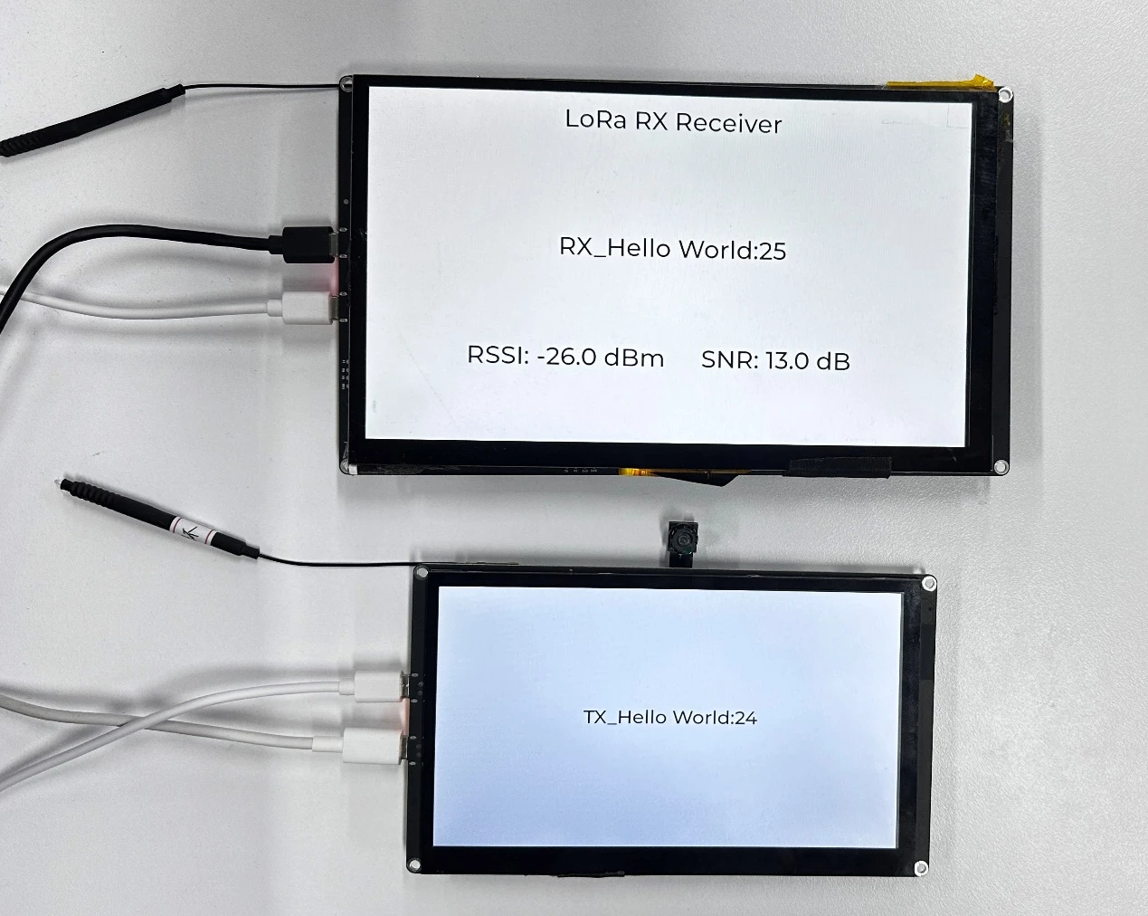
After inserting the SX1262 LoRa modules into both Advance-P4 development boards and running the respective codes, you will observe the following behavior:
On the transmitting Advance-P4 board, the screen will display the message TX_Hello World:i, with the value of i increasing by 1 every second.
Similarly, on the receiving Advance-P4 board, the screen will display RX_Hello World:i whenever a message is received, with i also incrementing by 1 each second. In addition, the screen will show relevant reception signal information such as RSSI and SNR.
Key Explanations
The main focus of this lesson is to learn how to use the wireless module, including how to initialize the SX1262 LoRa module and send or receive data.
In this section, we will introduce a new component called bsp_wireless.
The main functions of this component are as follows:
-
It encodes and modulates the data (such as strings or sensor information) sent from the main controller and transmits it wirelessly.
-
It also receives wireless data packets sent from other devices via LoRa.
-
Through a callback mechanism, it passes the received data back to the upper-layer application.
In addition to the above functions, this component also integrates the experimental functionalities for the remaining three wireless modules: nRF2401, ESP32-C6, and ESP32-H2.
Since the functions of each wireless module in the code are encapsulated within #ifdef and #endif directives, and in this lesson we are using the SX1262 module, we only need to enable the SX1262-related configurations.
How to enable it:
Click SDK Configuration.

Search for "wireless" and open the configuration you are using.

Since in this case we are using the SX1262, only check the option "Enable SX1262 config" and uncheck all the others.
(Enable the one that corresponds to the wireless module you are using.)
After making the changes, don't forget to click Save to apply and store the modifications.

As shown in the figure, we have enabled the SX1262-related configuration, so the other wireless modules are currently disabled and not in use.
Within the bsp_wireless component, you only need to know when to call the provided interfaces that we have written.
Next, let's focus on understanding the bsp_wireless component itself.
First, click the GitHub link below to download the source code for this lesson.
GitHub Link
Then, drag the code for this lesson into VS Code and open the project file.
Once opened, you will see the project structure.
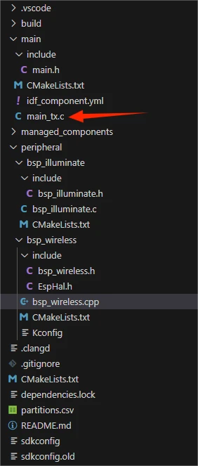
The following section shows the transmitter (TX) side of the project:
The following section shows the receiver (RX) side of the project:
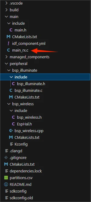
In these two projects, the only difference lies in the main functions: main_tx.c for the transmitter and main_rx.c for the receiver. All other code files are identical. (For convenience, we have prepared both main functions for you to use separately.)
In this lesson's example, a new folder named bsp_wireless has been created under peripheral\. Inside the bsp_wireless\ folder, there is a new include folder and a CMakeLists.txt file.
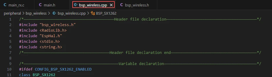
The bsp_wireless folder contains the driver file bsp_wireless.cpp, while the include folder contains the header files bsp_wireless.h and EspHal.h.
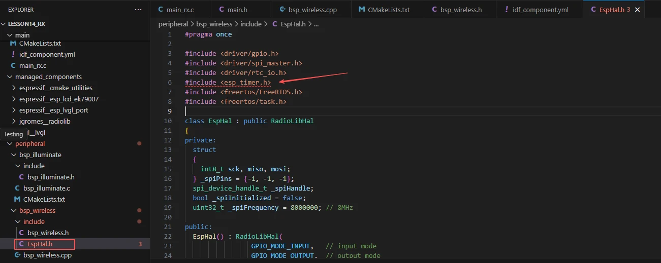
The purpose of EspHal.h is to convert C code from ESP-IDF into the Arduino-style C++ code required by the RadioLib component library.
The CMakeLists.txt file integrates the driver into the build system, allowing the project to use the LoRa module transmission and reception functions implemented in bsp_wireless.cpp.
Additionally, there is bsp_illuminate, our familiar component from previous lessons, which we use to light up the screen and render text using LVGL.
SX1262 LoRa Code
The SX1262 LoRa transmission and reception code consists of two files: bsp_wireless.cpp and bsp_wireless.h.
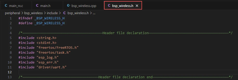
Next, we will first analyze the SX1262-related code in bsp_wireless.h.
bsp_wireless.h is the header file for the SX1262 LoRa wireless module. Its main purposes are:
To declare the functions, macros, and variables implemented in bsp_wireless.cpp for external use.
To allow other .c files to simply #include "bsp_wireless.h" in order to call this module.
In other words, it serves as the interface layer, exposing which functions and constants can be used externally while hiding the internal details of the module.
Any libraries required for this component are included in both bsp_wireless.h and bsp_wireless.cpp.
Since the function implementation in bsp_wireless.cpp uses the function encapsulation from EspHal.h, the reference to the header file needs to be placed in the .cpp file.
Take #include <RadioLib.h> as an example; this is a library under the network component.

This requires us to specify the version of jgromes/radiolib in the idf_component.yml file located in the main folder.
Since this is an official library, we need to rely on it to implement the SX1262 LoRa wireless transmission or reception functionality on our Advance-P4.

These three components, which we discussed earlier, are used in the bsp_illuminate component to light up the screen and render information on the interface using LVGL.
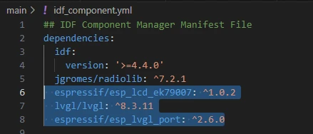
During the subsequent compilation process, the project will automatically download the following library versions:
-
jgromes/Radiolib version 7.2.1
-
espressif/esp_lcd_ek79007 version 1.0.2
-
lvgl version 8.3.11
-
espressif/esp_lvgl_port version 2.6.0
Once downloaded, these online components will be stored in the managed_components folder. (This is automatically generated after specifying the version numbers.)
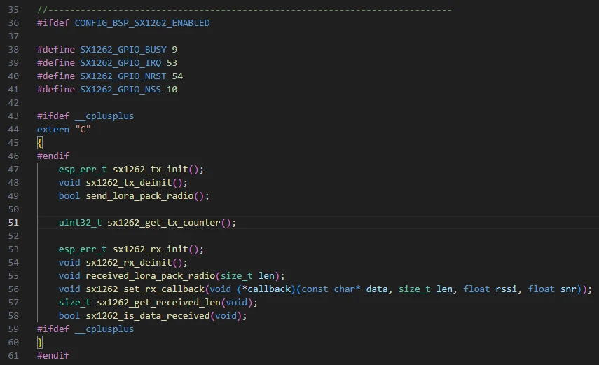
Returning to bsp_wireless.h,here we declare the pins used by the wireless module.

The pin assignments should not be modified, otherwise the wireless module will not work due to incorrect connections.
Next, we declare the variables and functions that we will use. The actual implementation of these functions is in bsp_wireless.cpp.
By placing them all in bsp_wireless.h, it becomes easier to call and manage them. (We will explore their specific functionality when we look at bsp_wireless.cpp.)
Next, let's take a look at bsp_wireless.cpp to understand the specific function of each function.
The bsp_wireless component implements LoRa data transmission and reception, communicates with the main controller via the SPI interface, and handles the sending and receiving at the wireless data link layer.
Here, we won't go into the detailed code. Instead, we will explain the purpose of each function and when to call them.
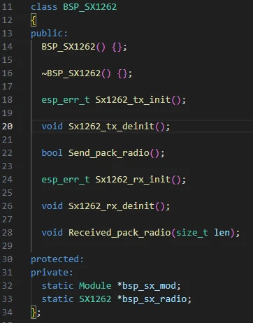
BSP_SX1262 Class:
This indicates that:
-
It is a C++ wrapper class for operating the SX1262 module.
-
It mainly provides functions for initialization, de-initialization, and data transmission/reception.
-
All hardware operations are performed based on the RadioLib library.
-
bsp_sx_mod and bsp_sx_radio are object pointers in memory for the SX1262 module (statically shared).
Defines the core global variables required by the SX1262 LoRa module driver, used to manage the module instance, status, and data callbacks:
-
lora_hal is the low-level SPI hardware abstraction layer object, responsible for SPI communication.
-
bsp_sx_mod and bsp_sx_radio point to the generic RadioLib module object and the SX1262 module object, respectively. They encapsulate the specific hardware pins and transmission/reception interfaces. These objects are created during module initialization (e.g., Sx1262_tx_init() or Sx1262_rx_init()) and released or set to standby during de-initialization.
-
lora_transmissionState records the status code of the last transmission operation for debugging and error handling.
-
lora_transmittedFlag is the transmission completion flag, set by the transmission interrupt callback set_sx1262_tx_flag(), indicating that the module is ready to send a new data packet.
-
lora_receivedFlag is the reception completion flag, set by the reception interrupt callback set_sx1262_rx_flag(), indicating that new data is available to read.
-
lora_received_len stores the length of the most recently received data.
-
rx_data_callback is a function pointer that allows the upper layer to register a callback. When the SX1262 receives data, this callback is automatically triggered, passing the received data, its length, RSSI, and SNR information to the upper-level processing.

Sx1262_tx_init():
The function Sx1262_tx_init() in the BSP_SX1262 class is used to initialize the SX1262 module for data transmission.
-
The function first uses lora_hal to configure the SPI pins (RADIO_GPIO_CLK, RADIO_GPIO_MISO, RADIO_GPIO_MOSI) and the SPI clock frequency (8 MHz), then calls spiBegin() to start SPI communication, providing the module with a low-level communication interface.
-
Next, it creates a Module object bsp_sx_mod to encapsulate the SX1262 hardware pins (NSS, IRQ, NRST, BUSY) and uses this module object to create the SX1262 instance bsp_sx_radio. By calling begin(), it configures the LoRa parameters (915 MHz frequency, 125 kHz bandwidth, spreading factor 7, coding rate 4/7, sync word, 22 dBm power, pre-gain 8, LNA 1.6, etc.), completing the module initialization.
-
Finally, it calls setPacketSentAction(set_sx1262_tx_flag) to register the transmission completion callback, which sets lora_transmittedFlag whenever a data packet is sent, indicating that the module is ready to send the next packet.
This function is usually called at system startup or before starting LoRa data transmission. It only needs to be initialized once to ensure the module is in a transmittable state, after which data packets can be sent periodically using Send_pack_radio().
If two LoRa modules are used for transmission and reception, they must operate on the same frequency band.
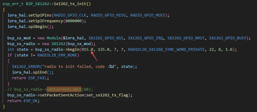
In bsp_sx_radio->begin(), the 915.0 MHz represents the operating center frequency of the SX1262. This can be changed according to the LoRa frequency regulations of different regions:
-
China commonly uses 433 MHz or 470--510 MHz
-
Europe uses 868 MHz
-
The United States and Australia use 915 MHz
-
Japan uses 923 MHz
When changing the frequency, the transmitter and receiver must match, otherwise communication will fail. Additionally, ensure that the selected frequency falls within the legally allowed ISM band for that region.
Parameters such as bandwidth and spreading factor can generally remain unchanged, although some frequency bands may have officially recommended values.
Send_pack_radio:
The function Send_pack_radio() in the BSP_SX1262 class is the core function for sending LoRa data packets.
-
It first checks the transmission completion flag lora_transmittedFlag. If it is true, it indicates that the previous packet has been sent and the module is ready to send new data.
-
If so, the flag is reset to false to prevent duplicate transmissions. The function then checks lora_transmissionState to determine whether the previous transmission was successful and prints the corresponding log.
-
Next, it calls bsp_sx_radio->finishTransmit() to complete any remaining operations from the previous transmission, ensuring the module is ready for use. The transmission counter sx1262_tx_counter is incremented, and a text message with the counter is formatted and stored in the static buffer text.
-
The function then calculates the message length and calls bsp_sx_radio->startTransmit() to initiate the transmission of the new data packet. It also updates lora_transmissionState to record the status of this transmission. If the transmission fails to start, an error message is printed.
-
Finally, the function returns true if the transmission event has been handled, or false if the module is not yet ready to send.
This function is usually called periodically in the main loop or task scheduler to poll and send LoRa data packets, and it must ensure that the previous transmission is complete before sending a new packet.
sx1262_get_tx_counter()
This is a C-style interface used to obtain the value of the SX1262 module's transmitted packet counter sx1262_tx_counter. The function simply returns the global static variable sx1262_tx_counter and does not modify any state. It is typically used in applications to query the number of packets sent, for example, for debugging, statistics, or displaying the transmission count. It can be called at any time and does not depend on the transmission or reception status.
sx1262_tx_init()
This is a C-style wrapper interface for initializing the SX1262 transmission functionality. Inside the function, a BSP_SX1262 object is created, and its method Sx1262_tx_init() is called to complete the LoRa module SPI configuration, module object creation, parameter initialization, and registration of the transmission completion callback. The function returns ESP_OK if initialization is successful, or ESP_FAIL if it fails. This function is typically called once at system startup or before starting data transmission to ensure that the module is in a ready-to-transmit state.
sx1262_tx_deinit()
This is a C-style de-initialization interface for the SX1262 transmission function. Inside the function, a BSP_SX1262 object is created, and its method Sx1262_tx_deinit() is called to shut down the transmission functionality. During de-initialization, it calls finishTransmit() to complete any ongoing transmission, clears the transmission callback, switches the module to standby mode, and closes the SPI interface. This function is generally called when the system is shutting down, the module no longer needs to send data, or it enters low-power mode, releasing resources and ensuring the module safely stops.
send_lora_pack_radio()
This is a C-style interface used to trigger the SX1262 to send a data packet. Inside the function, a BSP_SX1262 object is created, and its method Send_pack_radio() is called. It polls the transmission completion flag lora_transmittedFlag and, when ready, generates a data packet and starts transmission. The function returns true if the transmission event has been handled, or false if the module is not yet ready. It is usually called periodically in the main loop or task scheduler to achieve continuous or scheduled data transmission.
set_sx1262_rx_flag()
This is a static internal function used as the callback for SX1262 reception completion. Inside the function, it sets the global reception flag lora_receivedFlag to true, notifying the system that a new data packet has been received.
It is not called directly. Instead, it is registered by calling bsp_sx_radio->setPacketReceivedAction(set_sx1262_rx_flag), and the SX1262 hardware automatically triggers it each time a reception is completed, driving the data reception processing logic.
Sx1262_rx_init()
The function Sx1262_rx_init() in the BSP_SX1262 class is used to initialize the SX1262 module for reception.
-
The function first uses lora_hal to configure the SPI pins (RADIO_GPIO_CLK, RADIO_GPIO_MISO, RADIO_GPIO_MOSI) and the SPI clock frequency (8 MHz), then calls spiBegin() to start SPI communication, providing a low-level interface for the SX1262.
-
Next, it creates a Module object bsp_sx_mod and an SX1262 object bsp_sx_radio to encapsulate the hardware pins and transmission/reception interfaces. It then calls begin() to configure the LoRa parameters (915 MHz frequency, 125 kHz bandwidth, spreading factor 7, coding rate 4/7, sync word, 22 dBm power, etc.), completing module initialization. If initialization fails, an error is printed and the function returns a failure status.
-
It then registers the reception completion callback via setPacketReceivedAction(set_sx1262_rx_flag), so that the module automatically sets lora_receivedFlag whenever a packet is received.
-
The function calls setRxBoostedGainMode(true) to enable boosted gain mode for improved reception sensitivity, then calls startReceive() to start reception mode. If starting reception fails, it prints an error and returns failure.
This function is usually called once at system startup or before starting LoRa data reception to ensure the module is in a receivable state, after which received data can be processed via polling or callback.
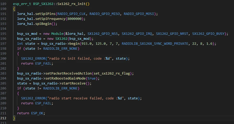
Here, we are initializing the receiver module. Similarly, by keeping the frequency band at 915 MHz, the module can successfully receive the data sent from the transmitter.
Received_pack_radio:
The function Received_pack_radio(size_t len) in the BSP_SX1262 class is the core function for handling received LoRa data packets.
-
The function first checks the reception flag lora_receivedFlag. If it is true, it indicates that a new data packet has arrived. The flag is then reset to false to prevent duplicate processing.
-
It then obtains the actual length of the received data via bsp_sx_radio->getPacketLength(). If a valid length is returned, it is used; otherwise, the externally provided len serves as a fallback.
-
Next, a buffer data[255] is defined, and bsp_sx_radio->readData() is called to read the received data into the buffer. If reading succeeds, the function prints the received data, RSSI (Received Signal Strength), SNR (Signal-to-Noise Ratio), and frequency offset. If a callback function rx_data_callback has been registered, it passes the data, length, and signal parameters to the upper-level application for processing.
This function is usually called periodically in the main loop or tasks. It executes after the SX1262 reception interrupt sets lora_receivedFlag, allowing the upper-level application to retrieve and process received packets promptly and reliably.

sx1262_rx_init()
This is a C-style interface used to initialize the SX1262 module's reception function. Inside the function, a BSP_SX1262 object is created, and its member function Sx1262_rx_init() is called to complete SPI configuration, module initialization, parameter setup, registration of the reception callback, and starting reception mode. The function returns ESP_OK if initialization succeeds, or ESP_FAIL if it fails. This function is typically called once at system startup or before starting LoRa data reception to ensure the module is in a ready-to-receive state.
sx1262_rx_deinit()
This is a C-style de-initialization interface for the SX1262 reception function. Inside the function, a BSP_SX1262 object is created, and its method Sx1262_rx_deinit() is called to shut down the reception functionality. The de-initialization process includes clearing the reception callback, switching the module to standby mode, delaying to ensure safe shutdown, and closing the SPI interface. This function is generally called when the system is shutting down, the module no longer needs to receive data, or it enters low-power mode.
received_lora_pack_radio(size_t len)
This is a C-style interface used to handle received LoRa data packets. Inside the function, a BSP_SX1262 object is created, and its method Received_pack_radio(len) is called. The function processes the data by checking the reception flag, reading the data, printing logs, and invoking the upper-layer callback function.
This function is generally called periodically in the main loop or tasks and executes after lora_receivedFlag is set, ensuring that the upper-level application can timely retrieve and handle received data packets.
sx1262_set_rx_callback(void (*callback)(const char* data, size_t len, float rssi, float snr))
This function is used to register the upper-layer callback rx_data_callback. When the SX1262 module receives a data packet, this callback is automatically triggered, passing the data, length, RSSI, and SNR information to the upper-layer application. This function is typically called once after initializing the reception functionality to bind the data processing logic.
sx1262_get_received_len()
This is a query interface that returns the length of the most recently received data lora_received_len. Internally, the function simply returns the static variable without modifying any state. It is usually called when processing received data or performing debug/statistics, to obtain the actual length of the received packet.
sx1262_is_data_received()
This is a status query interface that returns the reception flag lora_receivedFlag, used to determine whether a new data packet has arrived. The function simply returns the status of the global variable without modifying it. It is typically polled in the main loop or tasks to decide whether to call received_lora_pack_radio() to process new data.
That concludes the introduction to the bsp_wireless component. You only need to know how to call these interfaces.
When calling these functions, you also need to configure the CMakeLists.txt file in the bsp_wireless folder. This file, located in the bsp_wireless directory, mainly tells the ESP-IDF build system (CMake) how to compile and register the bsp_wireless component.
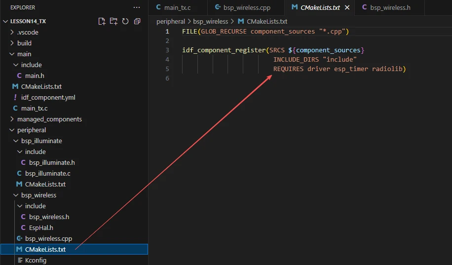
The reason driver, esp_timer, and RadioLib are included here is that we call them in bsp_wireless.h and bsp_wireless.cpp. Other libraries are system libraries and do not need to be explicitly added.


As well as the esp_timer used in the EspHal.h file.
Main Function
The main folder is the core directory for program execution and contains the main executable file main_tx.c.
Add the main folder to the build system's CMakeLists.txt file.
This is the entry file for the entire application. In ESP-IDF, there is no int main(); execution starts from void app_main(void).
Let's first go through the transmitter main function file main_tx.c to see how it calls interfaces to send LoRa messages.
When the program runs, the general flow is as follows:
After the system starts, app_main() first calls Hardware_Init() to initialize the hardware, including the LDO power channels (ldo3, ldo4), the LCD display and LVGL library, and the SX1262 LoRa transmission module, ensuring all hardware resources are ready.
-
Then, lvgl_show_counter_label_init() is called to create an LVGL label for displaying the transmission count, centered on the screen. After initialization, the system enters the task scheduling stage.
-
The system creates two FreeRTOS tasks:
-
ui_counter_task reads the SX1262 transmission counter every second, updates the display via LVGL, and prints logs.
-
lora_tx_task calls send_lora_pack_radio() every second to send LoRa data packets and prints error messages if transmission fails.
-
The two tasks use vTaskDelayUntil() to ensure synchronized execution on a fixed 1-second cycle, enabling coordinated screen display and wireless transmission, achieving the complete process of sending LoRa messages every second and dynamically showing "TX_Hello World:count" on the screen.
Next, let's go through the main code in main_tx.c.

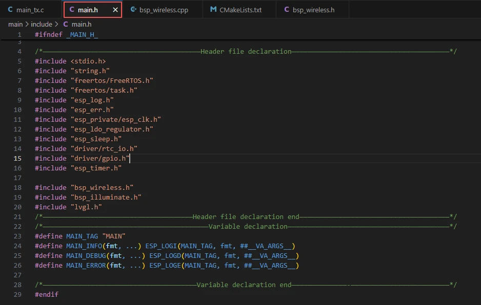
It includes the custom main header file main.h, which typically contains log macros, peripheral initialization declarations, and headers for other interfaces that need to be used.
Below is the content of main.h:
Let's continue looking at the content of main_tx.c.
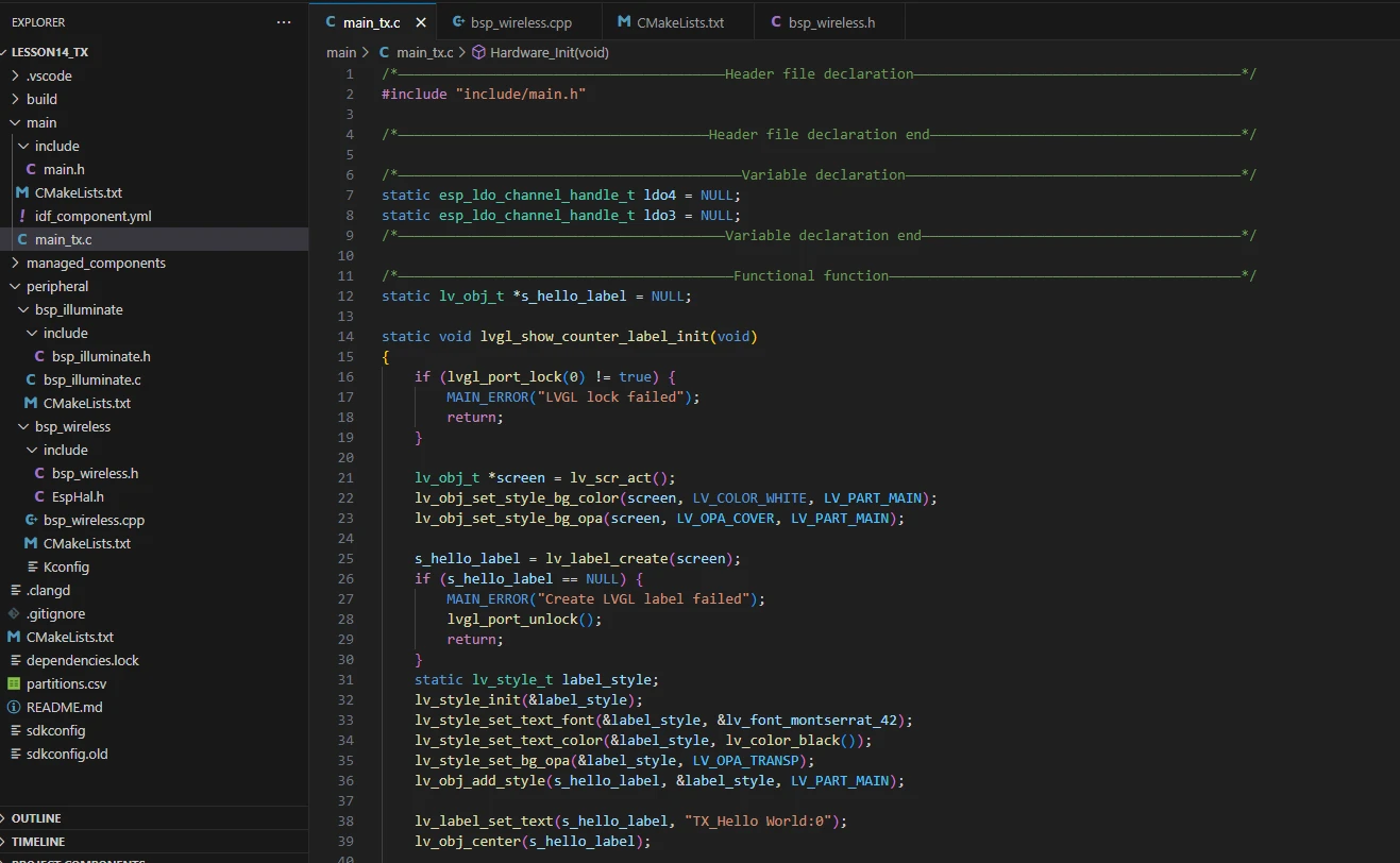
lvgl_show_counter_label_init:
The function lvgl_show_counter_label_init() initializes the counter label in the LVGL display interface, used to show the LoRa transmission count.
-
The function first calls lvgl_port_lock(0) to acquire the LVGL operation lock, ensuring safe access to LVGL in a multi-task environment. If locking fails, it prints an error and returns.
-
It then gets the current active screen object via lv_scr_act() and sets the screen background to white, fully covering the display.
-
Next, it creates a label object s_hello_label. If creation fails, an error is printed, the lock is released, and the function returns.
-
It then creates and initializes a style label_style for the label, setting the font to Montserrat size 42, text color to black, and background to transparent, and applies the style to the label.
-
Using lv_label_set_text(), the initial text is set to "TX_Hello World:0", and lv_obj_center() centers the label on the screen.
-
Finally, lvgl_port_unlock() is called to release the LVGL lock, allowing other tasks to safely operate on LVGL.
If you want to change the LVGL font size, you need to go into the SDK configuration and enable the desired font.
Steps:
Click on the SDK Configuration option.
Search for "font" and select the font size you want to use.
After making changes, remember to save.

ui_counter_task:
The function ui_counter_task() is a FreeRTOS task that updates the LoRa transmission count label on the LVGL display every second.
-
Inside the function, a character array text[48] is defined to store the formatted display text. The current system tick count is obtained via xTaskGetTickCount() as the task's initial wake time last_wake_time, and the task period frequency is set to 1000 milliseconds.
-
The task enters an infinite loop. In each iteration, it calls sx1262_get_tx_counter() to get the current number of LoRa packets sent, then formats the string as "TX_Hello World:count" using snprintf.
-
It then attempts to acquire the LVGL operation lock. If successful and the label object s_hello_label is valid, it updates the label text and releases the lock, ensuring safe LVGL access in a multi-task environment.
-
Next, it prints the current transmission information using MAIN_INFO.
-
Finally, vTaskDelayUntil() is called with absolute timing to ensure each loop executes precisely every one second.
Overall, this task continuously refreshes the display with the LoRa transmission count while logging, providing real-time visual feedback.
Hardware_Init:
The function Hardware_Init() is used to initialize hardware modules when the program starts, ensuring that all parts of the system work properly.
-
First, it calls esp_ldo_acquire_channel() to acquire the LDO3 (2.5V) and LDO4 (3.3V) power channels. If acquisition fails, it calls init_or_halt(), repeatedly waiting and printing error messages to ensure stable power.
-
Next, it calls display_init() to initialize the LCD hardware and the LVGL graphics library, which must be done before turning on the backlight, otherwise the display may behave abnormally.
-
Then, it calls set_lcd_blight(100) to turn on the LCD backlight and set the brightness to maximum 100, using init_or_halt() to check for errors.
-
Finally, it calls sx1262_tx_init() to initialize the LoRa transmission module. If initialization fails, it is also handled via init_or_halt().
Overall, this function provides a reliable hardware environment for screen display, backlight, and the wireless communication module, ensuring that subsequent program functionality runs smoothly. It is typically called in app_main() during system startup.
lora_tx_task:
The function "lora_tx_task()" is a FreeRTOS task used to periodically send data packets through the LoRa module.
-
The function first obtains the current system tick count using "xTaskGetTickCount()" as the start time of the task, and sets the transmission period to 1000 milliseconds (1 second).
-
In an infinite loop, it calls "send_lora_pack_radio()" to attempt sending a LoRa data packet. It determines whether the transmission is successful through the return value, and if the transmission fails, it prints an error log using "MAIN_ERROR".
-
Finally, it uses "vTaskDelayUntil()" to delay according to absolute time, ensuring that each loop sends data at an accurate interval of 1 second, thus achieving timed and stable wireless data transmission.
This task is usually created after the system starts and runs continuously to continuously broadcast messages to the receiving end.
app_main:
The function "app_main()" is the entry point of the entire program. After the system starts, it first prints the "LoRa TX" log to indicate entering the main process.
Subsequently, it calls "Hardware_Init()" to complete hardware initialization, including the initialization of LDO power supply, LCD display, and LoRa module.
Then, it invokes "lvgl_show_counter_label_init()" to create and display a text label for counting on the LCD.
After that, it uses "xTaskCreatePinnedToCore()" to create two FreeRTOS tasks: "ui_counter_task" is used to update the LVGL label displaying the transmission count every second, and "lora_tx_task" is used to send LoRa data packets every second. Both tasks have the same priority to maintain synchronization.
Finally, it prints a log indicating that the task creation is completed and synchronous transmission starts.

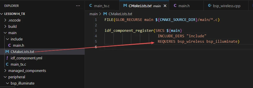
Finally, let's take a look at the "CMakeLists.txt" file in the main directory.
The role of this CMake configuration is as follows:
-
Collect all .c source files in the main/ directory as the source files of the component.
-
Register the main component to the ESP-IDF build system, and declare that it depends on the custom component bsp_wireless and the custom component bsp_illuminate.
In this way, during the build process, ESP-IDF knows to build bsp_wireless and bsp_illuminate first, and then build main.
The above is the main function code for the transmitter. Next, let's take a look at the main function code for the receiver.
This section of code defines several static global variables that are crucial in the LoRa reception program:
-
First, static esp_ldo_channel_handle_t ldo4 = NULL; is used to store the handle of ESP32's internal LDO channel 4. This channel is responsible for outputting 3.3V voltage to power peripheral devices such as the display screen or wireless module.
-
Next, static esp_ldo_channel_handle_t ldo3 = NULL; defines the handle of LDO channel 3. It outputs 2.5V voltage and is often used to power low-voltage modules (e.g., LoRa RF chips).
-
Then, static lv_obj_t *s_rx_label = NULL; defines a pointer to an LVGL label object, which is used to display the received LoRa data content on the screen.
-
static lv_obj_t *s_rssi_label = NULL; is an interface label used to display the RSSI (signal strength) value, allowing users to know the strength of the received signal.
-
static lv_obj_t *s_snr_label = NULL; defines another LVGL label, which is used to display the SNR (signal-to-noise ratio) value to help determine the quality of the received signal.
-
Finally, static uint32_t rx_packet_count = 0; is a counting variable used to record the number of received LoRa data packets. It increments by 1 each time data is received, enabling real-time display of the reception count and system working status on the interface.

rx_data_callback:
The function rx_data_callback() is the core callback function of the entire LoRa receiving program. It is automatically triggered and executed when the wireless module successfully receives a frame of LoRa data, and is used to process the reception event and update the interface display in real time.
-
First, the function increments the reception count by rx_packet_count++ to record the arrival of a new data packet.
-
Then, it calls lvgl_port_lock(0) to acquire a lock, ensuring safe operation of the LVGL graphical interface in a multi-tasking environment.
-
If the lock is successfully acquired, it updates three interface elements in sequence: first, it checks whether s_rx_label exists; if it does, it uses snprintf() to format the string "RX_Hello World:\<Number>", and updates the reception count displayed on the screen via lv_label_set_text().
-
Next, it updates the signal strength label s_rssi_label to display the current RSSI value (Received Signal Strength Indicator, in dBm) on the interface.
-
Then, it updates the signal-to-noise ratio label s_snr_label to display the SNR value (Signal-to-Noise Ratio, in dB) of the current received signal, reflecting the signal quality.
-
After the interface update is completed, the function calls lvgl_port_unlock() to release the lock.
-
Finally, it prints a log via MAIN_INFO(), outputting the serial number of the data received this time, the RSSI, and the SNR value to the console, facilitating debugging and system status monitoring.
Overall, the function's role is to synchronously update the screen and logs each time a LoRa data packet arrives, intuitively reflecting the system's real-time reception status and signal quality. It is a key link for data visualization and operation monitoring in the application.
lvgl_show_rx_interface_init:
The function lvgl_show_rx_interface_init() is the initialization function for the LoRa receiver interface. It is responsible for creating and beautifying the graphical interface used to display LoRa reception status before system startup or the beginning of the reception task.
The function first acquires the LVGL graphics lock via lvgl_port_lock(0), ensuring safe operation of interface objects in a multi-threaded environment.
Then it calls lv_scr_act() to obtain the currently active screen object and sets the screen background to white with full opacity, providing a clear display background.
Next, it defines and initializes a general style info_style, uniformly setting the font size, text color (black), and transparent background, which is shared by the RSSI and SNR labels.
Subsequently, it creates four main interface elements in sequence:
-
Title label title_label --- displays the title "LoRa RX Receiver", using a large font style and centered at the top of the screen to identify the interface function.
-
Received content label s_rx_label --- shows the currently received LoRa message content, initially set to "RX_Hello World:0", positioned slightly above the center of the screen.
-
Signal strength label s_rssi_label --- displays the RSSI (Received Signal Strength), initially "RSSI: -- dBm", placed at the lower left of the interface.
-
Signal-to-noise ratio label s_snr_label --- displays the SNR (Signal-to-Noise Ratio), initially "SNR: -- dB", positioned at the lower right, symmetrical to the RSSI label.
All labels use predefined styles to ensure consistent fonts and colors. After creating the interface, the function calls lvgl_port_unlock() to release the lock, allowing other tasks to access the LVGL system.
Overall, the function initializes the visual interface for the LoRa receiver, providing a clear UI layout for real-time display of received data (such as message content, signal strength, and SNR). It serves as the core initialization function for the graphical display in the program.
lora_rx_task:
The function lora_rx_task() is the LoRa reception task, responsible for continuously detecting and processing data packets received from the SX1262 module during system operation.
-
The function runs in a dedicated FreeRTOS task, using an infinite loop to continuously listen for LoRa signals.
-
Inside the loop, it first calls sx1262_is_data_received() to check whether a new data packet has arrived.
-
If a reception event is detected, it calls sx1262_get_received_len() to obtain the length of the received data, then passes this length as a parameter to received_lora_pack_radio(len), which handles data parsing and display logic (e.g., updating the received content, RSSI, and SNR on the interface).
-
If no data is currently received, the program delays 10 ms using vTaskDelay(10 / portTICK_PERIOD_MS), reducing CPU usage and maintaining balanced task execution.
Overall, this function maintains the real-time listening mechanism for the LoRa receiver, ensuring that any incoming wireless data is captured and processed promptly. It is the core background task responsible for data reception and event handling in the LoRa communication system.
app_main:
The function app_main() serves as the main entry function of the entire LoRa receiver program, responsible for completing core startup tasks such as system initialization, UI interface configuration, and task creation.
-
At the beginning of the function, it outputs a startup log via MAIN_INFO("---------- LoRa RX ----------") to indicate that the system has entered LoRa reception mode.
-
It then calls Hardware_Init() to initialize all underlying hardware resources, including power management, SPI communication interfaces, and LoRa modules, laying the foundation for subsequent communication.
-
Subsequently, it executes lvgl_show_rx_interface_init() to create and initialize the LVGL graphical interface, which is used to display real-time information such as received messages, RSSI, and SNR on the screen.
-
Next, it calls sx1262_set_rx_callback(rx_data_callback) to register a data reception callback function. When the LoRa module receives data, the system will automatically trigger this callback to process and display the information.
-
Finally, it creates an independent task lora_rx_task under FreeRTOS through xTaskCreatePinnedToCore(), which is pinned to core 1 to continuously monitor LoRa signals, enabling asynchronous data reception and real-time response.
This concludes our explanation of the main function code for both the receiver and transmitter ends.
Complete Code
Kindly click the link below to view the full code implementation.
GitHub Link
Programming Steps
Now that the code is ready, the next step is to flash it onto the ESP32-P4 so we can observe the actual operation.
First, connect the Advance-P4 device to your computer using a USB cable.

Before starting the flashing preparation, delete all files generated during compilation to restore the project to its initial "unbuilt" state. This ensures that subsequent compilations are not affected by your previous build results.

Next, follow the steps from the first section to select the ESP-IDF version, code upload method, serial port number, and target chip correctly.
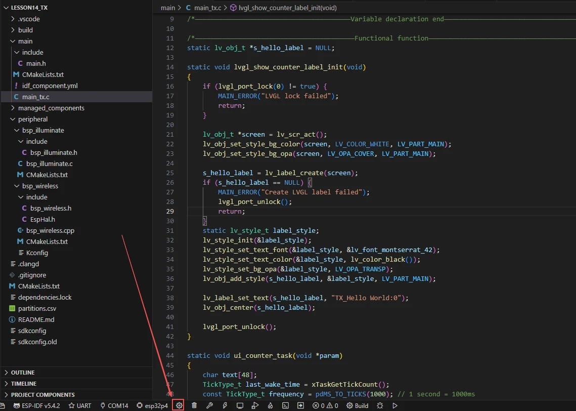
Then, we need to configure the SDK.
Click on the icon shown in the figure below.
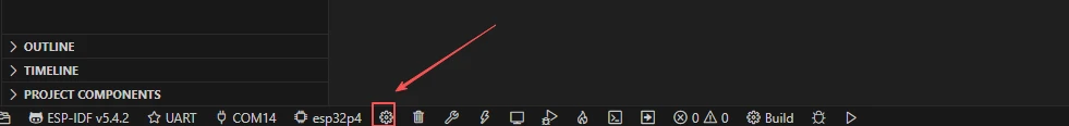
Wait for a short loading period, and then you can proceed with the relevant SDK configuration.
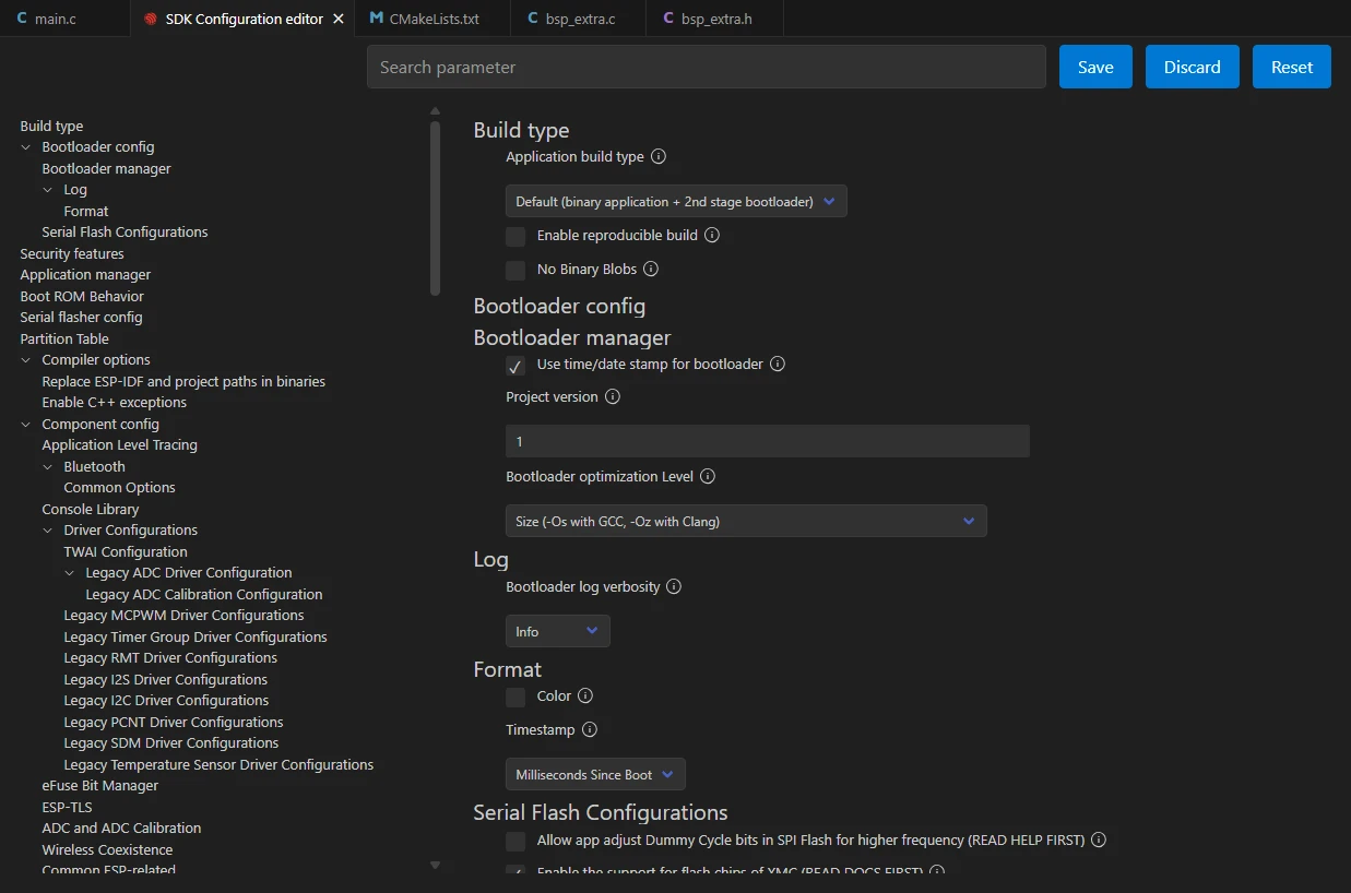
Then, type "flash" into the search box.
(Ensure your flash configuration matches mine.)

After completing the configuration, remember to save your settings.
Next, we will compile and flash the code (detailed in the first lesson).
Here, we'd like to share a very convenient feature with you: a single button can execute compilation, uploading, and serial monitor opening in one go.
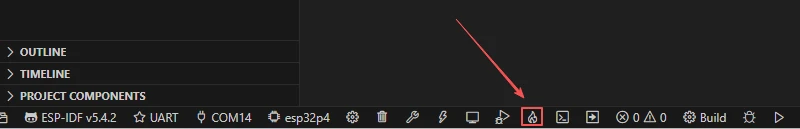
After waiting for a moment, the code will finish compiling and uploading, and the serial monitor will open automatically.
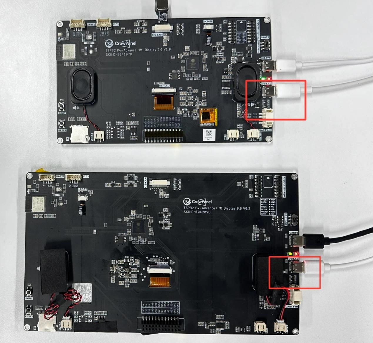
At this point, remember to connect your Advance-P4 using an additional Type-C cable via the USB 2.0 interface. This is because the maximum current provided by a computer's USB-A port is generally 500mA, while the Advance-P4 requires a sufficient power supply when using multiple peripherals---especially a display. (Using a dedicated charger is recommended.)
Insert the LoRa module SX1262 into the two Advance-P4 development boards respectively.
After inserting the modules and running the code on each board respectively, you will be able to see the LoRa module transmitting "TX_Hello World:i" on the screen of the transmitter-side Advance-P4, with the value of "i" increasing by 1 every second.
Similarly, on the screen of the receiver-side Advance-P4, you can see the LoRa module receiving "RX_Hello World:i". When a message is received, "i" also increases by 1 every second. At the same time, you can also view the relevant received signal status: RSSI and SNR.
-
RSSI (Received Signal Strength Indicator) indicates the strength of the received signal, with the unit of dBm (decibel-milliwatts). A larger value (closer to 0) means a stronger signal; a smaller value (e.g., -120 dBm) means a weaker signal. It can reflect the distance between the receiver and the transmitter, as well as the stability of the communication link.
-
SNR (Signal-to-Noise Ratio) represents the ratio of the signal to noise, also with the unit of dB (decibels). A higher SNR indicates better signal quality and lower noise; an excessively low SNR (even negative values) means the signal is severely interfered with by noise.