Lesson15--- nRF2401 Wireless RF Module
Introduction
In this lesson, we will start using another wireless module. Since we will implement the transmission and reception functions of the nRF2401 module, two Advance-P4 development boards and two nRF2401 wireless RF (Radio Frequency) communication modules are required.
The project to be completed in this lesson is as follows: When the nRF2401 module is connected to the wireless module slot of the Advance-P4, the transmitter-side Advance-P4 screen will display "NRF24_TX_Hello World:i", and the corresponding receiver-side Advance-P4 screen will display "NRF24_RX_Hello World:i". The value of "i" on the receiver will only increment by 1 when it receives the signal from the transmitter.
Hardware Used in This Lesson
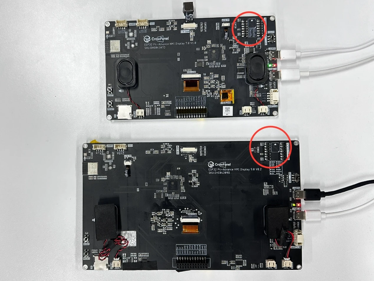
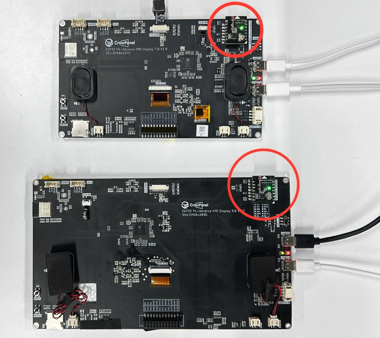
nRF2401 Wireless Module on Advance-P4
Operation Effect Diagram
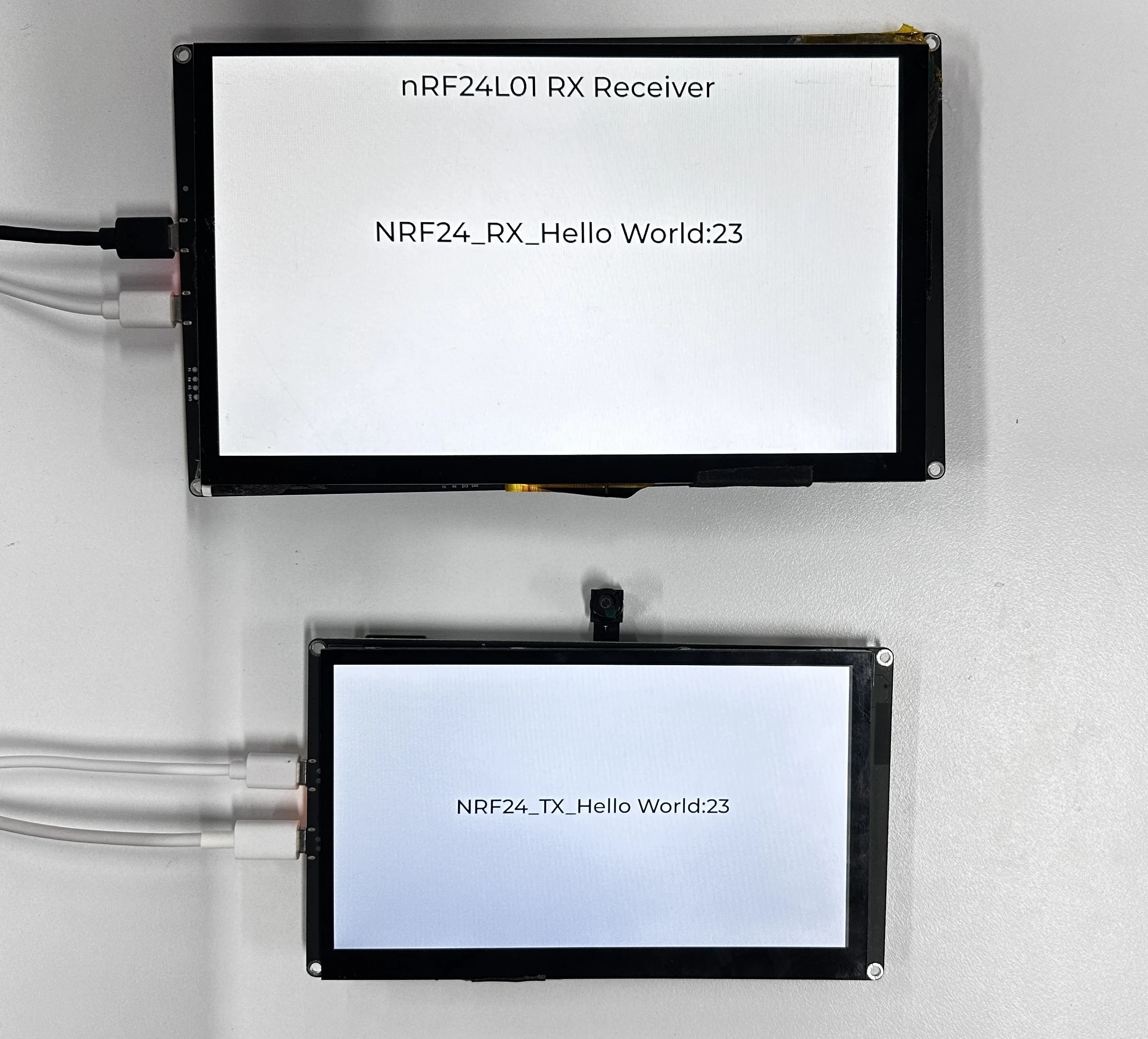
After inserting the nRF2401 wireless RF modules into the two Advance-P4 development boards and running the code on each respectively, you will be able to see the nRF2401 module transmitting "NRF24_TX_Hello World:i" on the screen of the transmitter-side Advance-P4, with the value of "i" increasing by 1 every second.
Similarly, on the screen of the receiver-side Advance-P4, you can see the nRF2401 module receiving "NRF24_RX_Hello World:i". When a message is received, "i" also increases by 1 every second.
Key Explanations
The focus of this lesson is on how to use the wireless module, including initializing the nRF2401 module and sending or receiving information.
Here, we will still use the bsp_wireless component from the previous lesson.
The main functions of this component are as follows:
-
It is responsible for encoding and modulating data sent by the main controller (such as strings, sensor information, etc.) before transmitting it.
-
It also handles the reception of wireless data packets sent by other devices via the nRF2401.
It returns the received data to the upper-layer application through a callback mechanism.
In addition to the aforementioned functions, we have also encapsulated the relevant experimental functions of the remaining three wireless modules - nRF2401, LoRa module, ESP32-C6, and ESP32-H2 - into this component.
Since in the code, the function usage of each wireless module is wrapped with ifdef and endif, and we are using the nRF2401 wireless module in this lesson, we only need to enable the configurations related to nRF2401.
How to enable it:
Click on the SDK configuration.
Search for "wireless" and open your configuration.

Since I am using nRF2401 here, I only check "Enable NRF2401 config" and uncheck the others.
(Enable whichever module you are using.
After making changes, click Save to save the configuration.

As shown in the figure, we have enabled the nRF2401 configuration, so the other modules are temporarily disabled and not applicable.
In the bsp_wireless component, you only need to call the prepared interfaces when needed.
Next, let's focus on understanding the bsp_wireless component.
First, click the GitHub link below to download the code for this lesson. GitHub Code Link
GitHub Link
Then, drag the downloaded code into VS Code and open the project files.
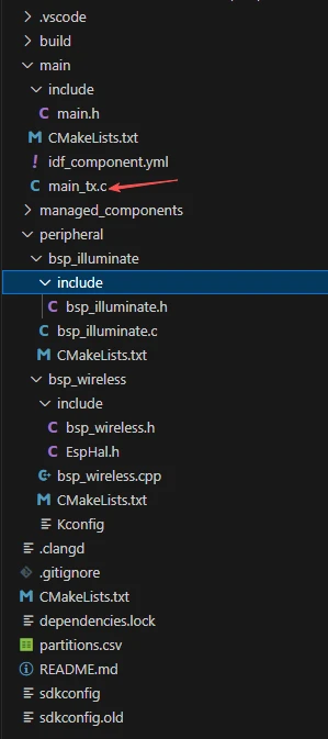
Once opened, you can see the project structure:
This is the transmitter side:
And this is the receiver side:
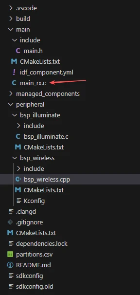
In these two projects, only the implementations in the main functions main_tx.c and main_rx.c differ; all other code files are identical. (For convenience, we have provided two separate main functions for use.)
In this lesson's example, under peripheral\, a new folder named bsp_wireless is created. Inside the bsp_wireless\ folder, there is a new include folder and a CMakeLists.txt file.
The bsp_wireless folder contains the driver file bsp_wireless.cpp.
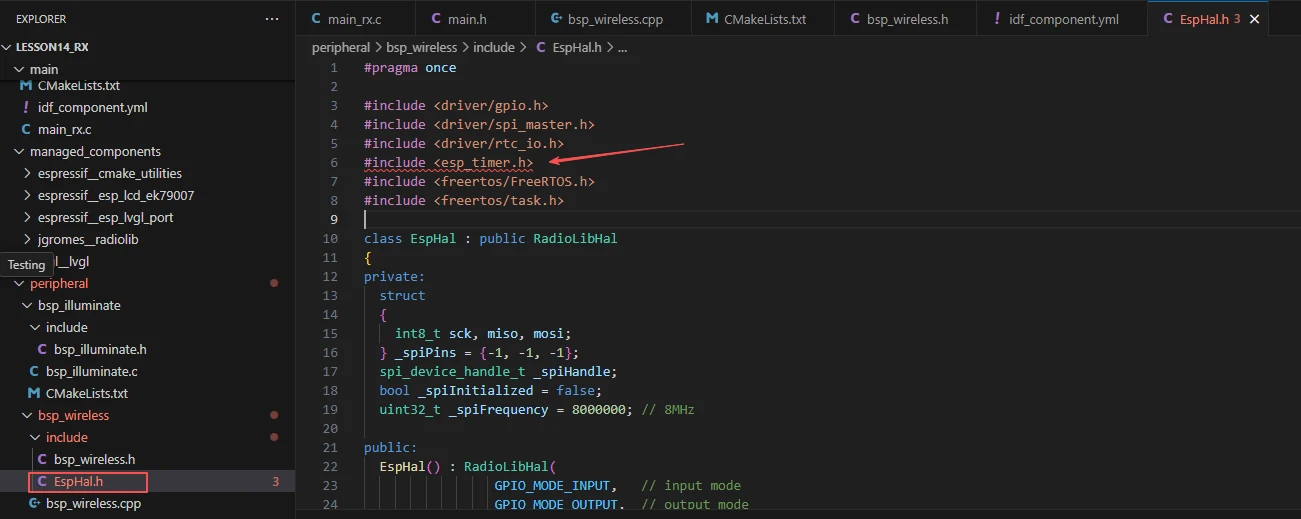
The include folder contains the header files bsp_wireless.h and EspHal.h.
EspHal.h converts ESP-IDF C code into the Arduino-style C++ syntax required by the RadioLib component library.
The CMakeLists.txt file integrates the driver into the build system, allowing the project to use the nRF2401 module send and receive functions implemented in bsp_wireless.cpp.
Additionally, there is bsp_illuminate, our familiar component used to light up the screen and draw text via LVGL.
nRF2401 Communication Code
The code for nRF2401 transmission and reception consists of two files: "bsp_wireless.cpp" and "bsp_wireless.h".
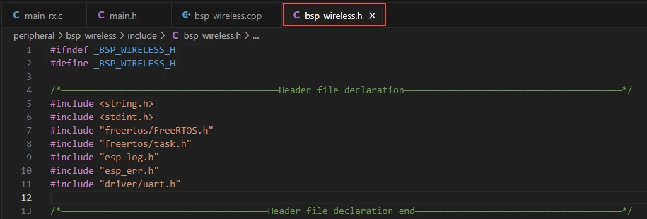
Next, we will first analyze the nRF2401-related code in the "bsp_wireless.h" program.
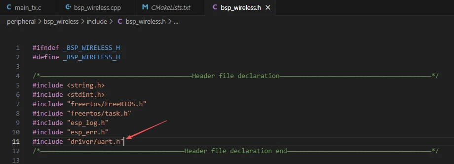
"bsp_wireless.h" is the header file for the nRF2401 wireless module, primarily used to:
-
Declare functions, macros, and variables implemented in "bsp_wireless.cpp" for use by external programs.
-
Allow other .c files to call this module simply by adding #include "bsp_wireless.h".
In other words, it acts as an interface layer that exposes which functions and constants are available to the outside, while hiding the internal details of the module.
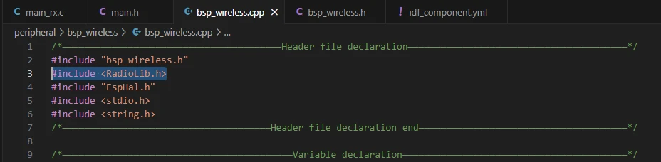
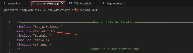
In this component, the libraries we need to use are placed in the "bsp_wireless.h" and "bsp_wireless.cpp" files.
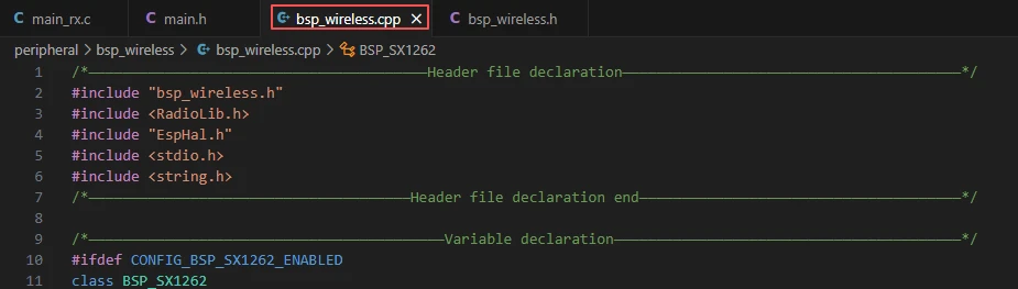
Since the function implementations in bsp_wireless.cpp use the function wrappers provided in EspHal.h, the header file needs to be included in the .cpp file.
For example, #include <RadioLib.h> (this is a library under the networking components)
This inclusion requires us to specify the version of jgromes/radiolib in the idf_component.yml file located in the main folder. Because this is an official library, we rely on it to implement the wireless transmission or reception functionality of the nRF2401 on the Advance-P4.

These three components, which we discussed previously and used in the bsp_illuminate component, are employed to illuminate the screen and render information on the interface using LVGL.
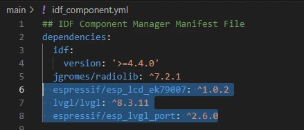
During the subsequent compilation process, the project will automatically download the following libraries: jgromes/radiolib version 7.2.1, espressif/esp_lcd_ek79007 version 1.0.2, lvgl version 8.3.11, and espressif/esp_lvgl_port version 2.6.0. Once downloaded, these networking components will be stored in the managed_components folder. (This is automatically generated after specifying the version numbers.)
Returning to bsp_wireless.h,
this is where we declare the pins used by the wireless module.
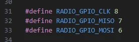

The pin definitions should not be modified; otherwise, the wireless module will not function correctly due to incorrect wiring.
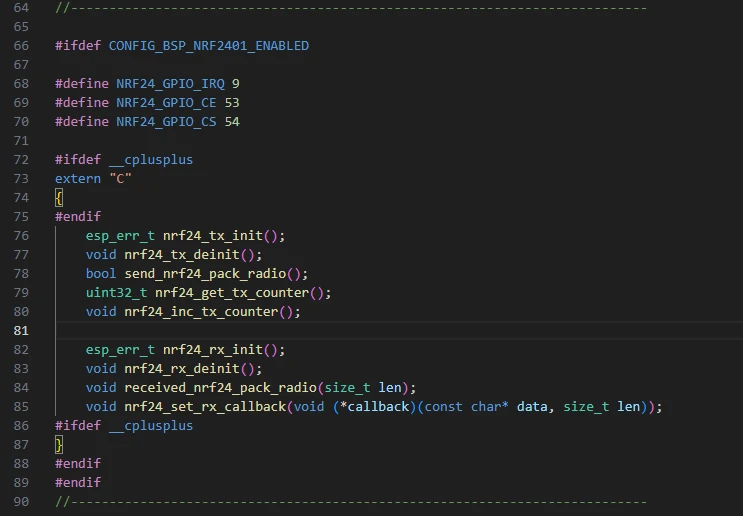
Next, we declare the variables we need to use, as well as the functions. The actual implementations of these functions are in bsp_wireless.cpp. Placing all declarations in bsp_wireless.h is intended to make them easier to call and manage. (We will examine their specific functionality when they are used in bsp_wireless.cpp.)
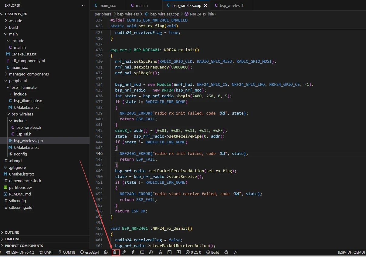
Next, let's take a look at the specific functionality of each function in bsp_wireless.cpp.
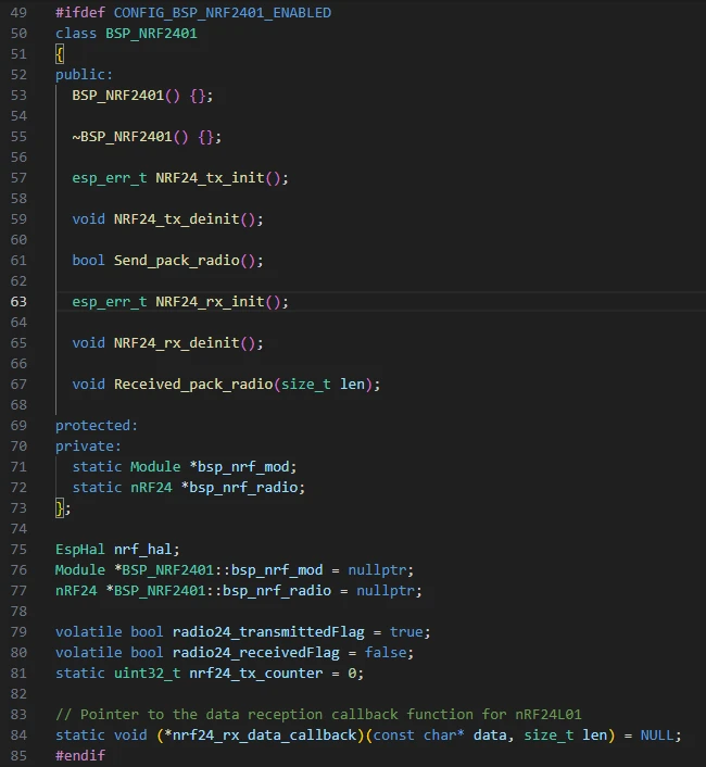
In the bsp_wireless component, BSP_NRF2401 is a BSP driver wrapper class for the nRF24L01 wireless transceiver module. It provides initialization, execution, de-initialization, and callback mechanisms for sending and receiving.
This allows the application layer to complete wireless communication simply by calling straightforward C interface functions (such as nrf24_tx_init() or send_nrf24_pack_radio()), without needing to directly manipulate the underlying SPI registers or the RadioLib interface.
Here, we won't go into a detailed code walkthrough; we will only explain the purpose of each function and the situations in which it should be called.
BSP_NRF2401 Class:
This means:
This code defines a class named BSP_NRF2401 to encapsulate the driver logic for the nRF2401 wireless transceiver module, implementing initialization, sending, and receiving functionalities for wireless communication.
-
The class declares initialization and de-initialization functions for both the transmitter and receiver (such as NRF24_tx_init, NRF24_rx_init), as well as data sending and receiving handling functions (Send_pack_radio, Received_pack_radio).
-
Two static pointers, bsp_nrf_mod and bsp_nrf_radio, are defined to point to the underlying hardware module object and the radio object, respectively, allowing global sharing.
-
nrf_hal is the hardware abstraction layer object, used to manage hardware communication with the chip.
-
Two volatile variables are defined: radio24_transmittedFlag indicates whether transmission is complete, and radio24_receivedFlag indicates whether reception is complete.
-
nrf24_tx_counter is used to record the number of transmissions.
-
Finally, a function pointer nrf24_rx_data_callback is defined to trigger an upper-layer callback when data is received.
Overall, this code establishes the basic control framework for the nRF2401 module, providing a unified interface and state management mechanism for subsequent wireless data transmission and reception.
NRF24_tx_init:
Initializes the transmitter of the nRF2401 module by configuring the SPI interface, creating the communication object, setting the wireless parameters, and specifying the transmission channel, enabling the module to send data.
-
At the beginning of the function, nrf_hal.setSpiPins(RADIO_GPIO_CLK, RADIO_GPIO_MISO, RADIO_GPIO_MOSI) sets the SPI communication pins between the nRF2401 and the main controller (Clock, Master In Slave Out, Master Out Slave In).
-
setSpiFrequency(8000000) sets the SPI clock frequency to 8 MHz to improve communication speed.
-
spiBegin() formally initializes the SPI bus.
-
A module object bsp_nrf_mod is then created via new Module(...), binding the SPI interface along with control pins such as Chip Select (CS), Interrupt (IRQ), and Chip Enable (CE), providing a hardware interface for the nRF24 module.
-
Next, bsp_nrf_radio = new nRF24(bsp_nrf_mod) creates the specific nRF24 radio object and begins the driver logic.
-
Calling begin(2400, 250, 0, 5) completes the core initialization of the wireless module. The parameters represent, in order: operating frequency 2400 MHz (i.e., 2.4 GHz band), data rate 250 kbps, output power level 0 (typically 0 dBm), and communication channel number 5. If initialization fails (return value is not RADIOLIB_ERR_NONE), the error is logged and the function exits.
-
Then, a transmit address is defined as uint8_t addr[] = {0x01, 0x02, 0x11, 0x12, 0xFF}, which is a 5-byte transmit pipe address (similar to a "device address" or "channel identifier" in wireless communication), ensuring that the transmitter and receiver communicate over the same address.
-
setTransmitPipe(addr) sets this address as the current transmit pipe, allowing the module to send data through this channel. If configured successfully, the function returns ESP_OK, indicating that initialization is complete.
Send_pack_radio:
This function sends a wireless data packet through the nRF2401 module and records and prints the transmission status.
-
Specifically, the function first defines a static character array text[32] to store the message to be sent. It then uses snprintf to format the message as "NRF24_TX_Hello World:\<transmit_count>", where \<transmit_count> comes from nrf24_tx_counter and represents the current number of transmissions.
-
The function calculates the message length using strlen and stores it in tx_len.
-
Next, it calls bsp_nrf_radio->transmit((uint8_t *)text, tx_len, 0) to send the message through the nRF2401 module. If the return value is RADIOLIB_ERR_NONE, the transmission is successful, and NRF2401_INFO prints the completion message along with the content sent. Otherwise, it prints a transmission failure message and the error code.
-
The function finally returns true, indicating that the send operation has been executed.
nrf24_tx_init():
This is a C-language interface function used to initialize the nRF2401 transmitter module. Inside the function, a BSP_NRF2401 object obj is instantiated, and its member function NRF24_tx_init() is called to complete SPI configuration, wireless parameter setup, and transmit pipe address configuration, returning the initialization result.
Purpose: Provides a unified interface for upper-layer or C code to prepare the nRF2401 module for data transmission.
nrf24_tx_deinit():
This is a C-language interface function used to release or shut down the nRF2401 transmitter resources. It creates a BSP_NRF2401 object internally and calls its member function NRF24_tx_deinit(), putting the wireless module into an idle state and closing the SPI bus.
Purpose: Called when the transmission task is finished or the module is no longer in use, safely releasing transmitter resources.
send_nrf24_pack_radio():
This is a C-language interface function used to send a data packet via the nRF2401. Internally, it creates a BSP_NRF2401 object and calls its member function Send_pack_radio() to send the formatted message and print the transmission result.
Purpose: Provides a simple interface for the upper layer to send wireless data without needing to handle the underlying driver details.
nrf24_get_tx_counter():
This is a C-language interface function used to get the current value of the nRF2401 transmit counter nrf24_tx_counter.
Purpose: Allows upper-layer programs to obtain the number of packets sent, useful for statistics or debugging.
nrf24_inc_tx_counter():
This is a C-language interface function used to increment the transmit counter nrf24_tx_counter by 1.
Purpose: Updates the counter after each successful packet transmission, used to record the number of sends or to mark a sequence number in the message.
set_rx_flag():
This is a static internal function called within the receive interrupt or callback, used to set radio24_receivedFlag to true, indicating that the nRF2401 module has received new data.
Purpose: Serves as a receive event flag to notify the upper-layer program that new data is available for processing.
NRF24_rx_init:
This function, BSP_NRF2401::NRF24_rx_init(), initializes the receiver side of the nRF2401 module, enabling it to receive wireless data.
-
Specifically, the function first sets the SPI communication pins using nrf_hal.setSpiPins(RADIO_GPIO_CLK, RADIO_GPIO_MISO, RADIO_GPIO_MOSI), sets the SPI clock frequency to 8 MHz with setSpiFrequency(8000000), and initializes the SPI bus using spiBegin().
-
A module object bsp_nrf_mod is then created via new Module(...), binding the SPI interface and control pins. Next, bsp_nrf_radio = new nRF24(bsp_nrf_mod) creates the nRF24 radio object.
-
Calling bsp_nrf_radio->begin(2400, 250, 0, 5) initializes the wireless parameters, where 2400 represents the 2.4 GHz operating frequency, 250 is the data rate in kbps, 0 is the output power level, and 5 is the communication channel. If an error occurs, it logs the failure and returns.
-
A receive pipe address is defined as addr[] = {0x01, 0x02, 0x11, 0x12, 0xFF}. The function then calls setReceivePipe(0, addr) to set pipe 0 as the receive address, ensuring the module only receives data sent to this address.
-
setPacketReceivedAction(set_rx_flag) registers a receive callback, setting radio24_receivedFlag to notify the upper layer. Finally, startReceive() puts the module into receive mode. If successful, the function returns ESP_OK.
Received_pack_radio:
This function, BSP_NRF2401::Received_pack_radio(size_t len), handles data packets received by the nRF2401 module.
-
Specifically, the function first checks the receive flag radio24_receivedFlag. If it is true, it indicates that new data has arrived. The flag is then reset to false to avoid repeated processing.
-
A buffer data[len] is defined to store the received data, and bsp_nrf_radio->readData(data, len) is called to read len bytes from the module.
-
If the return value is RADIOLIB_ERR_NONE, the data is successfully read. The function uses NRF2401_INFO to print a success message along with the received data, and checks whether the callback function pointer nrf24_rx_data_callback has been registered. If it is registered, the callback is called to notify the upper-layer application.
If reading fails, NRF2401_ERROR prints the error code. Finally, bsp_nrf_radio->startReceive() is called to re-enter receive mode, waiting for the next data packet.
nrf24_rx_init()
This is a C-language interface function used to initialize the receiver side of the nRF2401 module. Internally, a BSP_NRF2401 object obj is instantiated, and its member function NRF24_rx_init() is called to complete SPI configuration, wireless parameter initialization, receive pipe address setup, and callback registration, returning the initialization result.
Purpose: Provides a unified interface for upper-layer or C-language programs to prepare the nRF2401 module for data reception.
nrf24_rx_deinit()
This is a C-language interface function used to release the nRF2401 receiver resources. Internally, a BSP_NRF2401 object is created, and its member function NRF24_rx_deinit() is called to put the module into an idle state, clear callbacks, and close the SPI bus.
Purpose: Called when the reception task is finished or the module is no longer in use, safely releasing receiver resources.
received_nrf24_pack_radio(size_t len)
This is a C-language interface function used to handle received data packets. Internally, it creates a BSP_NRF2401 object and calls its member function Received_pack_radio(len) to read the data, log the results, and notify the upper-layer application via a callback.
Purpose: Provides an upper-layer interface to trigger the nRF2401 data reception processing flow.
nrf24_set_rx_callback(void (*callback)(const char* data, size_t len))
This is a C-language interface function used to register a callback for received data, notifying the upper-layer application when data arrives. Internally, the passed function pointer is saved to nrf24_rx_data_callback.
Purpose: Allows the upper-layer program to set a custom callback for immediate processing or response upon receiving nRF2401 data.
We will conclude the introduction of the bsp_wireless component here. It is enough for everyone to understand how to call these interfaces.
If you want to use it, you also need to configure the CMakeLists.txt file under the bsp_wireless folder. This file, located in the bsp_wireless directory, primarily tells the ESP-IDF build system (CMake) how to compile and register the bsp_wireless component.
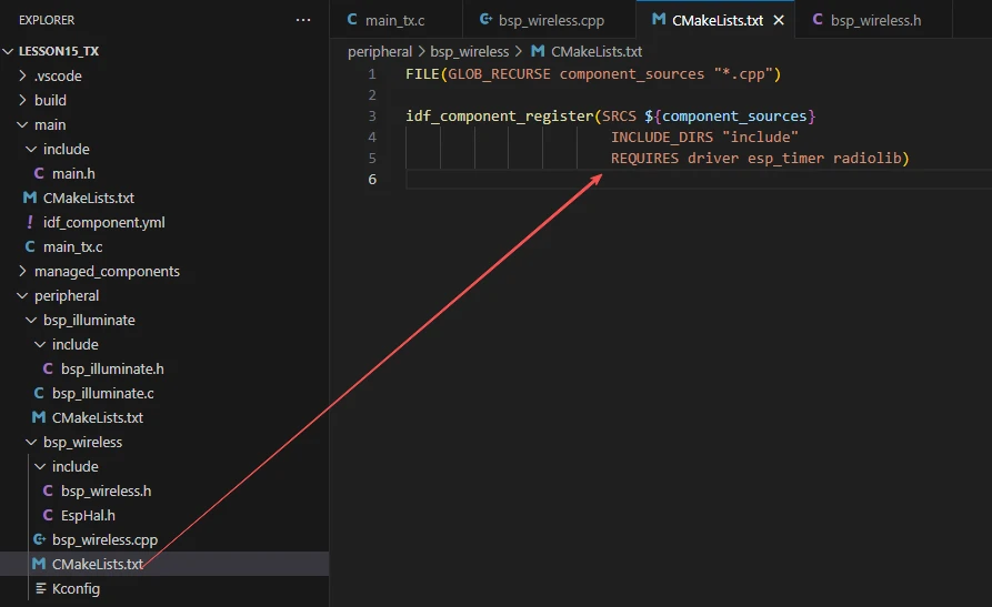
The reason only driver, esp_timer, and radiolib are listed is that we use them in bsp_wireless.h and bsp_wireless.cpp. (Other libraries are system libraries, so they do not need to be added.)
As well as esp_timer, which is used in the EspHal.h file.
Main Function
The main folder is the core directory for program execution and contains the main executable file main_tx.c.
The main folder should be added to the build system in the CMakeLists.txt file.
This is the entry file of the entire application. In ESP-IDF, there is no int main(); instead, execution starts from void app_main(void).
Let's first explain the transmitter's main function file, main_tx.c, to see how it calls the interfaces to send information via the nRF2401.
When the program runs, the general workflow is as follows:
-
First, Hardware_Init() is called in app_main() to initialize the hardware. This includes configuring the LDO power channels, initializing the LCD display and turning on the backlight, and initializing the nRF24L01 wireless module.
-
Next, lvgl_show_counter_label_init() is called to create and display an LVGL label on the screen for showing the transmit counter.
-
The program then creates two FreeRTOS tasks:
-
ui_counter_task reads the nRF24L01 transmit counter every second and updates the screen label.
-
nrf24_tx_task increments the transmit counter every second and calls send_nrf24_pack_radio() to send a wireless data packet, achieving wireless transmission.
The entire process uses task scheduling to keep the display and transmission synchronized, forming a loop system that automatically sends data every second while showing the real-time count on the LCD.
Next, let's explain the main code in main_tx.c.

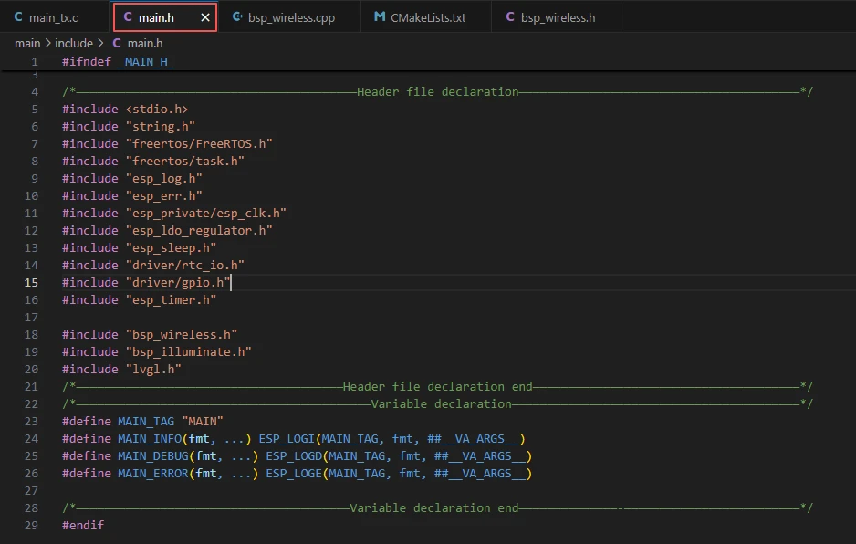
Includes the custom main header file main.h, which typically contains logging macros, declarations for peripheral initialization, and other interface header files that need to be used.
Below is the content of main.h:
Let's continue to look at the contents of main_tx.c.
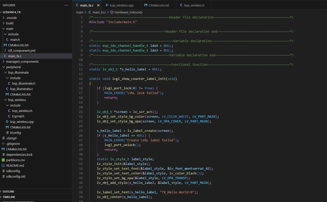
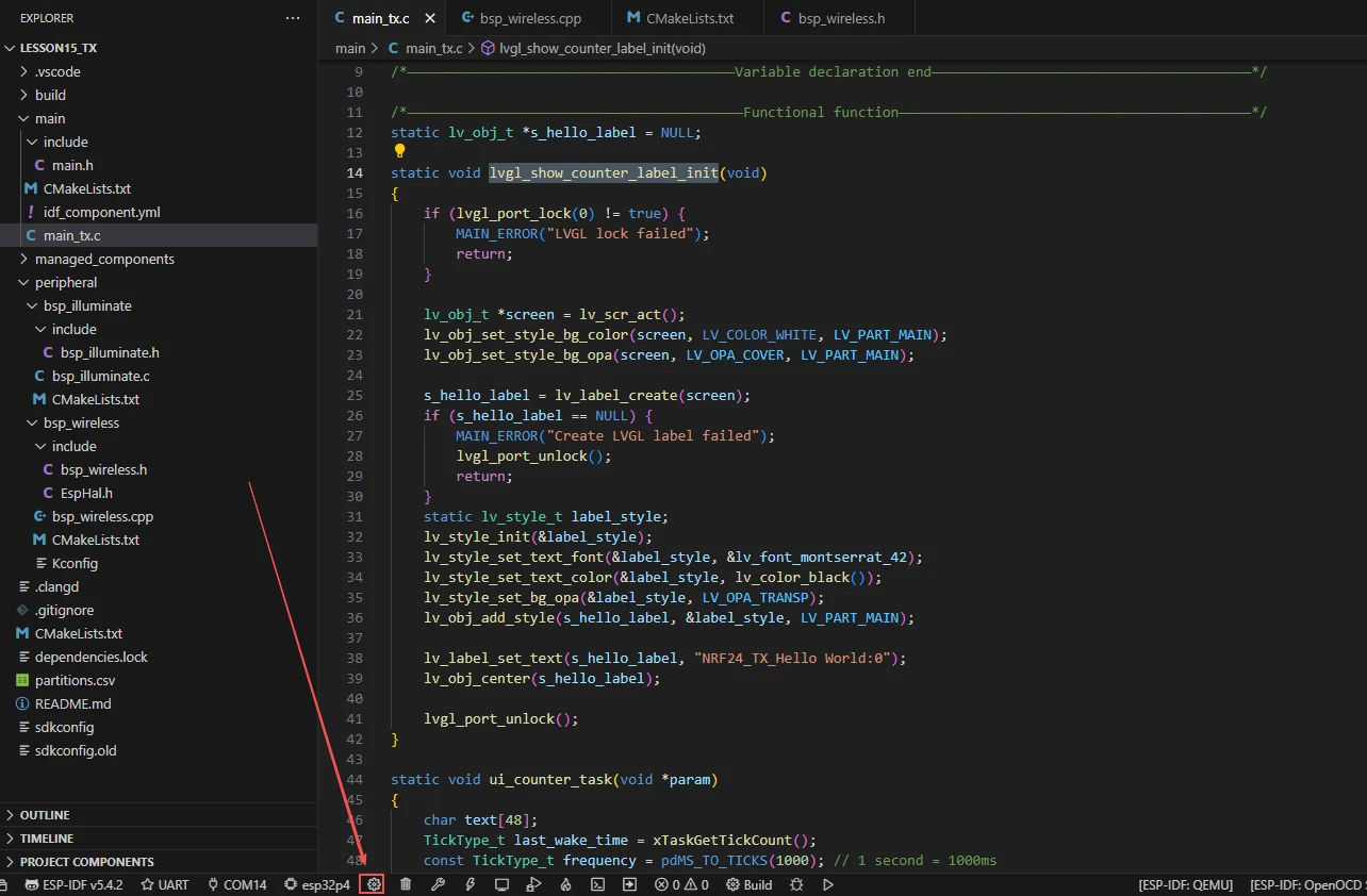
lvgl_show_counter_label_init:
The function lvgl_show_counter_label_init() initializes the counter label on the LVGL display, used to show the nRF24L01 transmit count. Its workflow and purpose of each step can be summarized as follows:
-
First, lvgl_port_lock(0) is called to lock LVGL resources, preventing concurrent access.
-
The current active screen is obtained via lv_scr_act(), and the background is set to white and fully covering.
-
A label is created using lv_label_create(screen) and checked for successful creation; if creation fails, the lock is released and the function returns.
-
The label style is initialized with lv_style_init, setting the font size, text color to black, and background to transparent, and the style is applied to the label.
-
lv_label_set_text sets the initial text to "NRF24_TX_Hello World:0", and lv_obj_center centers the label on the screen.
-
Finally, lvgl_port_unlock() releases the LVGL resource lock.
Overall, this function creates and initializes a styled, dynamically updatable label to display the transmit count.
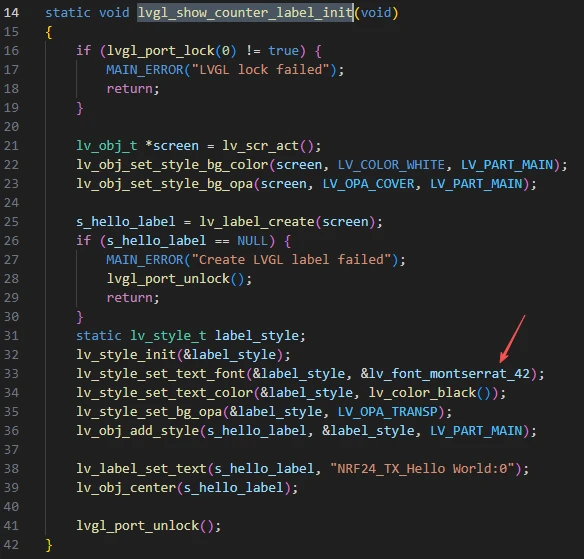
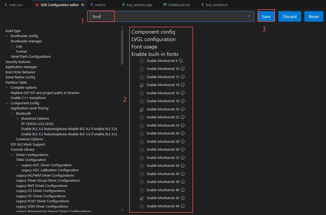
If you want to change the LVGL font size, you need to enable the fonts in the SDK configuration.
Steps:
Click on the SDK configuration options
Search for font, then select the font size you want to use. After making the changes, be sure to save them.
ui_counter_task:
The function ui_counter_task() is responsible for refreshing the nRF24L01 transmission count information displayed on the LCD every second.
Its workflow and the role of each part can be summarized as follows:
-
First, define a character array text[48] to store the display text.
-
Record the system tick count last_wake_time when the task starts, and set the loop interval to 1000ms (1 second).
-
Enter an infinite loop. In each loop, first read the current transmission count using nrf24_get_tx_counter(), and format it into the string "NRF24_TX_Hello World:\<count value>" using snprintf.
-
Attempt to lock the LVGL resource with lvgl_port_lock(0). If successful and the label exists, call lv_label_set_text to update the display text and release the lock.
-
Finally, use vTaskDelayUntil to delay according to absolute time to ensure an accurate one-second cycle, realizing the function of updating the display every second.
Overall, its role is to continuously refresh the transmission count on the interface to achieve real-time display.
Hardware_Init:
The function Hardware_Init() is used to initialize hardware modules when the program starts, ensuring all parts of the system can work properly.
-
First, it acquires the LDO3 (2.5V) and LDO4 (3.3V) power channels respectively through esp_ldo_acquire_channel(). If the acquisition fails, it calls init_or_halt() to wait in a loop and print error messages, ensuring stable power supply.
-
Then it calls display_init() to initialize the LCD hardware and LVGL graphics library, which must be completed before turning on the backlight; otherwise, the display may work abnormally.
-
Next, it calls set_lcd_blight(100) to turn on the LCD backlight and set the maximum brightness to 100, with errors also checked via init_or_halt().
-
Finally, it calls nrf24_tx_init() to initialize the nRF2401 wireless transmission module. If initialization fails, it is also handled through init_or_halt().
Overall, its role is to provide a reliable hardware environment for the screen display, backlight, and wireless communication module, ensuring the subsequent functions of the program can run smoothly. It is usually called during system startup in app_main().
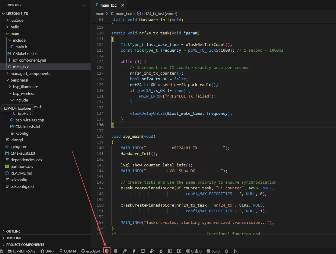
nrf24_tx_task:
The function nrf24_tx_task() is responsible for transmitting nRF24L01 wireless data packets once per second and maintaining the transmission counter.
Its workflow and the role of each part can be summarized as follows:
-
First, it records the system tick count last_wake_time when the task starts and sets the loop interval to 1000ms (1 second).
-
It enters an infinite loop. In each iteration, it first calls nrf24_inc_tx_counter() to increment the transmission counter.
-
Then, it calls send_nrf24_pack_radio() to transmit a data packet containing the current count. It uses nrf24_tx_OK to check if the transmission is successful; if failed, it prints an error log.
-
Finally, it uses vTaskDelayUntil(&last_wake_time, frequency) to delay by 1 second based on absolute time, ensuring precise transmission intervals.
Overall, its role is to automatically send count data every second, update the counter, and implement the timed wireless transmission function of the nRF24L01.
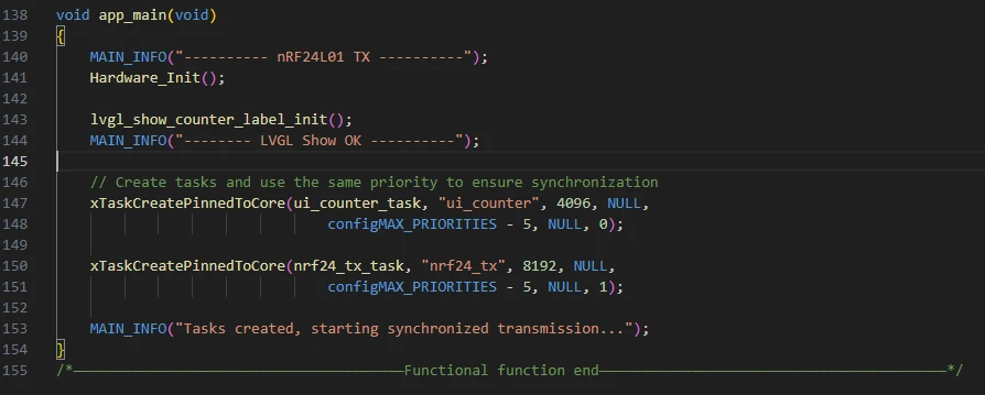
app_main:
app_main() is the program entry function, responsible for completing hardware initialization, interface display setup, and launching wireless transmission and interface refresh tasks to implement the synchronized transmission and display functions of the nRF24L01.
The specific workflow is summarized as follows:
-
First, it prints the log "---------- nRF24L01 TX ----------" to indicate program startup.
-
It calls Hardware_Init() to initialize hardware, including LDO power supplies, LCD display, and the nRF24L01 module.
-
It invokes lvgl_show_counter_label_init() to create and initialize an LVGL label for displaying the transmission count, and prints the log "-------- LVGL Show OK ----------".
-
Then, it uses xTaskCreatePinnedToCore to create two FreeRTOS tasks: ui_counter_task (for refreshing the transmission count display on the LCD every second) and nrf24_tx_task (for transmitting wireless data packets once per second). Both tasks use the same priority to maintain synchronization.
-
Finally, it prints the log "Tasks created, starting synchronized transmission..." to indicate that task creation is complete and the system has started synchronized transmission and interface display.
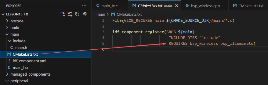
Finally, let's take a look at the "CMakeLists.txt" file in the main directory.
The role of this CMake configuration is as follows:
-
Collect all .c source files in the main/ directory as the source files of the component.
-
Register the main component with the ESP-IDF build system, and declare that it depends on the custom component bsp_wireless and the custom component bsp_illuminate.
This ensures that during the build process, ESP-IDF knows to build bsp_wireless and bsp_illuminate first, and then build the main component.
The above is the main function code for the transmitter. Next, let's take a look at the main function code for the receiver.
Open your receiver code in the same way as you did for the transmitter.
rx_data_callback:
rx_data_callback() is the callback function triggered when the nRF24L01 receives data. Its role is to count received data packets, update the interface display, and print logs.
The specific workflow is as follows:
-
First, rx_packet_count++ increments the receive counter by 1.
-
Then, it attempts to acquire the LVGL lock with lvgl_port_lock(0) to ensure thread safety. If successful and s_rx_label has been created, it formats the current receive count into the string "NRF24_RX_Hello World:i" using snprintf and calls lv_label_set_text to update the display label.
-
After updating the interface, it releases the lock with lvgl_port_unlock().
-
Finally, it formats the receive count using the local buffer rx_display_text and prints a log via MAIN_INFO, facilitating debugging and monitoring of reception status.
Overall, its role is to promptly update the interface and logs whenever the nRF24L01 receives data, enabling real-time feedback.
lvgl_show_rx_interface_init:
lvgl_show_rx_interface_init() is a function used to initialize the LVGL display interface for the nRF24L01 receiver. Its role is to create and layout interface elements for displaying received data.
The specific workflow is as follows:
-
First, it attempts to acquire the LVGL lock with lvgl_port_lock(0) to ensure thread safety. If it fails, it prints an error and returns.
-
It retrieves the screen object with lv_scr_act() and sets the background color to white with full opacity.
-
It creates a title label title_label and sets its text to "nRF24L01 RX Receiver". It initializes the style title_style (large font, black text, transparent background), applies this style, and positions the title at the top center of the screen.
-
Next, it creates a receive information label s_rx_label with initial text "NRF24_RX_Hello World:0". It defines the style rx_style (large font, black text, transparent background), applies this style, and positions the label slightly above the center of the screen.
-
Finally, it releases the LVGL lock with lvgl_port_unlock().
Overall, its role is to provide an LVGL interface for the receiver to display received data in real time.
Hardware_Init:
This function is identical to the hardware initialization function described earlier. It initializes the LDOs, screen, and nRF2401 module in the same way. The only difference here is that the nRF2401 module is configured in receiver mode.
nrf24_rx_task:
nrf24_rx_task() is a FreeRTOS task function for the nRF2401 receiver, responsible for continuously polling and receiving wireless data.
-
The function enters an infinite loop while(1) to ensure continuous operation.
-
In each loop iteration, it calls received_nrf24_pack_radio(32) to check for and process received data packets. The parameter 32 represents the maximum packet length supported by the nRF24L01.
-
It then delays for 10 milliseconds using vTaskDelay(10 / portTICK_PERIOD_MS) to reduce CPU usage.
Overall, its role is to periodically poll the nRF2401 receive buffer and trigger processing/callbacks when data is available, enabling real-time data reception.
app_main:
-
app_main() is the entry function of the nRF24L01 receiver program, used to initialize hardware, the interface, and reception tasks.
-
First, the function prints startup information via MAIN_INFO, then calls Hardware_Init() to initialize hardware peripherals (such as power management, LCD, and the nRF24L01 module).
-
Next, it invokes lvgl_show_rx_interface_init() to initialize the LVGL display interface and prints a confirmation log.
-
Subsequently, it registers the reception callback function using nrf24_set_rx_callback(rx_data_callback)---this function is used to process data and update the interface when data is received, and a log is printed for confirmation.
-
Finally, it creates the FreeRTOS task nrf24_rx_task using xTaskCreatePinnedToCore(), which continuously polls for and receives data on the specified core. A log is printed to indicate that the receiver has started.
-
This concludes our explanation of the main function code for both the receiver and transmitter of the nRF24L01.
We have now finished explaining the main function code for both the receiver and the transmitter.
Complete Code
Kindly click the link below to view the full code implementation.
GitHub Link
Programming Steps
Now that the code is ready, the next step is to flash it onto the ESP32-P4 so we can observe the actual operation.
First, connect the Advance-P4 device to your computer using a USB cable.
Before starting the preparation for flashing, first delete all compiler-generated files to restore the project to its initial "unbuilt" state. This ensures that subsequent compilations are not affected by your previous operations.
Here, follow the steps from the first section to select the ESP-IDF version, code upload method, serial port number, and target chip.
Next, we need to configure the SDK.
Click the icon shown in the figure below.
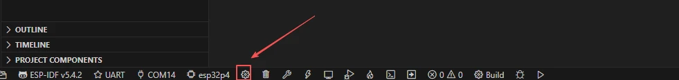
After waiting for a short loading period, you can proceed with the relevant SDK configurations.
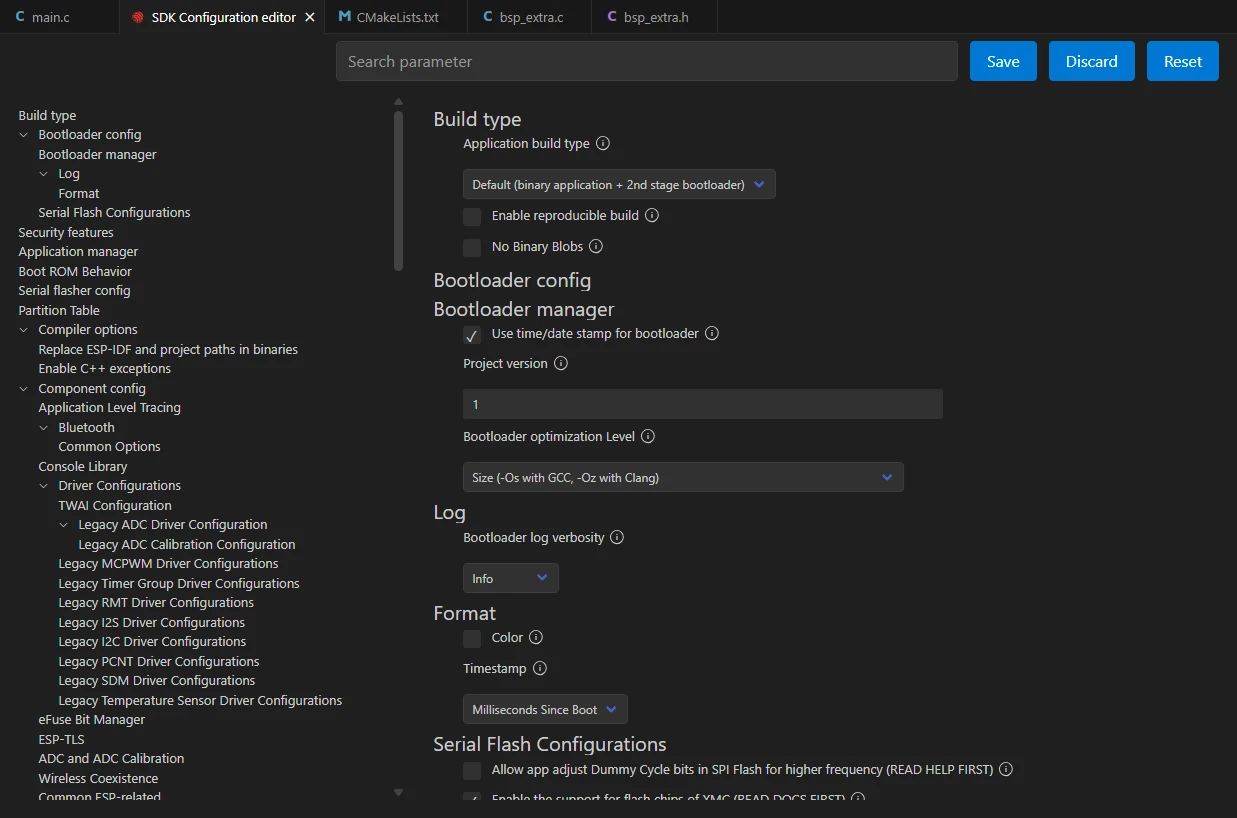
Then, enter "flash" in the search box to search.
(Make sure your flash configuration matches mine.)
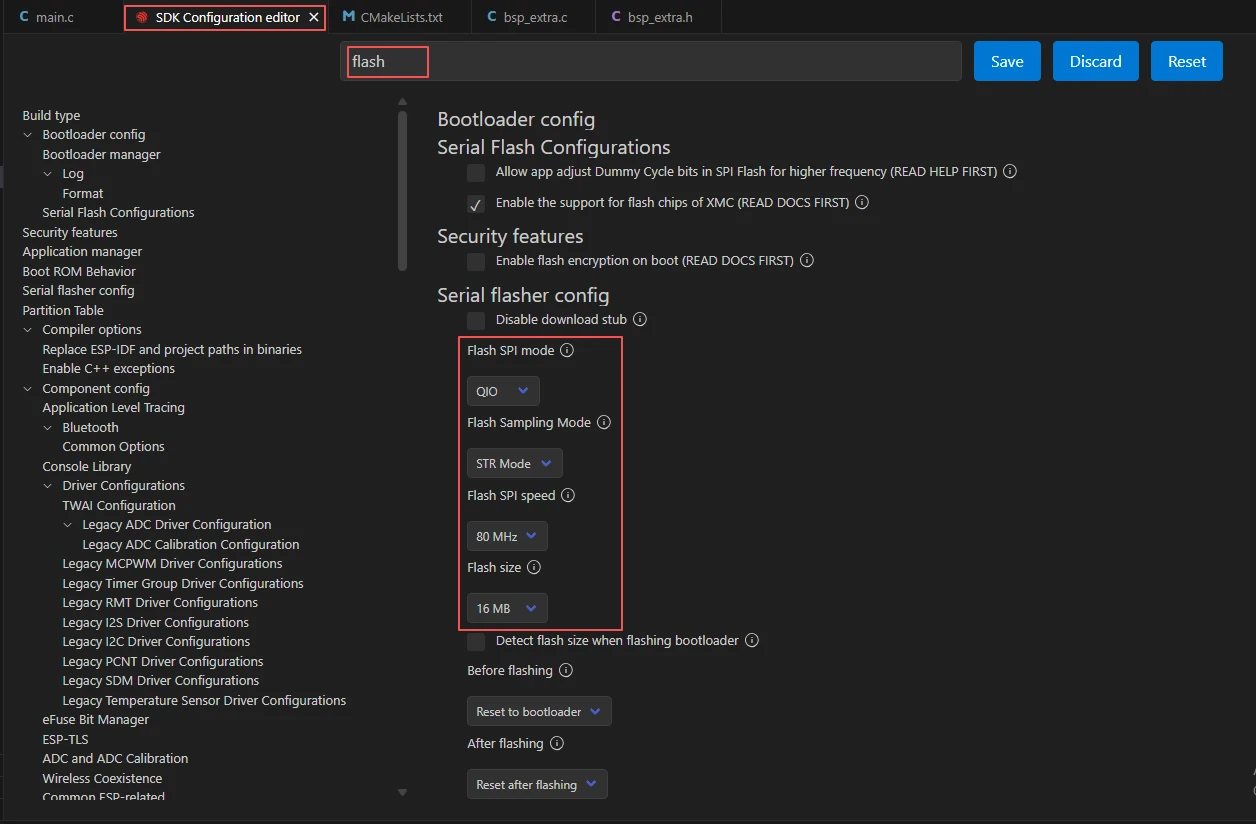
After completing the configuration, remember to save your settings.
Next, we will compile and flash the code (detailed in the first lesson).
Here, we also want to share a very convenient feature with you: a single button that can execute compilation, upload, and open the monitor in one go.
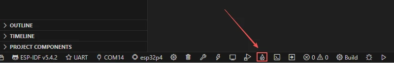
After waiting for a moment, the code will finish compiling and uploading, and the monitor will open automatically.
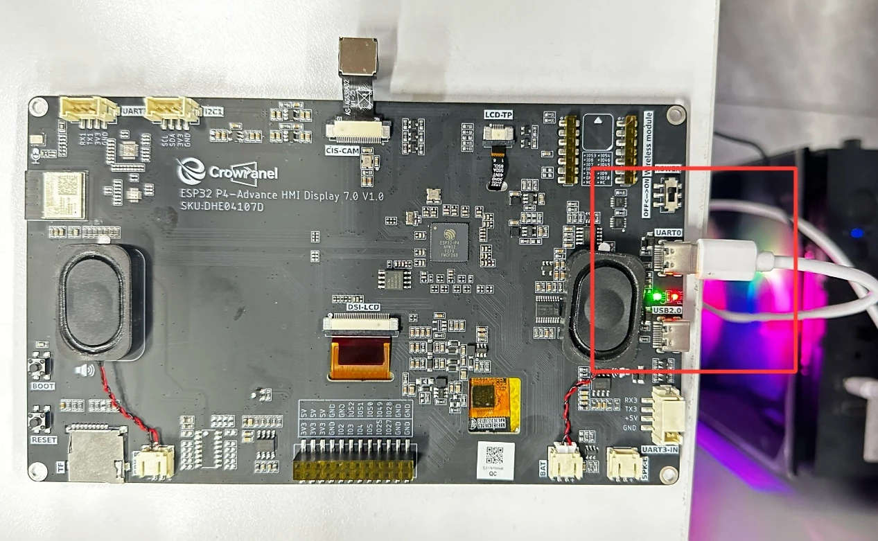
At this point, remember to connect your Advance-P4 using an additional Type-C cable via the USB 2.0 interface. This is because the maximum current provided by a computer's USB-A port is generally 500mA, and the Advance-P4 requires a sufficient power supply when using multiple peripherals---especially the screen. (It is recommended to connect it to a charger.)
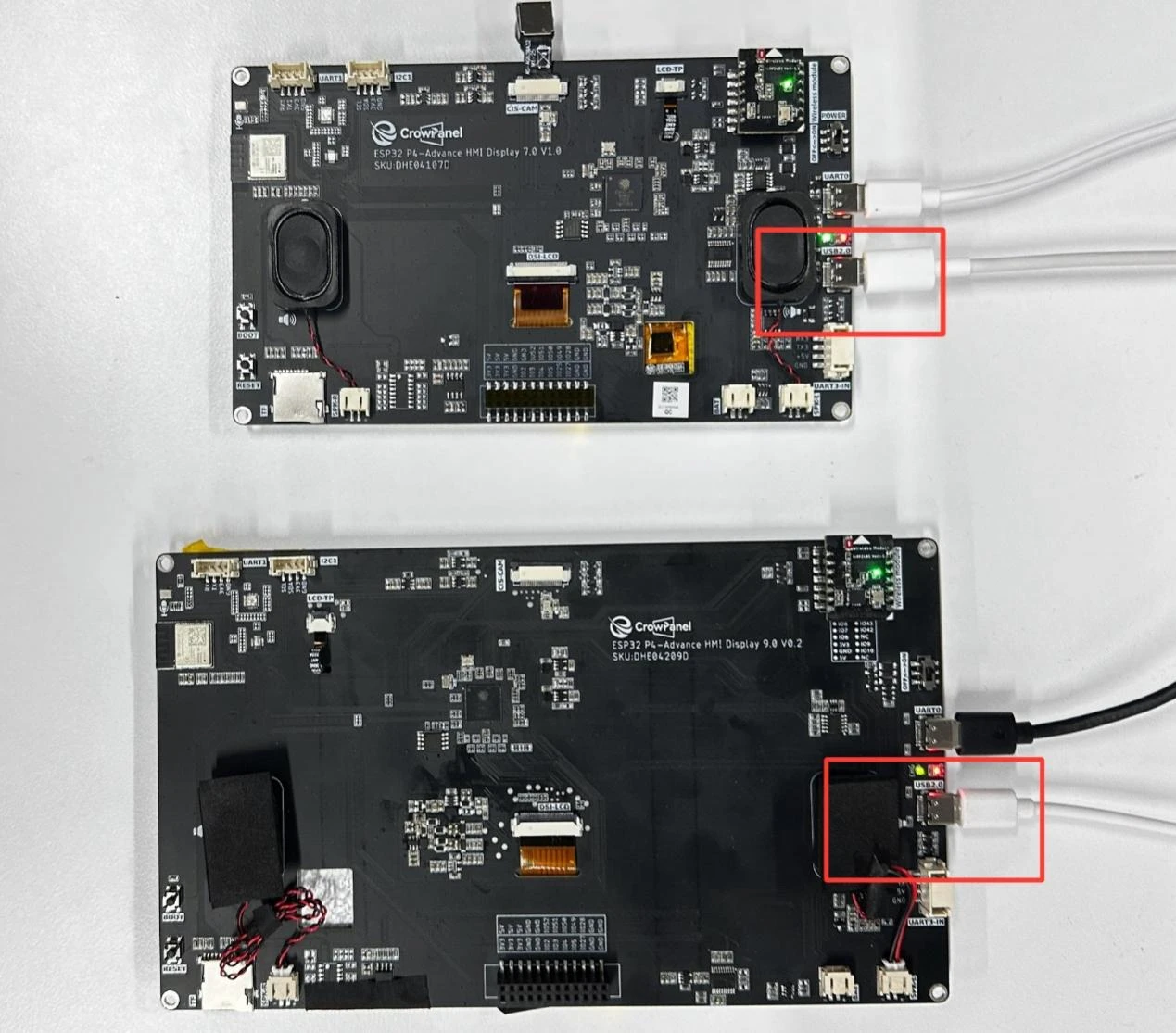
Insert the nRF2401 wireless RF module into each of the two Advance-P4 development boards.
After running the code on both boards respectively, you will be able to see on the transmitter's Advance-P4 screen that the nRF2401 module is sending data labeled "NRF24_TX_Hello World:i", where "i" increases by 1 every second.
Similarly, on the receiver's Advance-P4 screen, you will see that the nRF2401 module is receiving data labeled "NRF24_RX_Hello World:i"; after receiving the message, "i" will also increase by 1 every second.