1.28 ESPHOME Lesson02 Light Up the Screen
1. Course Introduction
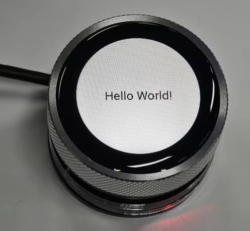
In this lesson, we will use ESPHome to write code to light up the CrowPanel 1.28inch-HMI ESP32 Rotary Display and display “Hello World” on the screen.
2. Learning Objectives
Learn how to drive the rotary display
Light up the screen and print hello world on the display
3. Project Demonstration

4. Example Code Download Link and Key Code Explanation
Click the GitHub link below to download the complete code:
Next, we will explain the key parts of this code and how the screen display is driven on the ESPHome platform.
First, establish a core understanding
This code is not traditional "programming code" (such as Python/C++), but an ESPHome configuration file (YAML format) — you can think of it as a "manual" written for the ESP32: telling the ESP32 what hardware to connect, what functions to implement, and how to communicate with Home Assistant.
The core rule of YAML is to describe the configuration required by the program in a “manual-style text format” rather than writing complex code. In YAML, the most important aspect is that indentation represents hierarchical relationships — content at the same level must be left-aligned, and child content must be indented two spaces more than the parent (Tabs are not allowed). The program determines “who belongs to whom” based on indentation; each line is usually in the form of key: value, where the left side of the colon is the name and the right side is the specific content; if a key contains multiple items, use - to represent a list; comments use #, which are only for human reading and are not executed by the program; YAML is extremely sensitive to case and spaces — one missing space or one extra Tab may cause the configuration to fail.
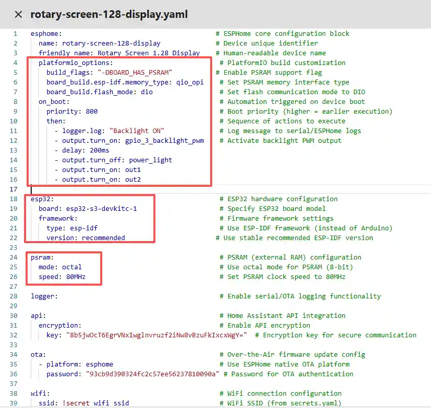
(1) Basic Information & Compilation Configuration (esphome block)
This is the "identity card" and "compilation rules" of the entire device, telling ESPHome how to compile the firmware and what the device is called.
esphome:
  name: rotary-screen-128-display
  friendly_name: Rotary_Screen_1.28_Display
  platformio_options:
    build_flags: "-DBOARD_HAS_PSRAM"
    board_build.esp-idf.memory_type: qio_opi
    board_build.flash_mode: dio
  on_boot:
    priority: 800
    then:
      - logger.log: "Backlight ON"
      - output.turn_on: gpio_3_backlight_pwm
      - delay: 200ms
      - output.turn_off: power_light
      - output.turn_on: out1
      - output.turn_on: out2
This section is the core configuration of ESPHome, essentially telling the system “what kind of device this is, how to compile it, and what to do after power-on.”
name is the unique identifier of the device in ESPHome and Home Assistant, and it can only use lowercase letters and hyphens;
friendly_name is the human-readable name and does not affect program logic.
platformio_options are parameters for the underlying compiler. Here you explicitly inform the ESP32-S3 board that it has PSRAM, that PSRAM uses the OPI interface, and that Flash uses DIO mode; otherwise, with a large display + LVGL, memory may easily be insufficient and result in a black screen.
on_boot defines actions executed immediately after power-on, and priority: 800 means “execute immediately after most components are initialized.”
Here, gpio_3_backlight_pwm is enabled, which actually turns on the screen backlight pin GPIO46, described in detail later in the output section.
Here, out1 corresponds to GPIO1. We need to pull this pin high so that current can flow through the screen and the screen can light up. In other words, if you only enable the screen backlight pin GPIO46, the screen will still not light up; you must also enable GPIO1 so that current can flow and the screen can illuminate. Both are indispensable for lighting up the screen.
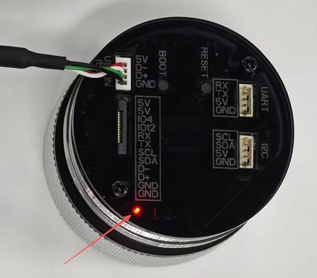
Here, out2 corresponds to GPIO2. This pin supplies power to the UART interface and I2C interface on the 1.28inch rotary display. This pin must be pulled high for the UART and I2C interfaces to function and for current to flow.
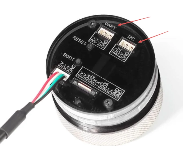
Here, power_light corresponds to pin GPIO40. This pin controls the power indicator LED. When the 1.28inch rotary display is powered on, this pin lights up and serves only as an indicator. (This pin lights up when the level is pulled low.)
(2) Tell ESPHome Which Chip You Are Using
This section is for selecting the hardware and development framework.
board tells ESPHome that you are using the ESP32-S3 series; pin mapping, power management, USB, and PSRAM initialization will all be handled according to the S3 specifications.
framework: esp-idf means you are using the official ESP-IDF framework rather than Arduino — this is very important for LVGL, high-resolution displays, SPI DMA, and PSRAM, as the Arduino framework can easily become unstable in these scenarios.
version: recommended means using the stable IDF version currently validated by ESPHome to avoid version-related issues.
(3) psram: Preparing a “Memory Warehouse” for Large Screens and LVGL
This section is the external PSRAM configuration.
The built-in internal RAM of the ESP32-S3 is very limited; a round screen + ILI9xxx + LVGL almost certainly requires PSRAM.
mode: octal means using 8-line OPI mode (high speed and large bandwidth), and speed: 80MHz is a commonly used stable configuration for S3 + display.
If this is not configured, LVGL’s framebuffer, font cache, and drawing buffer may fail to allocate. The most typical symptom is: flashing succeeds, but the screen remains completely black.
(4) logger: —— Serial “Life Probe”
This section enables the serial logging function.
It does not directly control any hardware, but it is extremely important for beginners:
-
You can see whether the ESP has started
-
Whether it has entered on_boot
-
Whether SPI / Display / LVGL have been initialized
Without logger, if the screen turns black, you will hardly know where the problem occurred.
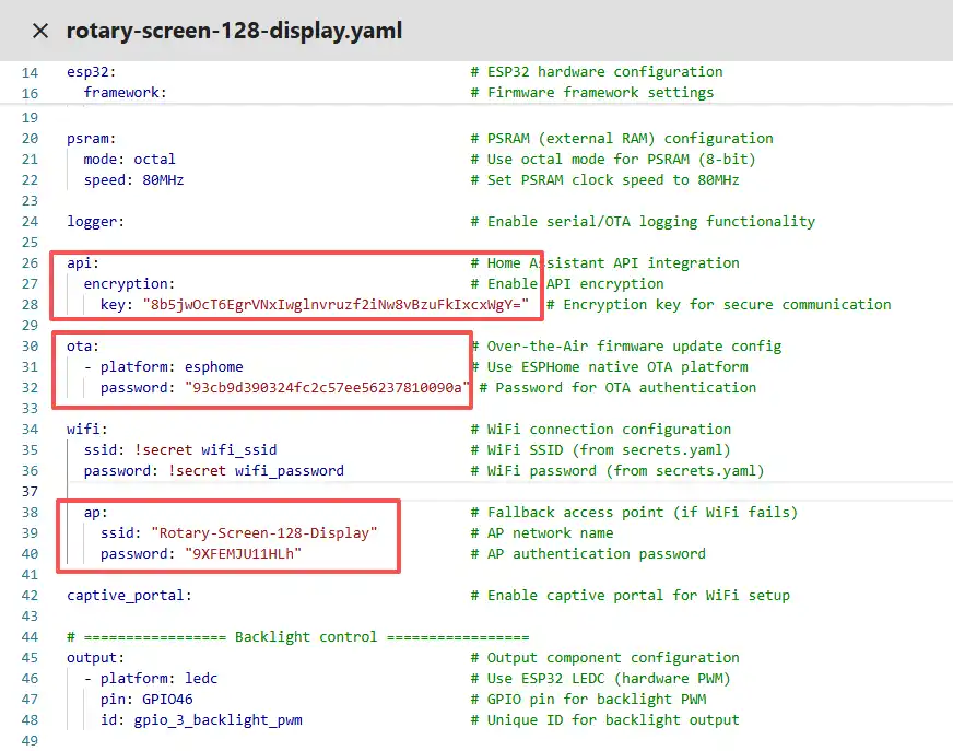
(5) api: —— Communicating with Home Assistant
api:                                            # Home Assistant API integration
  encryption:                                   # Enable API encryption
    key: "8b5jwOcT6EgrVNxIwglnvruzf2iNw8vBzuFkIxcxWgY="
This section is the communication interface between ESPHome and Home Assistant.
Even if you are currently only displaying “Hello World,” ESPHome is fundamentally designed for IoT devices; the api allows you to perform remote control, update interfaces, and send data in the future.
The encryption key is used to prevent unauthorized control within the local network.
(6) ota: —— Wireless Upgrade Without Repeatedly Plugging in USB
This section allows you to flash firmware directly via Wi-Fi in the future. This OTA configuration matches the firmware flashing process you will perform later. After the device successfully connects to the network, you will be able to remotely upload programs via Wi-Fi. (The prerequisite is that you first upload the bin file using Manual download.)
(7) wifi: + captive_portal: —— Network Connection and Emergency AP
wifi:
  ssid: !secret wifi_ssid
  password: !secret wifi_password
  ap:
    ssid: "Rotary-Screen-128-Display"
    password: "9XFEMJU11HLh"
captive_portal:
This section is the Wi-Fi network configuration.
Under normal circumstances, it connects to your home router; if the connection fails, it automatically enables a hotspot (AP), allowing you to reconnect using your phone and reconfigure it.
captive_portal is a web-based configuration interface that prevents the device from becoming unusable.
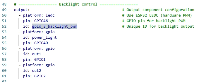
(8) output: —— The “Actuators” of GPIO and PWM
output:
  - platform: ledc
    pin: GPIO46
    id: gpio_3_backlight_pwm
  - platform: gpio
    id: power_light
    pin: GPIO40
  - platform: gpio
    id: out1
    pin: GPIO1
  - platform: gpio
    id: out2
    pin: GPIO2
This section defines the output capabilities of the ESP32.
ledc is the ESP32 hardware PWM, which you use to control backlight brightness
gpio is standard high/low level output, used to control power, enable pins, and peripherals
The philosophy of ESPHome is: first define “what can be controlled,” then use it elsewhere.
(This was explained earlier.)
(9) light: —— Wrapping PWM as a “Light”
light:
  - platform: monochromatic
    id: back_light
    output: gpio_3_backlight_pwm
    restore_mode: ALWAYS_ON
This section is the logical abstraction layer.
It wraps a PWM output into the concept of a “light,” so that you can:
-
Turn on / off
-
Adjust brightness
-
Automatically turn on at startup
restore_mode: ALWAYS_ON is extremely critical to prevent the backlight from being off by default after power-on, which might make you think the screen is broken
(10) spi: —— Screen Communication Highway
This section defines the SPI bus.
The round GC9A01A display is an SPI screen, and all pixel data is transmitted via SPI.
Here you only use MOSI and CLK (the display does not require reading data).
(11) display: —— The Actual Screen Driver
display:
  - platform: ili9xxx
id: round_display
model: GC9A01A
    cs_pin: GPIO9
    dc_pin: GPIO3
    reset_pin: GPIO14
    invert_colors: true
    rotation: 0
This section is the most critical configuration of the display.
platform: ili9xxx represents an entire class of LCD controllers
model: GC9A01A explicitly tells the driver that you are using a 1.28-inch round display
cs / dc / reset are the key control pins of the SPI display
invert_colors: true is commonly required for GC9A01A; otherwise, colors may appear abnormal
rotation controls the display orientation
(12) font: —— Text Is Not Drawn Out of Thin Air
This section defines font resources.
When LVGL displays text, the font must be compiled into the firmware in advance.
You are using Google Fonts Roboto at 24 pixels, suitable for a 240×240 round screen.
(13) lvgl: —— The “Brain” of the Graphical Interface
lvgl:
  displays:
    - round_display

  default_font: roboto24
  disp_bg_color: white

  style_definitions:
    - id: hello_style
      text_font: roboto24
      text_color: 0x000000
      bg_opa: TRANSP
      align: center

  pages:
    - id: hello_page
      widgets:
        - label:
            id: hello_label
            text: "Hello World!"
            styles: hello_style
            align: CENTER
The entire "lvgl:" configuration enables and builds a basic graphical interface system and displays the text “Hello World!” exactly at the center of the screen: first, through "displays," LVGL is bound to the previously initialized "round_display," telling LVGL that all interface elements should be drawn on this screen;
Next, "default_font" and "disp_bg_color" set the default font and background color of the entire interface, preventing a black-on-black situation that appears as a black screen;
Then, in "style_definitions," a reusable text style "hello_style" is defined, explicitly specifying the use of Roboto 24-pixel font, black text color, transparent background, and centered alignment, ensuring that the text is clearly visible;
Finally, in "pages," a page named "hello_page" is created, and a "label" text widget is placed on that page with the content “Hello World!”, applying the previously defined style and centered alignment, thereby completing a minimal, visible, and verifiable Hello World interface used to confirm that the display and LVGL are functioning properly.
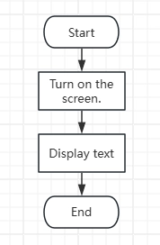
5. Code Logic Flowchart
6. Flashing Steps
Next, we will teach you how to use ESPHome for the first time to write code, including the overall operation process. Please follow us step by step.
Emphasize again here:
The following devices need to be on the same LAN:
① Your computer
② CrowPanel HMI ESP32 Rotary Display
③ Raspberry Pi with the Home Assistant system
Here, our Raspberry Pi with the Home Assistant system acts as the server in this project. Therefore, every time you enter the IP address of this Raspberry Pi with the Home Assistant system, you are entering Home Assistant. Only after entering this page can you proceed with the following operations.
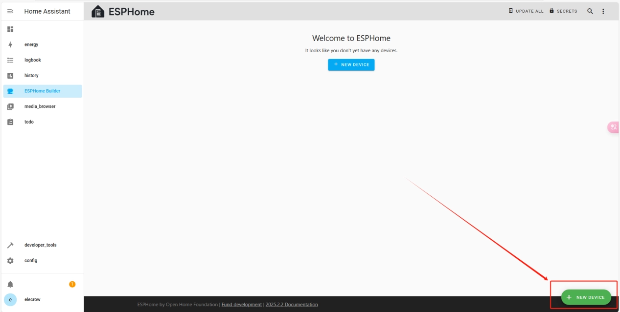
The following operations assume that you have completed the installation steps in the previous lesson and have arrived at the ESPHome main page.
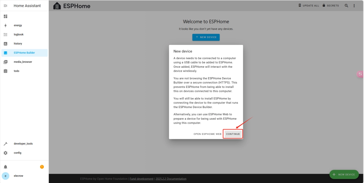
Once the installation is complete, we can start adding devices. Click on + New Device -> Continue.
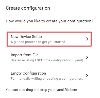
Click “New Device Setup”
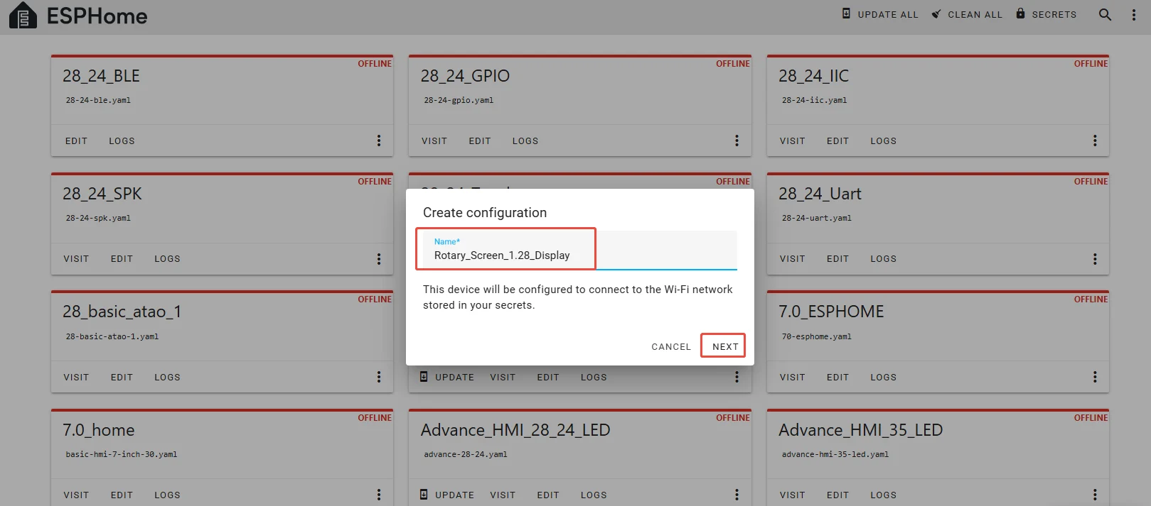
Enter a name and click Next.
(You can use any custom name. Do not include any strange symbols such as @, #, etc.)
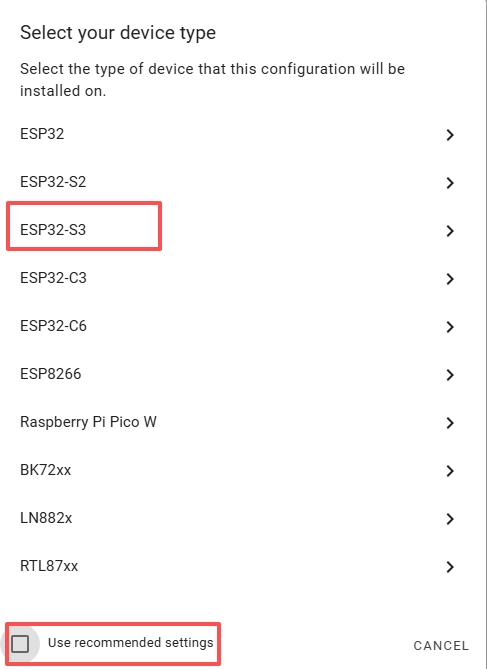
Here, do not check "Use recommended settings."
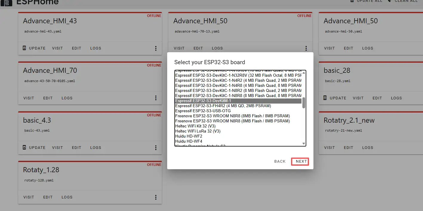
Select the main chip of the CrowPanel 1.28inch-HMI ESP32 Rotary Display, ESP32-S3.
Next, choose any option (since we will replace it in the code later).
Here, click "SKIP".
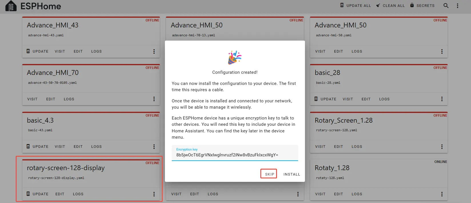
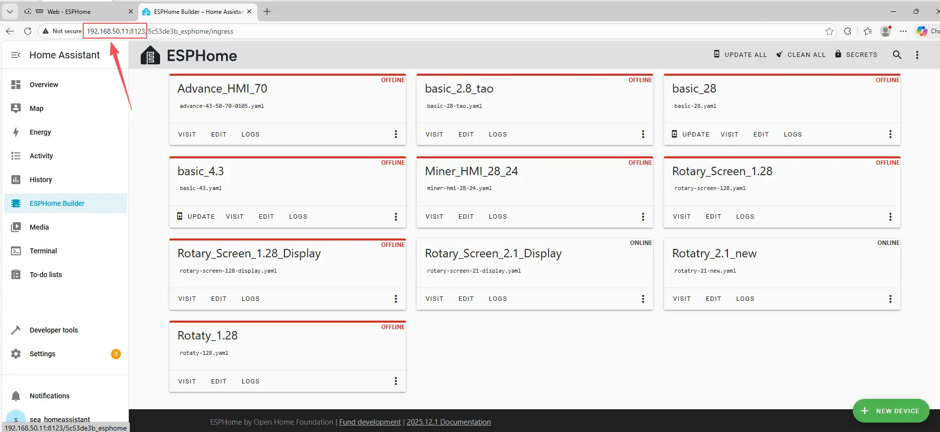
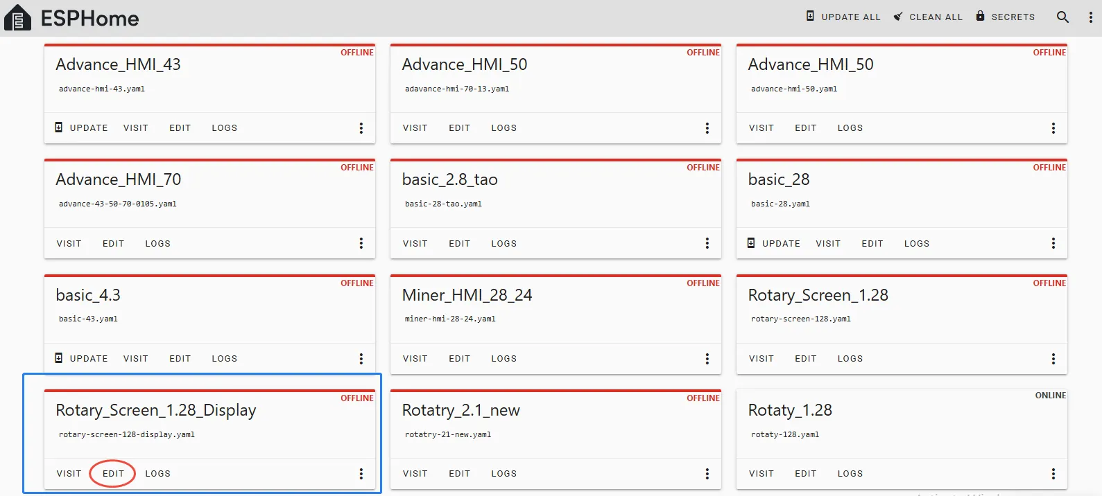
Then, return to the main interface, find the Rotary_Screen_1.28_Display you just created, click "EDIT", and enter the code editor.
This code is automatically generated based on the previous steps. Next, we will make replacements in it to help optimize the code for more efficient operation.
Automatically generated code:

This is the complete code. You can click on the code link below to obtain it.
Next, you can replace the relevant content in esphome and ESP32 as needed. And add the item "PSRAM".
Then, based on your existing code, follow the format shown in the figure to add or replace these codes.
(Other configurations remain unchanged)
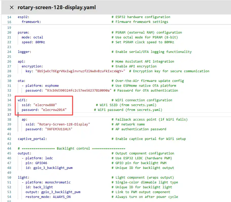
Remember to replace your own Wi-Fi name and password.
Note: This Wi-Fi connection must be in the same local network as your computer and Raspberry Pi!
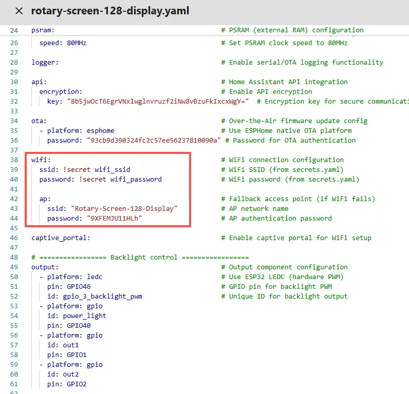
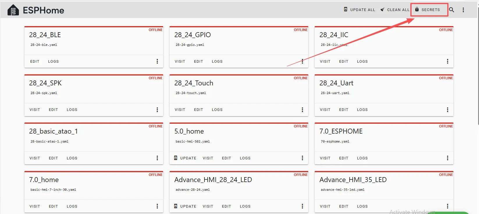
Our Wi-Fi account and password are configured on the ESPHome main page.
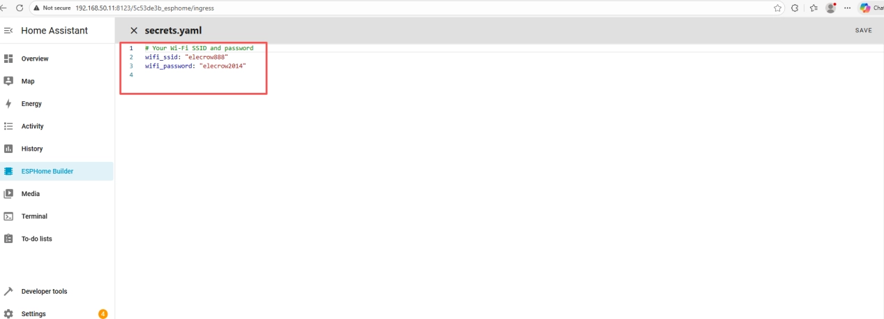
Therefore, we can write it in the code like this, meaning that we are using the Wi-Fi "elecrow888".
Of course, you can also directly write the Wi-Fi account and password in detail in the code.
Note: These items are specific to the device you created and cannot be the same as mine. Just keep the ones you originally created.
You can copy the other functional code from mine.
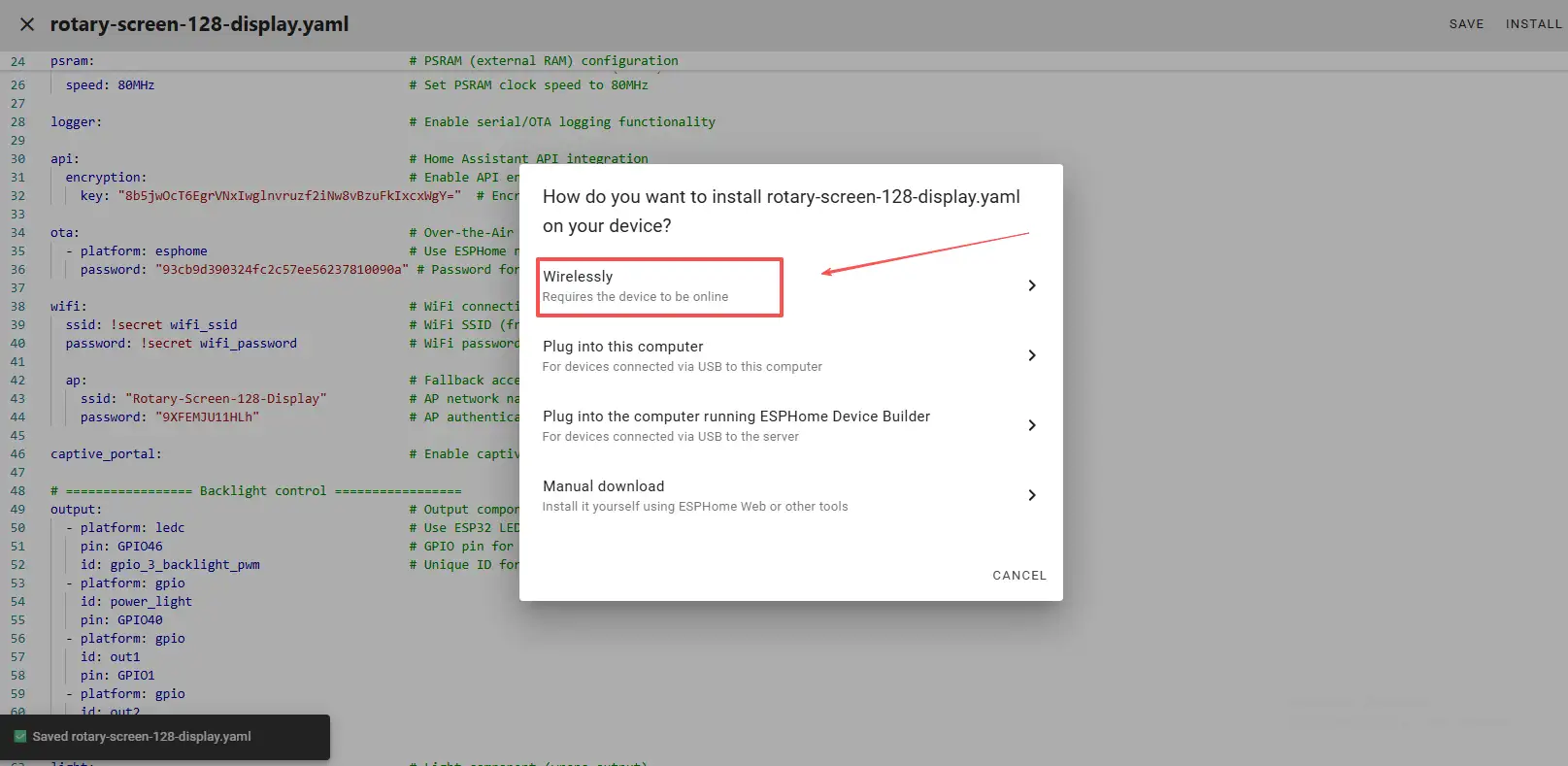
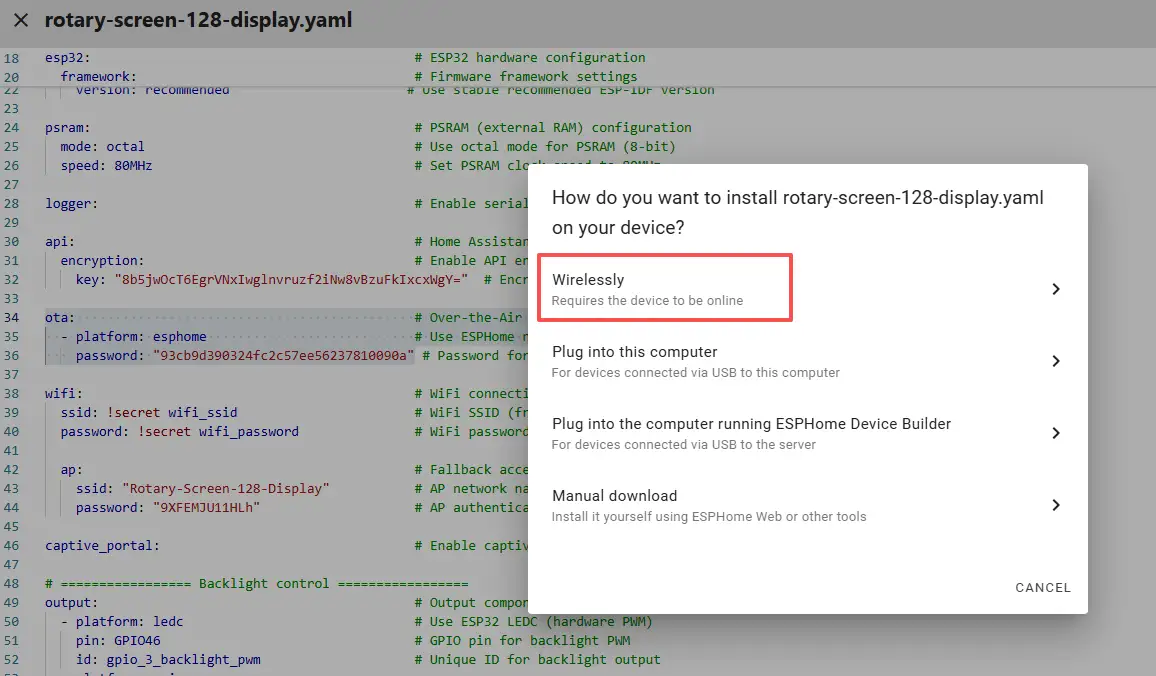
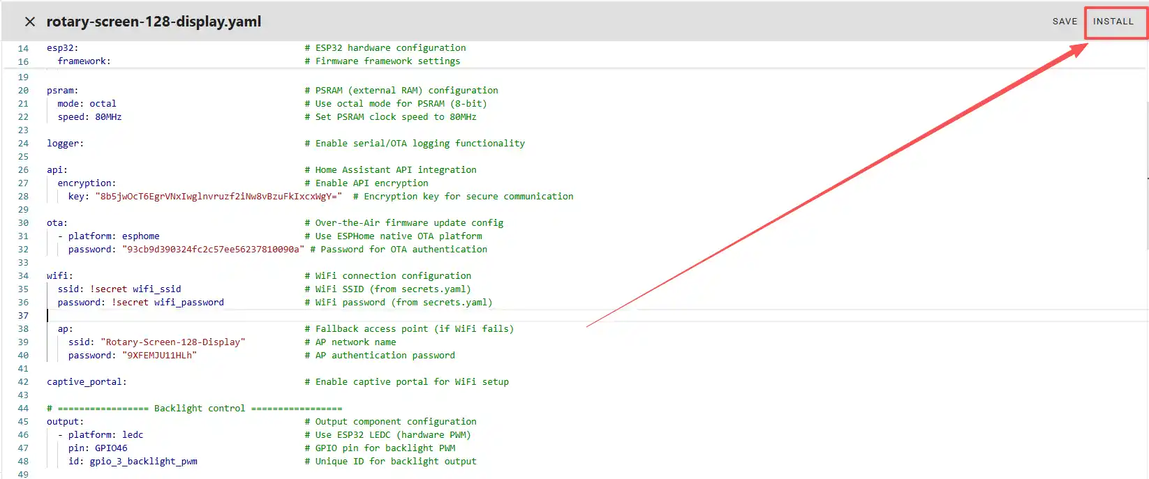
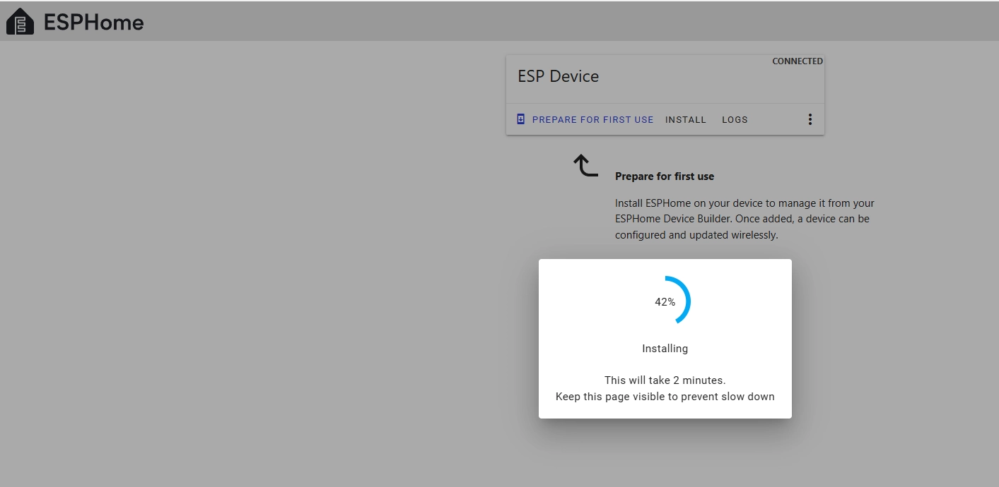
Once the code replacement is complete, click "INSTALL" in the top right corner.
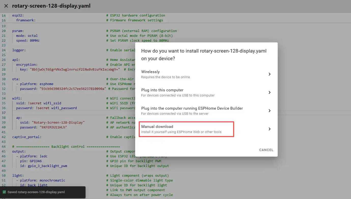
Select "Manual download".
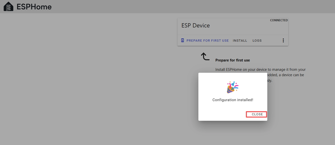
Wait for a few minutes until the installation is complete.
Then, select "Factory format".
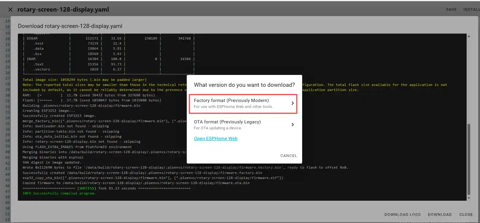
Once the download is complete, you will see the .bin file.
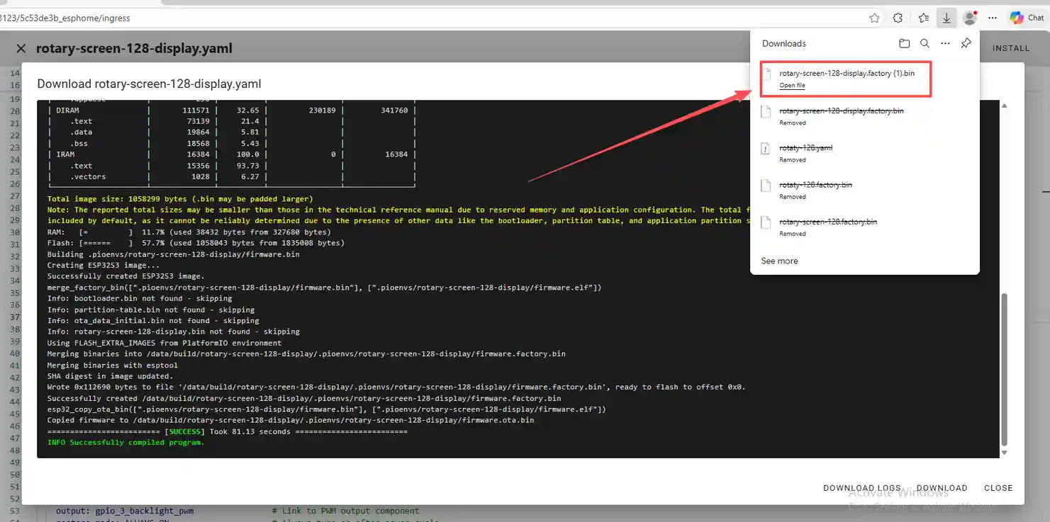
Remember the path of this .bin file.
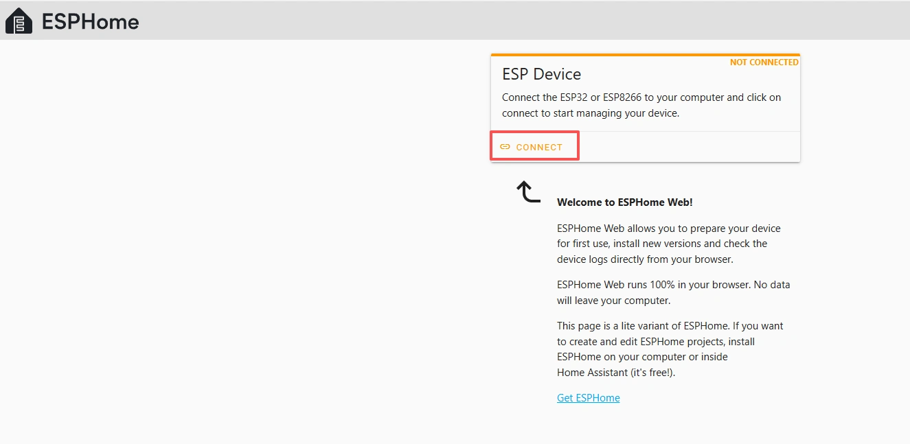
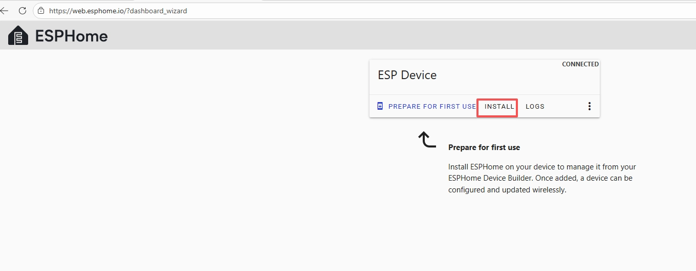
Open the following website: https://web.esphome.io/?dashboard_wizard
After opening this website, you will arrive at this interface:

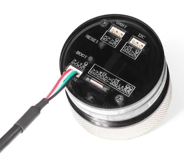
Next, we will flash this .bin file into the CrowPanel 1.28inch-HMI ESP32 Rotary Display.
Connect the CrowPanel 1.28inch-HMI ESP32 Rotary Display to your computer.
Click "Connect"
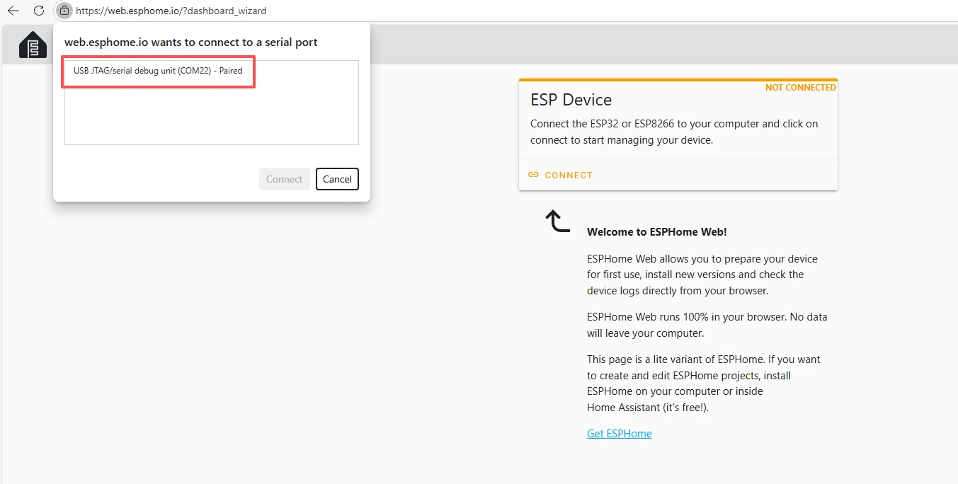
Select the COM port and connect it.
After connecting the CrowPanel 1.28inch-HMI ESP32 Rotary Display, click "Install".
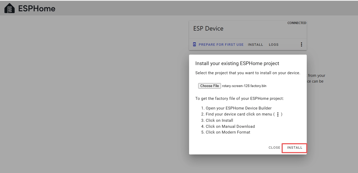
Add the .bin file you just downloaded, then click "Install".
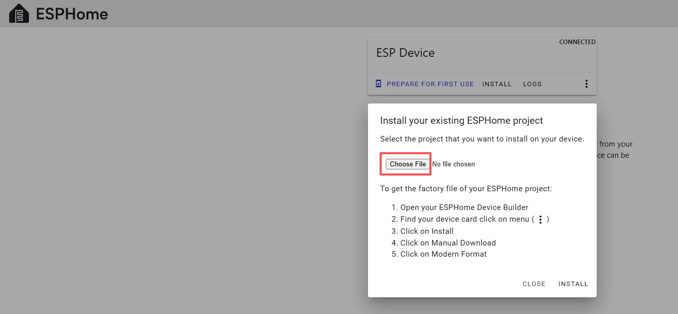
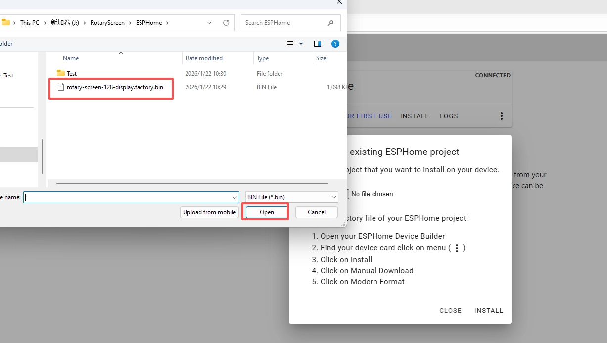
Then select the bin file that you just downloaded.
Click "INSTALL"
Wait for a few minutes.
After the installation is complete, click "Close".
After successfully flashing the .bin file, return to the ESPHome page in Home Assistant.
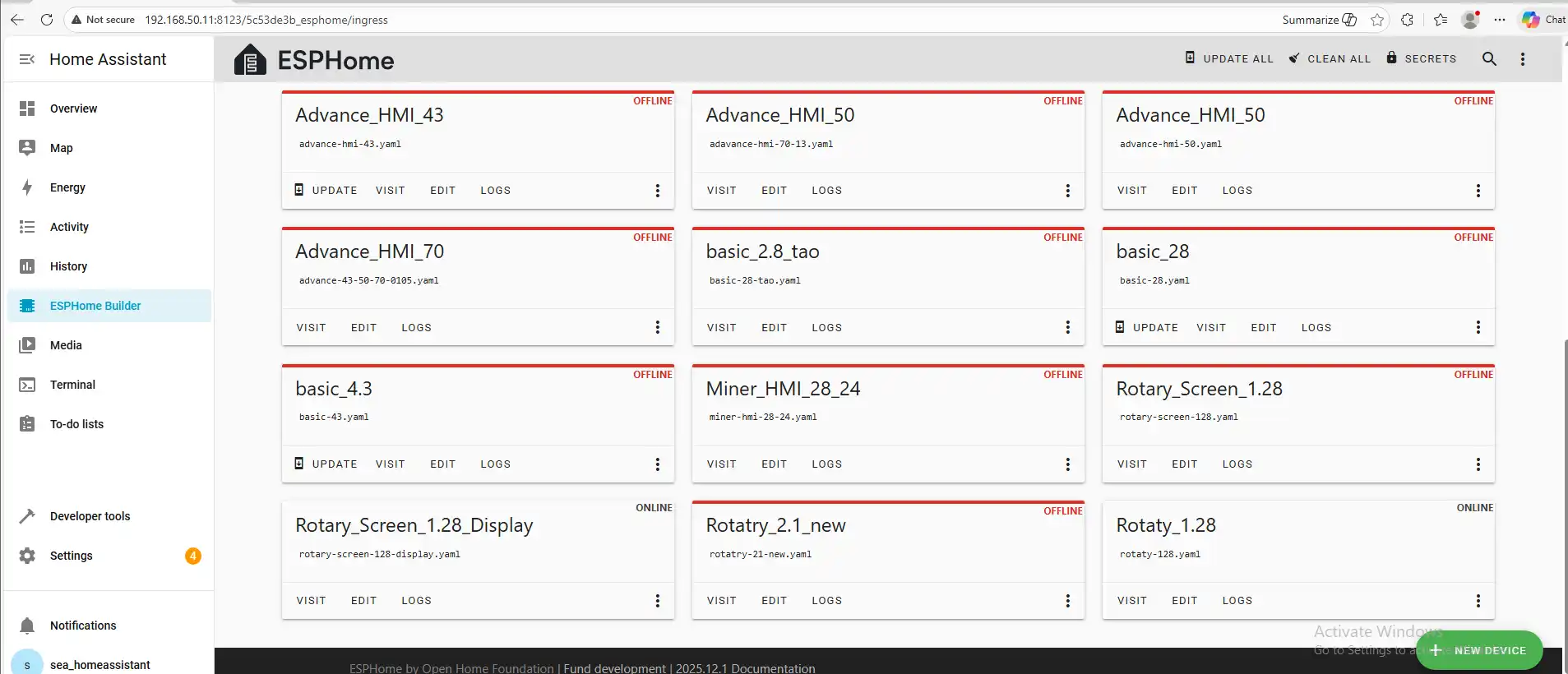
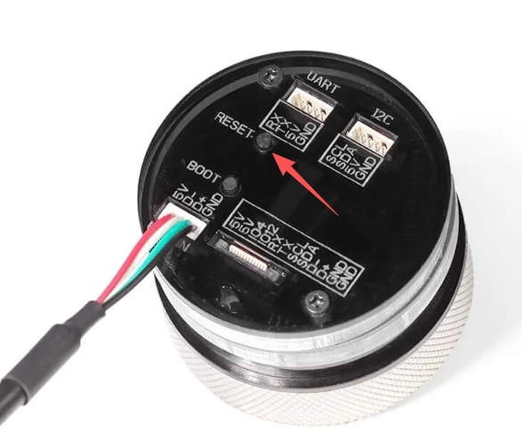
Press the RESET button on the CrowPanel 1.28inch-HMI ESP32 Rotary Display.
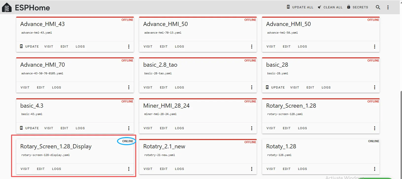
Restart the ESP32 display, and you should see the device you created earlier show as ONLINE in the top right corner.
And if you have also added the functional code we provided, you will be able to see “Hello World!” displayed on the screen.
After it shows ONLINE here, if you make any further modifications to the code and want to upload it again, you can use the Wireless upload method, which will be much more convenient.